BROOKLYN ANIMAL CARE CENTER
832 SHEPHERD AVE, BROOKLYN, NY 11208
RENDERINGS
VIEW FROM SHEPHERD AVENUE
OCTOBER 21, 2019 - PRELIMINARY REVIEW
AUGUST 13, 2018 - PRELIMINARY REVIEW
Eric Adams
Mayor
Thomas Foley, P.E.
Commissioner
January 2022
Design
Consultant
Guide
2

3
LETTER FROM
THE COMMISSIONER
Dear Colleagues,
Welcome to our new and updated Design Consultant Guide. This is an important tool for working with the New
York City Department of Design and Construction to create and renew the public buildings that serve the needs
of all who live, work, and visit here.
Since its creation in 1996, DDC has successfully delivered many of the City’s most important municipal projects
and taken a leading role in guiding New York through times of crisis. With these accomplishments comes an
increased responsibility to deliver quality projects more effectively and efficiently. In 2019, DDC issued its
Strategic Blueprint for Construction Excellence, a detailed plan to streamline the capital construction process
at every level. In addition, the Public Buildings Division issued Public Buildings: Embracing Change, an internal
document which highlighted our design phase process improvements. We’ve sought to improve, streamline, and
better collaborate within the Division and across the agency, and have set high expectations for ourselves and our
design consultants to deliver functional, enduring projects on time and within budget, improving the character of
our communities.
Our policies and practices must also change to ensure that projects are designed and constructed to enhance
public safety in the face of a global pandemic, climate change and other challenges. Through every hurdle, DDC
remains committed to building a sustainable, healthy, and equitable urban environment.
A key part of that vision is also the creation of meaningful business opportunities for Minority- and Women-
Owned Business Enterprises (M/WBEs). Through a focused plan of outreach and support DDC has become a
top-performing agency in the City’s M/WBE program and has successfully lobbied for State legislation that will
further expand prospects for these businesses.
You, our Design Consultants, are crucial partners in this endeavor. Together, we have been charged with
achieving the best value for the public by providing excellence in design and construction, a timely process, and
a cost-effective product. Successful design is fundamentally collaborative. This Guide seeks to make DDC’s
expectations clear by providing an overview of our goals on a phase-by-phase basis and detailing related
deliverables. We hope it will prove to be a valuable resource as we strive to deliver the best possible design and
construction work on our City's public buildings. Let’s get to work…
Sincerely,
To m Fo l e y, P E , C C M , D B I A , N AC
Commissioner
4
Table of Contents
CHAPTER 01: INTRODUCTION
A. THE DEPARTMENT OF DESIGN AND CONSTRUCTION 11
B. THE DIVISION OF PUBLIC BUILDINGS 11
C. PROJECT EXCELLENCE 12
D. THE PROJECT TEAM 13
E. THE DESIGN CONSULTANT GUIDE 14
CHAPTER 02: OVERVIEW OF THE DESIGN PROCESS
A. PROJECT DELIVERY STAGES 17
B. PROJECT PLANNING AND INITIATION 17
C. PROJECT DELIVERY TRACKS 18
D. DESIGN PHASES 20
E. DESIGN PHASE PROCESS AND MILESTONES 22
F. CONSULTANT SERVICES DURING CONSTRUCTION 25
G. CONSULTANT OBLIGATIONS 25
CHAPTER 03: DESIGN & CONSTRUCTION PHASE DELIVERABLES
A. PROJECT DELIVERABLES 29
1) CAPITAL PROJECT DELIVERABLES 29
a. Pre-Schematic Design Deliverables 30
b. Schematic Design Deliverables 30
c. Design Development Deliverables 43
d. 75% Construction Documentation 58
e. 100% Construction Documentation 69
f. Bid Documents 70
g. Bid and Award Deliverables 71
h. Construction Administration Services 72
5
6
2) CAPITAL PROJECT SCOPE DEVELOPMENT (CPSD) DELIVERABLES 75
a. Interim Reports 75
b. Report Preparation 75
c. Final Report 75
d. Master Plan 76
B. GENERAL INFORMATION 77
1) AGENCY CONTACT INFORMATION 77
2) REPORT SUBMISSION FORMAT REQUIREMENTS 78
3) DRAWING SUBMISSION FORMAT REQUIREMENTS 78
4) DRAWING STANDARDS 78
5) MULTIPLE CONTRACTS: DIVISION OF RESPONSIBILITY IN WICKS LAW PROJECTS 79
CHAPTER 04: PROJECT CONTROLS
A. INTRODUCTION 83
B. PROJECT SCHEDULE 83
C. CONSTRUCTION COST ESTIMATING 86
CHAPTER 05: BID PACKAGING REQUIREMENTS
A. INTRODUCTION 95
B. BID PACKAGE COMPONENTS 95
C. ORGANIZING, FORMATTING AND PRESENTING THE BID PACKAGE 96
D. METHODS OF PROCUREMENT 102
E. DDC SPECIFICATION REQUIREMENTS 104
F. CONSULTANT WORK SESSIONS 107
CHAPTER 06: DESIGN CRITERIA
A. GENERAL DESIGN APPROACH 111
B. DEMOLITION 114
C. STRUCTURES AND SOILS 115
D. SITE CIVIL ENGINEERING 118
CHAPTER 07: COMMISSIONING
A. INTRODUCTION 189
B. COMMISSIONING AGENT 189
C. SERVICES 189
D. DELIVERABLES 190
E. COMMISSIONING DESIGN GUIDANCE 192
CHAPTER 08: SUSTAINABILITY AND RESILIENCY
A. SUSTAINABLE DESIGN 203
1) INTRODUCTION 203
2) NYC GREEN BUILDING LAWS 203
3) PERFORMANCE REQUIREMENTS 204
4) DELIVERABLES 209
5) PERFORMANCE REQUIREMENTS PROJECT DELIVERABLES TABLE 214
6) LEED PROJECT DELIVERABLES 216
7) LEED PROJECT DELIVERABLES TABLE 222
B. RESILIENT DESIGN 225
1) INTRODUCTION 225
2) CLIMATE RESILIENCY DESIGN GUIDELINES 225
3) DELIVERABLES 225
CHAPTER 09: PERCENT FOR ART
A. INTRODUCTION 231
B. THE PERCENT FOR ART LAW 231
C. GENERAL INFORMATION FOR THE CONSULTANT 232
D. APPROACHES TO COMMISSIONING PUBLIC ART 233
E. PERCENT FOR ART CONTRACT 233
F. ARTWORK REVIEW INFORMATION 234
G. ARTWORK PAYMENTS 235
H. DELIVERABLES 236
7
8
CHAPTER 10: REGULATORY APPROVALS
A. INTRODUCTION 243
B. REGULATORY APPROVAL SERVICES 243
C. REGULATORY APPROVAL DELIVERABLES 244
D. DEPARTMENT OF BUILDINGS 246
E. NEW YORK CITY COMMUNITY BOARDS 248
F. PUBLIC DESIGN COMMISSION 249
G. LANDMARKS PRESERVATION COMMISSION 256
H. ADDITIONAL REGULATORY AGENCIES 260
1) DEPARTMENT OF CITY PLANNING (DCP) AND THE CITY PLANNING COMMISSION (CPC) 260
2) DEPARTMENT OF TRANSPORTATION (DOT) 260
3) METROPOLITAN TRANSIT AUTHORITY (MTA) 261
4) FIRE DEPARTMENT (FDNY) 261
5) DEPARTMENT OF ENVIRONMENTAL PROTECTION (DEP) 261
6) DEPARTMENT OF PARKS AND RECREATION (DPR) 262
7) DEPARTMENT OF HEALTH AND MENTAL HYGIENE (DOHMH) 262
8) DEPARTMENT OF SANITATION (DSNY) 262
9) ENVIRONMENTAL CONTROL BOARD (ECB) 262
10) UTILITY COMPANIES AND NYS ENERGY RESEARCH AND DEVELOPMENT
AUTHORITY (NYSERDA) 262
11) COMMUNITY BOARDS 263
12) MAYOR’S OFFICE OF ENVIRONMENTAL COORDINATION (MOEC) 263
13) NEW YORK STATE AGENCIES 263
ACKNOWLEDGEMENTS
ACKNOWLEDGEMENTS 266

9
CHAPTER 01
INTRODUCTION
A. THE DEPARTMENT OF DESIGN AND CONSTRUCTION
B. THE DIVISION OF PUBLIC BUILDINGS
C. PROJECT EXCELLENCE
D. THE PROJECT TEAM
E. THE DESIGN CONSULTANT GUIDE
10

A. THE DEPARTMENT OF DESIGN
AND CONSTRUCTION
The New York City Department of Design and Construction (DDC) was established in 1996 to provide project
management services for the City of New York’s capital construction projects. Serving 28 Sponsor Agencies
through its two Divisions, Public Buildings and Infrastructure, DDC builds and renovates public buildings,
streetscapes, plazas, and subgrade infrastructure.
B. THE DIVISION OF PUBLIC
BUILDINGS
Design opportunities throughout DDC’s Division of Public Buildings range from major new public buildings
to retrofits and upgrades of existing buildings. Regardless of scale or scope, every project represents an
opportunity to enhance the public realm and achieve the highest quality of design and construction for the City’s
public buildings and spaces. The design process is a collaborative effort between the Consultants, the DDC
Project Team, the Sponsor Agencies, and Regulatory Agencies, to fully explore programmatic requirements,
site conditions, context, budget, and other factors leading to the development of a creative, responsible, and
functional design in full compliance with all applicable codes, local state and federal laws, specifications,
standards, and project objectives.
As well, our public projects must respond and adapt to the recent global pandemic to ensure public health while
ensuring public value. Along with our City agency and industry partners, we have begun to develop best practices
and procedural modifications that promote the health, safety and welfare for the public in order to mitigate the
risk of viral transmission within a facility and/or active construction site.
DDC projects include cultural institutions, libraries, government offices, laboratories, sanitation facilities,
emergency shelters, transportation facilities, firehouses, health clinics, senior centers, child care centers, courts,
correctional facilities, police precincts, and emergency medical stations. Sponsor Agencies currently include:
Department of Cultural Affairs (DCLA), Department of Parks and Recreation (NYC Parks), Brooklyn Public
Library (BPL), New York Public Library (NYPL), Queens Library (QL), Department of Environmental Protection
(DEP), Department of Health and Mental Hygiene (DOHMH), Office of the Chief Medical Examiner (OCME),
Department for the Aging (DFTA), Department of Youth and Community Development (DYCD), Administration
for Children’s Services (ACS), Agency for Childhood Development (ACD), Department of Citywide Administrative
Services (DCAS), Department of Homeless Services (DHS), Department of Consumer Affairs (DCA), Human
Resources Administration (HRA), Office of Court Administration (OCA), Department of Transportation
(DOT), Taxi and Limousine Commission (TLC), Department of Sanitation (DSNY), Department of Correction
(DOC), Fire Department (FDNY), Police Department (NYPD), Department of Information Technology and
Telecommunications (DOITT), Department of Education (DOE), Department of Probation (DOP), the Mayor’s
Office of Criminal Justice (MOCJ), and NYC Emergency Management (NYCEM).
The specific project goals of each Sponsor Agency are served by individual DDC Program Units. The Program
Units make up the principal organizational framework of the Public Buildings Division, and are supported
by technical, design, budget, and contract processing resources within DDC. The Program Units are directly
responsible for managing projects from the initial program requests by the Sponsor Agency through design,
construction completion, and acceptance for occupancy. Each Program Unit is headed by a Program Director
whose primary responsibilities are to guide and oversee the implementation of a Sponsor Agency’s capital
construction program.
11
CHAPTE R 01: I NTROD UCTION
A. THE DEPARTMENT OF DESIGN AND CONSTRUCTION
B. THE DIVISION OF PUBLIC BUILDINGS
01
CHAPTE R 01: I NTROD UCTION
C. PROJECT EXCELLENCE
C. PROJECT EXCELLENCE
The City of New York is committed to achieving excellence in design and construction across its portfolio of
public works by delivering quality infrastructure and public buildings that contribute to a thriving, equitable,
sustainable and resilient city for all New Yorkers. As part of this commitment, the Department of Design
and Construction’s Project Excellence program builds on a strong tradition of innovation in architecture and
engineering through strategies and practices that balance aesthetics, functionality, cost, constructability, and
durability to bring form and meaning to public space.
Project Excellence encompasses all aspects of project delivery, from capital project planning through design,
construction, commissioning, and close-out, to ensure on time and on budget delivery of exemplary civic projects.
Integrated project delivery practices include enhanced project initiation and management tools, Quality-Based
Selection (QBS) and best value procurements, performance evaluation and management, knowledge sharing,
and continuing education. Together, these strategies ensure that all capital projects delivered to the City are
inspiring, enduring, practical, constructible, and economical.
Achieving Project Excellence requires all team members to engage collaboratively in the capital project delivery
process, prioritizing strategies that make responsible use of public funds and offer the best value for the
City. DDC’s project managers, technical reviewers, and support staff work to guide projects through complex
and demanding project delivery processes in partnership with the most creative and experienced design and
construction professionals. DDC and our partners share a commitment to Project Excellence in the public realm
as characterized by the following overarching concepts:
Project Excellence utilizes the power of design and construction to positively transform our
public space, inspiring pride in the people and City of New York. The design of public buildings and
infrastructure must be guided by a civic consciousness and social responsibility to provide spaces that
promote discourse, exemplify accessible government, and inspire pride in our communities. The design
and construction process must reflect a collaborative effort that is inclusive of all stakeholders, including
sponsor, partner, and regulatory agencies, and the community.
Project Excellence shapes the city we envision for today and the future by creating enduring and
inclusive public spaces. With design and construction of public projects comes the responsibility of
shaping the City for generations to come. Dignified, universally accessible, and community-oriented, public
spaces must make all New Yorkers feel welcome and valued, comfortable and secure. By thoughtfully
responding to surrounding context, including neighborhood character and natural systems, the design
must create and reinforce a sense of place that is enhanced by strong connections to existing community
resources and mobility networks. The design and construction process must engage relevant stakeholders
and experts to consider cultural context and integrate artwork wherever possible in support of meaningful
public spaces.
Project Excellence protects the legacy of our public space by carefully considering practical
solutions that address the needs of our City. Public projects must be well suited for their intended
use and adaptable to future needs. Our public buildings and infrastructure must meet the needs and
aspirations of New York City’s public agencies as expressed in their individual missions, goals, standards,
and requirements. The design must seek a creative balance between functional and programmatic
requirements, operational and maintenance protocols, construction practices, and performance and
innovation. Sustainable, resilient, durable, and easily maintained, the project must be guided by a holistic
view of the capital asset over its expected lifespan. The design must consider solutions to long-term and
emergent risks and opportunities, such as changing climate and public health and safety conditions, as
well as new technologies and ways of living, working, and connecting.
12

CHAPTE R 01: I NTROD UCTION
D. THE PROJECT TEAM
Project Excellence strengthens the character of our public space by delivering constructible
capital projects with safety and integrity. Building New York City requires the ability to execute projects
in a safe, effective, and timely manner while maintaining the integrity of the design throughout construction.
The design of our public buildings and infrastructure must be represented by complete, comprehensive,
and accurate contract documents that are clearly detailed and coordinated across disciplines, and that
meet or exceed requirements of code, zoning, accessibility, and local laws. Specifications must be carefully
coordinated with drawings and material schedules and be tailored to the requirements of each project.
Materials and systems must be proven, readily available, and achievable with local construction practices to
minimize lead times, eliminate cost overruns, and prevent construction delays.
Project Excellence supports the value of our public space by employing an economical approach
that leverages City resources to build lasting community assets. Design and construction by and for
the City requires conscientious attention to schedule, budget, and operational costs to ensure that public
funds are well spent, and communities well served. The project must incorporate a life-cycle cost analysis
approach and prioritize selection of long-lasting systems and assemblies that are achievable within the
allocated budget. Systems must perform to the highest standards of human health, comfort and efficiency,
meet or exceed energy requirements, and operate as designed. The project must be calibrated to reduce
construction and operating costs and complexity, positively impact the health of people and the environment,
and use natural resources wisely. Using City-wide and agency standards and best practices, innovative
methodologies, and appropriate technologies, the design must add value and do more with less.
To support Project Excellence, DDC seeks architects, landscape architects, planners, designers, engineers,
construction managers, contractors, and design-build teams who are dedicated, responsive, and collaborative, and
who possess the management skills necessary to complete work on time and on budget. DDC’s partners must
have a proven track record of delivering quality projects while resolving complex requirements and navigating
unforeseen circumstances. Team-oriented and adept at balancing competing demands, these professionals must
go beyond the creation of contract documents to serve as facilitator, mediator, and interpreter, building trust
among the many stakeholders throughout the life of a project.
D. THE PROJECT TEAM
The Project Team includes:
1. THE CONSULTANT TEAM, INCLUDING ALL REQUIRED SUB-CONSULTANTS.
2. REPRESENTATIVES OF THE SPONSOR AGENCY.
3. THE DDC PROJECT TEAM:
a. The DDC Project Manager, who will act as the main point of contact for the Project Team. The DDC
PM will also coordinate communications with the internal DDC Units that support the Consultant and
the project including the DDC Project Controls Unit, Office of Environmental and HazMat Services
(OEHS), Office of Geotechnical Investigations (OGI), and M/WBE Compliance Unit.
b. The Design Liaison, who ensures that the project meets the civic design requirements of Project
Excellence and shepherds projects through the Public Design Commission review and approval
process.
c. The DDC Architecture and Engineering (A&E) Review Team, led by a Team Leader of the appropriate
discipline and including Team Members representing each trade as applicable, including Architecture;
Structural, Mechanical, Electrical, Plumbing and Civil Engineering; Accessibility; Landscape
Architecture; Historic Preservation; Public Art; Sustainable Design; and Commissioning.
13
01
CHAPTE R 01: I NTROD UCTION
E. THE DESIGN CONSULTANT GUIDE
4. A COMMISSIONING AGENT CONSULTANT, WHEN REQUIRED, UNDER DIRECT
CONTRACT TO DDC.
5. A CONSTRUCTION MANAGER, WHEN REQUIRED, UNDER DIRECT CONTRACT
TO DDC.
E. THE DESIGN CONSULTANT GUIDE
DDC undertakes a wide variety of projects in support of its Sponsor Agencies, making each project unique
and standardization of project delivery methods a challenge. This Design Consultant Guide outlines qualitative
expectations and describes broad requirements that pertain to all projects.
Descriptions of goals and deliverables are intended to help the Consultant, DDC, and Sponsor Agencies
understand expectations and evaluate the acceptability of completed tasks. A detailed chapter on Design
Criteria is provided to describe the basis of DDC’s evaluation of the Consultant’s work product.
Many of DDC’s design projects are initiated through Requirement Contracts for design services. The
Requirements Contract is necessarily generic regarding specific project scopes since the projects to be
undertaken are not known at the time of contract initiation. The Task Order will state all the parameters of
the specific project and incorporates the Project Objectives (PO) which includes the Scope of Work. All
tasks shall be carried out as directed in this Design Consultant Guide unless the Task Order or other written
documentation from DDC explicitly states otherwise.
The Guide describes the design criteria of the Agency, the goals, services, and deliverables expected, and
necessary approvals and procedures.
In addition to this Guide, Consultants should familiarize themselves with Sponsor Agency design guides,
requirements, manuals, specifications, or standards. These should be reviewed to ascertain any potential
conflicting goals or objectives. The resolution of conflicts is the responsibility of all parties involved.
14

15
CHAPTER 02
OVERVIEW OF THE
DESIGN PROCESS
A. PROJECT DELIVERY STAGES
B. PROJECT PLANNING AND INITIATION
C. PROJECT DELIVERY TRACKS
D. DESIGN PHASES
E. DESIGN PHASE PROCESS AND MILESTONES
F. CONSULTANT SERVICES DURING PROCUREMENT
AND CONSTRUCTION
G. PROFESSIONAL RESPONSIBILITY
16

CHAPTE R 02: OVE RVI EW OF TH E D ES IG N PROCE SS
A. PROJECT DELIVERY STAGES
B. PROJECT PLANNING AND INITIATION
A. PROJECT DELIVERY STAGES
There are four stages in the delivery of capital projects from initiation to the completion of construction:
1) PROJECT PLANNING AND INITIATION
During the Project Planning and Initiation stage, DDC evaluates the capital project scope and budget
to ensure the project has adequate funding. DDC develops a baseline schedule template, prepares the
specific project's requirements, selects the Consultant, acquires funding from the Office of Management and
Budget (OMB), registers the task order with the Comptroller, and issues the Notice to Proceed (NTP) to the
consultant.
2) DESIGN
a. Documentation
This stage typically includes the Schematic Design phase; Design Development phase, and
Construction Documents phase. Design may at times also include a Pre-Schematic phase prior to
Schematic Design or at times consist only of a CPSD (Capital Project Scope Development) study. For
more information, see Chapter 03: Design and Construction Phase Deliverables.
b. Bid / Award
This phase includes the bid period, selection of the Contractor/s and the registration of construction
contract/s. For more information, see Chapter 03: Design and Construction Phase Deliverables.
3) CONSTRUCTION
Construction contracts are awarded either through a competitive bid process, in which the lowest responsible
and responsive bidder is selected or through pre-awarded requirements contracts managed by DDC’s Job
Order Contracting Service (JOCS).
B. PROJECT PLANNING AND INITIATION
The Project Planning and Initiation stage begins when the Sponsor Agency submits a Project Initiation (PI) request,
which includes a general description of the project, a summary of the required work, and information on funding.
DDC’s Front End Planning (FEP) Unit reviews and evaluates the scope and budget to ensure the project is viable.
In order to verify that scope and budget are aligned, DDC’s FEP, along with technical support from A&E, conducts
a preliminary project investigation to review site constraints, identify requirements for compliance with codes, local
state and federal laws, and other City obligations, explore construction logistics and so forth, to demonstrate a
design approach that is achievable within the budget. FEP’s findings are compiled into a report along with a baseline
schedule and the Project Objectives. This report details the scope of work and identifies the track for design delivery
(see Section C in this chapter). Upon initiation of the project, the complete Front End Planning Report will be issued
to the Consultant assigned to the project. When a test fit is included in the Front End Planning Report, it indicates
one possible solution that was developed to determine project viability. It does not represent a preferred scheme, nor
is it required to be among the options proposed by the Consultant during Schematic Design.
17
02

CHAPTE R 02: OVE RVI EW OF TH E D ES IG N PROCE SS
C. PROJECT DELIVERY TRACKS
The Project Planning and Initiation stage includes the identification of the key members of the DDC Project Team,
including the Front End Planning Program Executive, the Project Manager, the A&E Team Leader, and the Design
Liaison. The DDC team discusses the project in detail while taking into consideration various regulatory pathways
as well as design services procurement options based upon project scope, schedule and budget. All decisions
made during this stage are vetted by DDC’s Strategy Board.
Once Strategy Board recommends the project for initiation, the Design Liaison coordinates with DDC’s Agency
Chief Contracting Officer (ACCO) to procure design services. For all projects, large and small, Consultants are
invited to attend a site visit to become familiar with the site and scope of work. The design procurement process
requires Consultants to identify how they will meet M/WBE participation goals established for the project.
Simultaneously, the Project Manager prepares a Certificate to Proceed (CP) request for submission to OMB to
obtain funding approval for the project and subsequently prepares the Agreement, which includes the FEP Report
and Project Objectives, for submission to the Comptroller to register the contract. Upon approval of the CP,
selection of a Consultant, and registration of the Task Order, a Notice to Proceed (NTP) is issued to the consultant
and a design kick-off meeting is scheduled by the Project Manager.
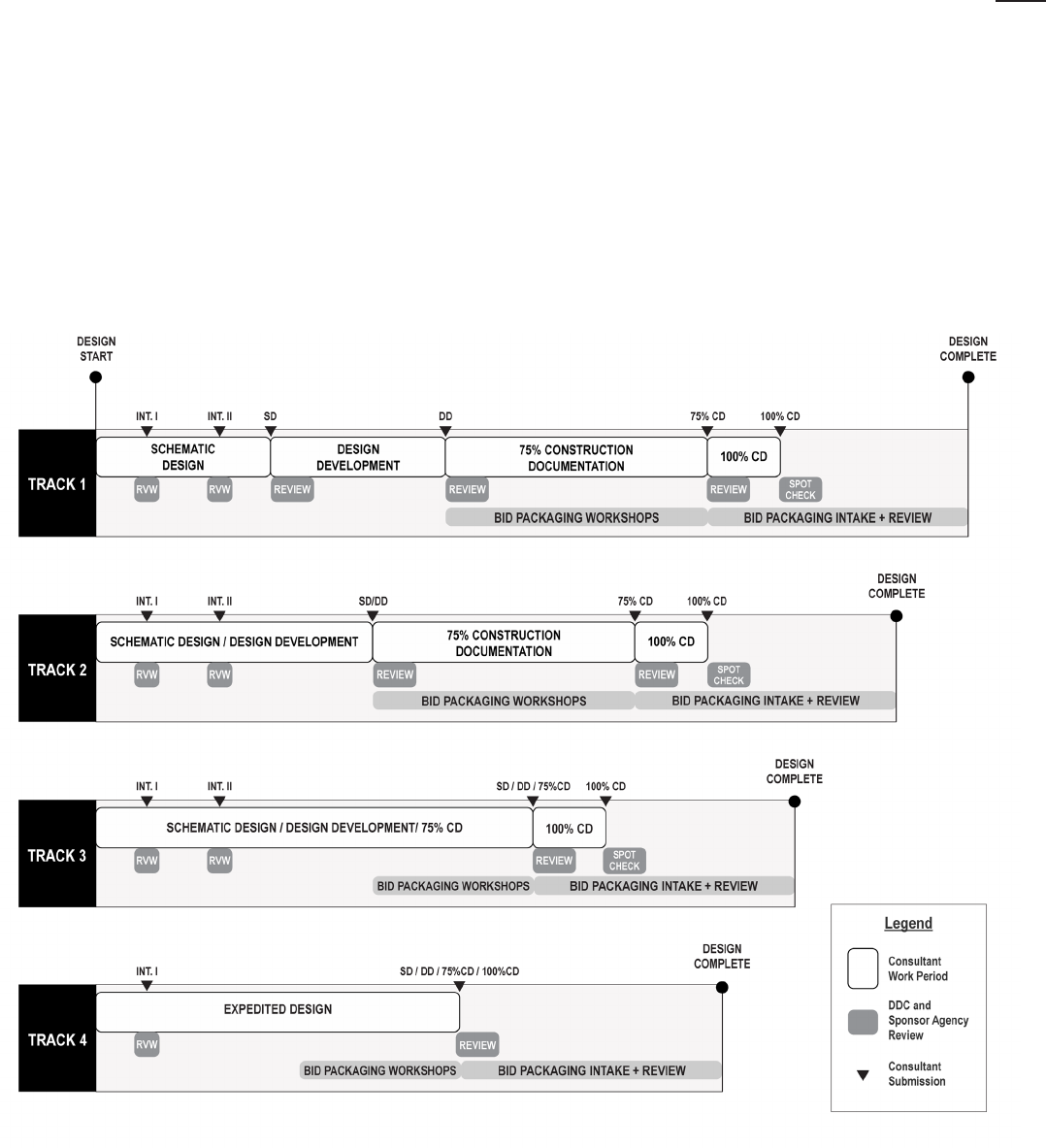
C. PROJECT DELIVERY TRACKS
1) PROJECT TRACKS AND TYPES
Projects follow one of four project delivery tracks according to the type of work and level of complexity. The
project track will be identified in the FEP Report and Project Objectives (PO).
a. Track 1 includes new construction, major renovations, and additions. Track 1 encompasses
all phases, which include Pre-Schematic Phase (optional), Schematic Design, Design
Development, 75% Construction Documents phase, and 100% Construction Documents
phase.
b. Track 2 includes complex building system upgrades involving more than one system, such as
building envelope or HVAC system reconstruction/rehabilitation. It has a combined Schematic
Design and Design Development Phase, 75% Construction Documents Phase, and 100%
Construction Documents phase.
c. Track 3 includes simple building system upgrade projects. It includes Schematic Design,
Design Development and 75% Construction Documents combined into a single phase,
followed by 100% Construction Documents Phase.
d. Track 4 is for projects with very limited scope. In this very expedited track, Schematic
Design, Design Development, 75% and 100% Construction Documents are combined into a
single phase
e. Capital Project Scope Development (CPSD) studies are sometimes required to
enable the City to identify advanced portfolio planning, project scope and cost prior to capital
commitment. CPSD services may be requested for any type of City project including but not
limited to buildings, structures and facilities, site work, etc. A CPSD study may also include
large-scale portfolio planning, master planning, space programming, design standards and
technical research. Since the extent of each CPSD will vary, design services will be specific
to the nature of the project and may include such items as the investigation of existing
conditions, analysis of regulatory pathways, analysis of zoning and code, analysis of the
18
CHAPTE R 02: OVE RVI EW OF TH E D ES IG N PROCE SS
C. PROJECT DELIVERY TRACKS
Sponsor Agency’s operational requirements and programming, as well as the study of design
alternatives to promote efficiency and control costs. This study concludes with a report by
the Consultant and a review by DDC. No construction phase services are included in this
type of project.
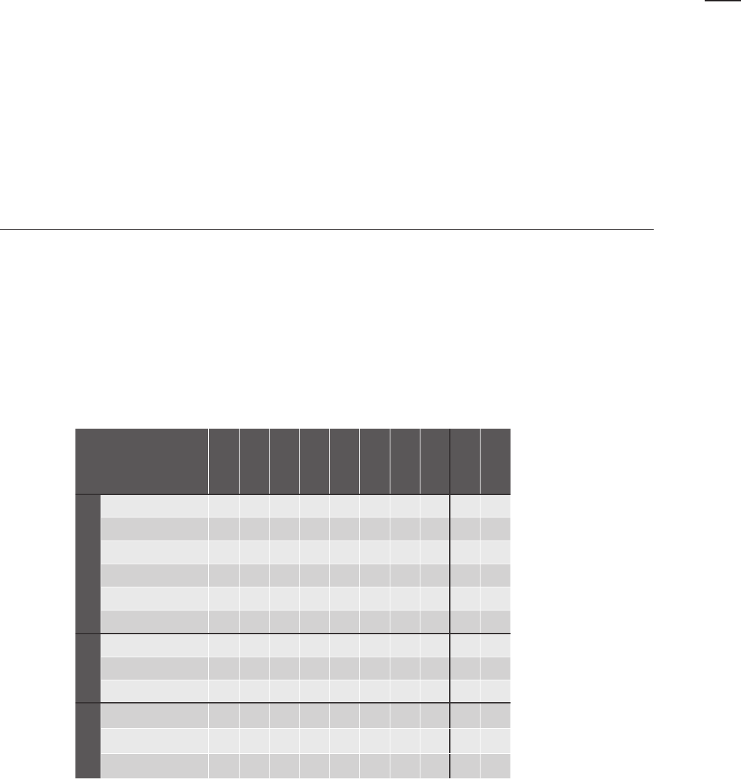
2) REQUIRED PHASES BY PROJECT TRACK
The chart below is a general illustration of requirements for various project types in the Division of Public
Buildings. A Front End Planning (FEP) Report and Project Objectives (PO) are provided for each project.
These describe project-specific requirements and obligations of the design professionals, and identify
which phases and submissions will be required, including any noted as optional.
19
02

CHAPTE R 02: OVE RVI EW OF TH E D ES IG N PROCE SS
D. DESIGN PHASES
D. DESIGN PHASES
The Design Phases can be configured differently depending on the scope of the project. If the project requires
preliminary services, such as site selection or program definition, the Front End Planning Report and Project
Objectives (PO) will call for a Pre-Schematic phase. Otherwise, a typical project will consist of three phases that
build upon each other: Schematic Design, Design Development, and Construction Documents. Deliverables for
each phase can be found in Chapter 03: Design and Construction Phase Deliverables. All submissions shall be
made in accordance with the project schedule; see Chapter 04 for details. The goals of the Design Phases for
most projects are as follows:
1) PRE-SCHEMATIC DESIGN
A Pre-Schematic phase may be required prior to Schematic Design when an investigation is necessary to
clarify the programming requirements, or other specific uncertainties must be resolved before Schematic
Design can begin. The goal of Pre-Schematic Design is to establish a defined scope of work acceptable to
all stakeholders to transition into Schematic Design without ambiguity related to the basis of design. The
Pre-Schematic scope may include programming, or limited investigations relative to site analysis/selection
and shall be accompanied by associated cost estimates. The phase concludes with a report for review.
For information on requirements of the DDC Design Reviews, see the information in section E.5 of this
Chapter.
2) SCHEMATIC DESIGN
The goal of schematic design is to establish an integrated design direction that synthesizes approaches
towards zoning, life safety, accessibility, building systems, sustainability, resiliency, energy code compliance,
site/community context and civic design criteria.
Prior to developing design options, it is critical to demonstrate a thorough understanding of the project
site and surrounding context, and to identify questions to explore in the options phase. This analysis
must examine the project site’s existing conditions, the proposed facility program, the Sponsor agency's
operational requirements, code and zoning requirements, and any other issues that may influence the
design, cost, schedule, and overall delivery of the project.
Studying design options allows the Project Team to explore and compare various approaches to the project
design, testing each to weigh benefits, expose flaws, and challenge assumptions. Even when the range
of viable approaches is narrow, this process is critical. Ultimately, the consultant is expected to deliver a
design that meets the city's budget, needs and satisfies the project’s objectives; the study of alternative
approaches, conducted collaboratively with the entire Project Team, ensures that the most appropriate
solutions are adopted.
This work is intended to encourage creative problem-solving in order to find consensus amongst the entire
project team on major issues affecting the project. At the conclusion of studying options, a single design
scheme must be documented that reflects this consensus and includes approaches to the topics explored
such as satisfying regulatory requirements, integration of scope and program, the project’s exteriors and
site design, and engineering systems and services.
The Schematic Design phase normally includes two interim submissions for DDC review. The review of the
Schematic Design Interim Submissions occurs without stoppage of the Consultant’s work.
As is the case with all Consultant deliverables, the Project Team will review the submission and generate
written comments, which must be addressed and resolved by the Consultant in the advancement of the
project. For information on requirements of the DDC Design Reviews, see the information in section E.5 of
20

CHAPTE R 02: OVE RVI EW OF TH E D ES IG N PROCE SS
D. DESIGN PHASES
this Chapter. The Schematic Design phase concludes with a submission consisting of a Schematic Design
Final Report, including engineering narratives and a cost estimate.
Approval by the Public Design Commission (PDC) and/or Landmarks Preservation Commission (LPC),
depending on which is applicable, may be required at this phase. For more information, see Chapter 10,
Regulatory Approvals.
3) DESIGN DEVELOPMENT
The process of advancing a scheme to Design Development must validate, develop, and refine the project,
including all design elements, building systems, materials, details, equipment, maintenance and operational
requirements, and life-cycle costs, demonstrating that all decisions are justifiable on the basis of value.
These elements must be fully coordinated across all disciplines. Any open issues regarding zoning, code
compliance, and neighboring property access should be resolved and if determinations from DOB are
required for the proposed design, the Consultant must obtain written responses prior to submittal of the
final DD package.
The Consultant shall notify DDC if they believe that the project scope cannot be achieved within the
approved budget, but this does not relieve the Consultant of their responsibility to deliver a project that
adheres to the budget. At the end of the Design Development Phase, all major design decisions are made
final.
This phase concludes with a submission consisting of a Design Development Report (including updates
and development to the contents of the Final Schematic Design Report), architectural and engineering
drawings, outline specifications, and a cost estimate. For information on DDC reviews, see the information
in section E5 of this Chapter.
4) CONSTRUCTION DOCUMENTS
During this phase, the Consultant prepares final Construction Documents, including drawings and
specifications, for regulatory approval and public bidding or award to a pre-qualified contractor under
DDC’s Job Order Contracting Services (JOCs). Detailed design intent for all construction elements
and assemblies must be fully integrated with the entire project scope and must reflect full regulatory
compliance
There are two submissions during this phase: one at 75% CD and one at 100% CD. In addition to the
drawings, a cost estimate, engineering calculations and specifications are required for review by DDC at
the 75% and 100% submissions.
Final submissions to PDC and LPC must be made during this phase. Submission to the DOB is required
prior to the 75% CD submission. Any objections from the Plan Examiner should be resolved prior to the
100% Submission, or a copy of the outstanding objections must be submitted to DDC with this package.
DDC construction contracts are awarded through a sealed competitive bid process, in compliance with
State and local laws, through which the project is awarded to the lowest responsive and responsible bidder.
It is not permissible for the Consultant to collaborate with the contractors to develop design intent prior to
the bid. Therefore, the Consultant is advised that the success of the bid and award process, as well as the
construction process itself, can be greatly enhanced through their efforts to produce bid documents that
are clear, complete, and thoroughly coordinated.
Delegated Design is not permitted except as expressly authorized by the Commissioner in writing.
21
02

CHAPTE R 02: OVE RVI EW OF TH E D ES IG N PROCE SS
E. DESIGN PHASE PROCESS AND MILESTONES
E. DESIGN PHASE PROCESS
AND MILESTONES
Every Design Phase shares the following basic organizational structure:
1) KICK-OFF MEETING
Every project begins with an official Kick-Off Meeting. The Kick-Off Meeting is attended by the Consultant,
sub-consultants, Sponsor Agency representatives, the DDC Project Team (see Chapter 01, paragraph D)
and additional DDC team members as may be required. At this meeting important project requirements
shall be discussed, including but not limited to:
a. Requirements of the Agreement.
b. Identification of responsibilities, expectations, contact information, and establishment of
protocols for all stakeholders.
c. Project Intent, including, but not limited to:
i. Project Scope and Goals (as defined in the Front End Planning Report and Project
Objectives)
ii. Commissioning. See Chapter 07: Commissioning.
iii. Sustainable Design and Resiliency goals. See Chapter 08: Sustainability and Resiliency.
iv. Percent for Art, if applicable. See Chapter 09: Percent for Art.
d. Design Phase milestones and expectations for submissions of deliverables, including the
BIM Execution Plan if applicable.
i. Review Protocols
ii. Design Compliance Forms
e. Sponsor Agency standards, if applicable
f. Budget
g. Site Data, including information about site surveys and borings
h. Hazardous Material Testing
i. Schedule
See Chapter 04: Project Controls
j. Thereafter, all the following phases will commence with a kick-off meeting that will lay out
the expectations for that phase.
2) PROGRESS MEETINGS
Bi-weekly progress meetings, held at DDC, shall be conducted throughout all phases. These meetings
are expected to be constructive exchanges of information and ideas to advance the project. The DDC
Project Manager schedules progress meetings and workshops. Meetings and workshops shall be indicated
on the Consultant’s schedule and may include issues such as programming, landscape, site conditions,
22

engineering systems, historic preservation, sustainability, active design, accessibility, cost estimating, design
value, technical specialties, specifications, and permits and approvals. Additional meetings may be required
with the Community Board or group, LPC, PDC, and the Sponsor Agency.
a. The Consultant must prepare a detailed agenda for each Progress Meeting. The agenda
must identify issues to be discussed by discipline and assign a time slot to each issue in
order that the required subject matter experts may utilize their time efficiently. The meeting
agenda must be shared with DDC at least 3 days ahead of the meeting.
b. The Consultant must prepare draft minutes for distribution to the attendees within three
days of the meeting or workshop. Once comments have been received from attendees, the
Consultant must issue the final minutes to the Project Manager. When recording minutes,
the Consultant shall number each meeting consecutively and record the date, place, and
attendees. The minutes shall include the agenda, all items discussed, conclusions, and
questions for resolution.
c. Unresolved issues must continue to appear in the minutes until they are resolved. The party
responsible for the resolution of open issues, the date the resolution is due, and the actual
date of resolution shall also be noted. Similarly, corrections and approvals of minutes shall be
recorded.
d. An updated Progress Schedule shall be provided to the Project Manager at each bi-weekly
meeting. See Chapter 04: Project Controls.
e. Direction informing major project goals and constraints shall be recorded in the Owner's
Project Requirements (OPR). See Chapter 03: Design and Construction Phase Deliverables.
3) PRESENTATIONS
Throughout each phase, the Consultant shall make presentations to the Project Team to identify issues,
present options, demonstrate progress, etc. Public presentations may also be required. The Consultant
shall coordinate with the DDC Project Manager and Team Leader concerning all materials and information
to be included in the presentation documents. Sub-consultants shall attend per phase requirements
outlined in Chapter 03: Design and Construction Phase Deliverables.
4) SUBMISSIONS
Each of the phases requires a submission of drawings, data, reports, calculations and material samples
along with other relevant documents (see Chapter 03: Design and Construction Phase Deliverables for the
base deliverables which may be supplemented by the FEP Report and Project Objectives.) The Consultant
will submit their deliverables to the Project Manager, who will distribute them as required to the various
DDC Units, as well as the Sponsor Agency.
5) DESIGN REVIEW COMMENTS
Following each submission, the Design Review Team, Project Manager and Sponsor Agency shall conduct
a thorough review of the deliverables and provide the Consultant with written comments. While written
responses are not required for any discipline other than Commissioning, the Consultant is required to
thoughtfully resolve all review comments in the development of the project, addressing the spirit of the
comments as well as the specific issues. The Consultant shall attend a comment review meeting to
facilitate the resolution of any open design issues and comments. The Consultant may present additional
drawings, specifications or data as required for clarification or resolution of outstanding design issues or
23
02
CHAPTE R 02: OVE RVI EW OF TH E D ES IG N PROCE SS
E. DESIGN PHASE PROCESS AND MILESTONES
CHAPTE R 02: OVE RVI EW OF TH E D ES IG N PROCE SS
F. CONSULTANT SERVICES DURING CONSTRUCTION
comments. Notwithstanding any of the above, the Consultant shall proceed to the next phase according to
the Project Schedule. Any corrections shall be made concurrently to the work needed to keep the project
on schedule with no additional time allowed.
The DDC review will be conducted utilizing collaborative, cloud-based software, such as Bluebeam,
available to the Consultant team as a free download. The Consultant is required to utilize the system in the
design review process.
Alongside these comments, the DDC Design Review Team will issue a summary that advises the entire
project team on the submission’s level of development with respect to the current design milestone.
This will include an overall evaluation of the coordination of the documents across disciplines, code and
regulatory compliance, the presence of major discrepancies, risks, or scope omissions, and whether the
current submission reflects the incorporation of the City’s previous comments. The summary may also
identify specific areas of concern, per discipline, to summarize comments that can be found in the detailed
design review itself.
6) 75% CD, 100% CD AND BID PACKAGING REVIEW
At the commencement of the Construction Documents phase, DDC will initiate Bid Packaging workshops
with the Consultant. For more information, see Chapter 05, Bid Packaging Requirements.
a. Upon submission, the 75% CDs, including both drawings and specifications, are reviewed
by the A&E Review team and/or the Construction Manager to ensure that the project
requirements are fully detailed and clearly communicated. Review comments will be
provided as per Design Review section E.5 in this Chapter. At this stage, the technical
specifications are reviewed for accuracy, completeness, and coordination with the drawings.
Upon successfully resolving all open issues, the Consultant shall submit the 100% CD
documents in compliance with all comments for a final spot check.
b. The PM will forward the final technical specifications, cost estimate, and other documents,
referred to collectively as the Bid Package, to the Bid Packaging Unit for review (see
Chapter 05: Bid Packaging Requirements). The technical specifications are reviewed for
compliance with contract language requirements, coordination with other components of the
Bid Package, and format. The Consultant shall modify the documents as required to comply
with comments from the DDC Bid Packaging team review.
c. Once all review comments from the DDC Bid Packaging review team have been resolved,
Construction Documents are transmitted to DDC ACCO. DDC Law reviews the documents
for compliance with applicable law. The Consultant shall revise the documents as directed.
Upon satisfactory completion of all such revisions, DDC will deem the documents to be
acceptable for bid and designates final acceptance. DDC must approve 100% Construction
Documents as-to-form prior to advertisement of the bid.
24

F. CONSULTANT SERVICES
DURING CONSTRUCTION
1) BID AND AWARD
During this phase the Consultant shall interpret plans and specifications when requested by DDC in
response to inquiries by prospective bidders and prepare and issue all necessary addenda, amendments,
and drawings required for the clarification of plans and specifications. Such documents shall be issued
through DDC. The Consultant shall also attend Pre-Bid Meetings to answer questions from bidders and to
assure that all parties clearly understand the intent of the Contract Documents. Pre-Bid Meetings are held
at the project site to ensure that all bidders become familiar with existing conditions. Agenda items include
highlights of the contract emphasizing any unusual work.
Once bids are received, the Consultant shall assist in the analysis and evaluation of bids, and within
three calendar days of the bid opening make written recommendations and reports on the disposition of
bids and the award of Contracts. The Consultant shall also assist in the review and evaluation of special
experience qualifications of the contractors and/or subcontractors proposed by the Prime Contractors.
The Consultant is required to attend a Pre-Award Meeting with the Contractor(s), the Sponsor Agency
representative and members of the DDC Project Team. At the Pre-Award meeting, the Consultant shall
answer questions and provide additional support and analysis in the understanding of the intent of the
Contract Documents.
Consultant services during this phase include attendance of bi-weekly job-site meetings; site visits and
issuance of Field Inspection Reports; review of submittals including shop drawings, samples, cut sheets
and mock-ups; review of schedules of items and costs; interpretation of Contract Documents and related
clarifications by drawings issued as Bulletins; review of Contractor coordination drawings; resolution of
design errors or omissions; issuance of the construction punch list; LEED certification as applicable; and
revision of documents as necessary to obtain sign off documentation from the Department of Buildings.
For more information, see Chapter 10: Regulatory Approvals.
G. CONSULTANT OBLIGATIONS
1) GENERAL
At all times throughout the design process, it is the Consultant’s responsibility to maintain the project
schedule and adhere to the approved project budget. If the Consultants believe the project is underfunded,
they must so advise DDC in writing. If the scope of work is to be modified, DDC will advise the Consultant
in writing. The Consultant shall study the implications of such changes and advise DDC in writing of any
resulting impacts on the project budget and schedule. If the Consultant is directed to proceed with the
modified scope, the budget and schedule will be adjusted accordingly.
Despite the DDC review protocol, the Consultant retains complete responsibility for the quality of the
documents and compliance with building code, as well as local state and federal law.
25
02
CHAPTE R 02: OVE RVI EW OF TH E D ES IG N PROCE SS
G. CONSULTANT OBLIGATIONS
26
2) DESIGN VALUE
The Consultant shall deliver a design that is within the approved budget allocation for the project. The
Consultant must evaluate life-cycle, operational and maintenance costs for the overall project, as well
as all major systems. The Consultant must demonstrate that alternatives have been considered for all
major systems and materials, and that the final options selected are as economical as possible. For more
information, see Chapter 04: Project Controls.
3) BID DOCUMENTS
The City’s ability to successfully bid, award, and build the Consultant’s work is contingent upon a
commitment to produce clear and complete bid documents. Drawings and specifications must conform to
DDC’s standards, many of which are legally prescribed. The Consultant shall take care in the preparation
of specifications. Specifications will not be accepted if incomplete or uncoordinated, if they contain
sections not specific to the project, or contain language not in conformance with DDC requirements. The
Consultant is advised to clarify these requirements as necessary with its specification writers, to review the
specifications carefully, and to expeditiously deliver all required specification revisions to the DDC Project
Manager.
4) CONSTRUCTION AND CLOSE-OUT
The Consultant shall provide timely and proactive responses during the construction phase to ensure
documentation on file with the Department of Buildings is kept up to date with any changes made in the
field so that the project may be properly closed out in a complete and efficient manner.
5) PERFORMANCE EVALUATIONS FOR DESIGN CONSULTANTS
Consultants will be evaluated at the completion of all project milestones, or as needed, based on their
ability to provide quality products and services on time, within budget, and in conformance with contractual
requirements. Performance evaluations serve to provide Consultants with feedback on their performance
throughout the lifespan of a project and DDC with a record of performance for all Consultants providing
design services. DDC will review previous performance evaluations when evaluating proposals for new
projects and consider the past performance of a vendor in its selection.
6) PUBLICITY/AWARDS/PRESS
a. Consultant (and their employees, sub-consultants, subcontractors, etc.) shall not issue any press
release or other public announcement (on any social media platform or outlet) or otherwise make
any public statements, written or oral, without the prior written consent of DDC.
b. If any media outlet (including blogs) reaches out to the Consultant (and their employees, sub-
consultants, subcontractors, etc.), the Consultant will immediately contact the appropriate person at
DDC (DDC’s Public Information Officer) and will not respond until DDC has approved in writing.
c. If the Consultant is interested in seeking an award on a DDC project, the Consultant shall first get
DDC’s written permission and agree to work with DDC’s Public Information Officer on how the
application and/or nomination may be presented.
d. Consultant will not include photographic or artistic representations of the design of the DDC project
in Consultant’s promotional or professional materials, on any website, social media platform, or
outlet, without prior written consent from DDC.
CHAPTE R 02: OVE RVI EW OF TH E D ES IG N PROCE SS
G. CONSULTANT OBLIGATIONS

27
CHAPTER 03:
DESIGN &
CONSTRUCTION PHASE
DELIVERABLES
A. PROJECT DELIVERABLES
B. GENERAL INFORMATION
28
CHAPTE R 03: D E S IG N & CON STR U CTION PHASE D E LIVE RAB LE S
A. DESIGN AND CONSTRUCTION PHASE DELIVERABLES
1) CAPITAL PROJECT DELIVERABLES
A. DESIGN AND CONSTRUCTION
PHASE DELIVERABLES
DDC has identified a detailed list of deliverables by phase in support of the design process and goals outlined in
Chapter 02: Overview of the Design Process. All deliverables shall be developed in accordance with the detailed
design criteria provided in Chapter 06: Design Criteria. Project Objectives (PO) will be issued to the Consultant
for their specific project and made part of the Contract. The Project Objectives will define the project’s scope
and may further refine the deliverables, as applicable, for both typical capital projects and Capital Project Scope
Development (CPSD) projects.
These documents are considered the baseline for a complete and comprehensive submission, but consultants
are encouraged to develop materials beyond this baseline in order to properly document the project. Similarly,
what follows is a description of the minimum requirements for what the DDC will review for compliance, but it
remains the consultant’s responsibility to document the project per regulatory requirements and per industry
standards of care.
1) CAPITAL PROJECT DELIVERABLES:
As described in Chapter 02: Overview of the Design Process, each of DDC’s Capital Projects will be
initiated under a Project Delivery Track that defines the project’s applicable design phases. Each design
phase has associated milestones with deliverables summarized in the chart and further described below.
Note: unless specifically modified in the Agreement, the submittal requirements for a milestone in an
expedited track are inclusive of the deliverables of previous phases. For example, Track 2’s combined
Schematic Design/Design Development submittal includes all items listed under both Schematic Design
and Design Development.
Summary of Deliverables by Phase:
Pre-Schematic
SD-1
SD-2
SD-F
DD
75%
CD
100%
CD
Bid
Documents
Issue for
Construction *
Permit
Records **
Contents
Report: Narrative and
Presentation Drawings
X X X X X
Technical Drawings
X X X X X X X
Technical Calculations
X X
Specifications
X X X X X
Project Controls
X X X X X X X X
Design Compliance Forms
X X X X X X X
Format
PDFs
X X X X X X X X X X
Digital Drawing Files (ex.
CAD, BIM)
X X X X X X X X X X
Printed Copies
X X X X X X X X X X
Regulatory
Coordination
PDC
X X X X X
LPC
X X X X
DOB
X X X X
* See Bid and Award Deliverables for more information on the Issue for Construction set.
**See Construction Administration Services for more information on the Permit Records set.
29
03
CHAPTER 03: DESIGN & CONSTRUCTION PHASE DELIVERABLES
A. DESIGN AND CONSTRUCTION PHASE DELIVERABLES
1) CAPITAL PROJECT DELIVERABLES
a. Pre-Schematic Design
b. Schematic Design
a. Pre-Schematic Design
i. Report: Narrative and Presentation Drawings
The Pre-Schematic Design Report shall contain descriptive data and graphics in support
of recommendations made concerning the project. The Report will serve as a record in
support of project decisions. The report shall contain:
1. Executive Summary
2. Site Analysis
The site analysis, if required by PO for site selection, indicates assets and constraints
of the site, including those determined by legal, zoning, code, location of all existing
structures on adjacent properties, and accessibility requirements as well as physical,
ecological, and historical characteristics.
3. Space Program
Note the functions, space allocations, occupancy, staff, visitors, and size of new
facilities. The report shall list usable net area and gross area tabulations, complete for
each of the functional requirements of the proposed project. The net area tabulations
shall be indicated for all distinct program spaces.
a. Space standards and requirements as provided by Sponsor Agency:
Determination and listing of space requirements for all program spaces including
special uses, common use functions, and building services.
b. Adjacencies and Flow Diagrams:
Indicate the required circulation patterns and physical relationships of both
internal and external activities.
c. Programmatic Inventory and Use:
Of all existing spaces, indicating anticipated growth or diminishment of use,
adjacency of work space requirements, special purpose areas, facilities to be
shared, support areas, and building service requirements.
d. Master Plan Report (if required by PO):
See Topic: 2. Capital Project Scope Development (CPSD) Deliverables, Sub-
To pi c: e . M a st e r Pl an f or i nfo rm a t io n nee de d fo r mas te r pl a n s.
4. Progress Meeting Minutes
5. Project Controls (See Chapter 04: Project Controls)
a. Pre-Schematic Cost Estimate
b. Schedule: update the detailed project schedule as approved after the Kick-Off
Meeting (see Chapter 02: Overview of the Design Process). The schedule must
remain current during each phase and include any new relevant details.
b. Schematic Design
i. Schematic Design: Interim I
1. Report: Opportunities and Constraints:
Provide a narrative summary that evaluates the project-specific analysis for the
proposed work and future functions of the project, as outlined below. This analysis
serves as the basis for exploring options and advancing design.
30

CHAPTE R 03: D E S IG N & CON STR U CTION PHASE D E LIVE RAB LE S
A. DESIGN AND CONSTRUCTION PHASE DELIVERABLES
1) CAPITAL PROJECT DELIVERABLES
b. Schematic Design
The Opportunities and Constraints Analysis must examine the project site’s existing
conditions, the proposed facility program, the Sponsor agency's operational
requirements, code and zoning requirements, and any other issues that may influence
the design, cost, schedule, and overall delivery of the project.
a. Urban Analysis: Neighborhood Characteristics
Provide materials that evaluate and analyze the context surrounding the project
site within a 0.25 to 0.5-mile radius or as otherwise appropriate. Report should
include a narrative that summarizes the surrounding context for the proposed
work and future functions of the project highlighting opportunities, constraints,
and recommendations. Urban analysis must include but is not limited to:
i. Built Characteristics:
Built characteristics of the neighborhood including scale of existing
buildings, use groups and zoning districts, and cultural, demographic, and
historic information.
ii. Resources:
Public amenities and shared cultural resources, such as parks or libraries.
iii. Transportation and Site Access:
Location, type, and distance to all forms of transportation networks including
public transit, pedestrian routes, bike lanes, roads, parking, etc.
iv. Natural Systems:
Natural systems, including geographic features and ecosystems.
v. Planning and Development:
Planning studies, zoning changes, current or future development that could
impact the project.
b. Project Site Analysis: Investigations
Provide materials that evaluate the physical conditions of the project site within
the project boundary. Report should include a narrative that summarizes the
existing site conditions for the proposed work and future functions of the project
highlighting opportunities, constraints, and recommendations. Site analysis and
investigations must include but are not limited to:
i. Site Characteristics, Generally:
Include analysis of such things as:
1. Physical impacts of the immediate site adjacencies, including
whether existing development or possible future development
would impact or constrain the project by foundation underpinning,
changing access for maintenance or egress, added construction
costs, etc.
2. Types, functions, and uses of other facilities immediately adjacent
to the site.
3. Solar and wind exposure.
4. Site access and circulation, including pedestrian, vehicular, parking,
etc.
5. Views to and from the project site
31
03
i. Available Documents:
Provide the following, and analyze any supplementary materials provided by
the DDC to identify opportunities and constraints with features including
but not limited to:
1. Site Survey:
Provide and evaluate any provided Site Survey documents
for information about built conditions, topography and spot
elevations of any relevant building or landscape features,
location of utilities including stormwater infrastructure, and trees.
2. Geotechnical Report and Subsurface Conditions, if applicable:
Provide and evaluate any provided materials for geological
conditions applicable to the project area, including
recommendations for civil and structural engineering design and
construction purposes.
3. Arborist Report, if applicable:
Provide and evaluate any provided materials including review of
species, condition, expected lifespan, required maintenance, and
if any infestation of invasive pests or pathogens exists.
Identify existing and any additional requirements for street trees.
4. Underground Storage Tanks (Fuel Tanks) and other
Environmental HAZMAT, if applicable:
Provide, review any provided reports, and make
recommendations for the removal and/or replacement of tanks
(for heating oil, diesel fuel, gasoline, etc) and contaminated soil.
Describe condition, age, and requirements for testing.
5. Utilities and Capacity, if applicable:
Provide, review any provided information, and make
recommendations for capacity of existing site utilities as
applicable to the project, such as available electric service, storm
and sanitary capacity, water main capacity through hydrant flow
test, etc.
ii. Existing Site Infrastructure:
Describe existing site infrastructure, adjacent structures and related
underpinning requirements.
iii. Existing Systems and Services :
Describe the existing building structural system and condition, electrical,
mechanical, and plumbing systems, fire alarm and/or fire protection
systems, and security systems (as applicable).
iv. Additional Investigations Report :
Identify information relevant to the project that cannot or has not yet
been documented. Include justification for this investigation, location and
dimensions of work, recommended testing methodology (e.g. destructive
or non-destructive, probes, field surveys, archival research), scope of
remediation to restore the construction to functional and code-compliant
32
CHAPTER 03: DESIGN & CONSTRUCTION PHASE DELIVERABLES
A. DESIGN AND CONSTRUCTION PHASE DELIVERABLES
1) CAPITAL PROJECT DELIVERABLES
b. Schematic Design

use (as applicable), and any other analysis or remediation required specific
to the probe described.
c. Proposed Project Analysis
Provide materials that analyze and evaluate the requirements for the project,
highlighting opportunities, constraints, and recommendations. The areas of
investigation must include but are not limited to:
i. Zoning Analysis:
Identify all applicable sections of the NYC Zoning Resolution as they
related to the proposed project, including but not limited to setbacks,
height limitations, etc. and identification of any required or recommended
variances or Mayoral Zoning Override.
ii. Building Code Analysis:
Identify all applicable designations and relevant sections within the NYC
Building Code including construction classification, occupancy, accessibility,
egress compliance, fire separation, energy code requirements, live load
requirements, etc. Identify potential needs for clarification or determinations
from DOB.
iii. Filing Strategy:
Identify applicable pathways to DOB approval and include all other
Authorities Having Jurisdiction (AHJ), that reflects the path to regulatory
compliance
iv. Americans with Disabilities Act (ADA) and Accessibility Analysis Narrative
(the “ADA Analysis Narrative” or “Narrative”):
Identify all applicable sections of the 2010 ADA Standards for Accessible
Design (or the most current ADA Standards for Accessible Design),
Chapter 11 of the NYC Building Code regarding accessibility, including
the ADA Path of Travel obligations associated with alteration work, and all
other applicable laws, rules, and regulations (collectively, the “Accessibility
Standards” as defined in Chapter 06: Design Criteria). This analysis must
address the entirety of the project and must be updated at each phase as
the project develops.
v. Project Program Analysis:
Provide diagrams, a table, and/or a narrative that identifies the
relationships between all program elements described in the Project
Objectives, including such factors as square footages, adjacencies, and
critical performance requirements. Include any proposed program elements
not listed in the project requirements.
vi. Construction Phasing and Staging:
Identify any construction phasing or staging requirements, including the
need for swing space and related operational requirements.
d. Sustainability and Resiliency
Include Sustainable and Resilient Design Deliverables as described in Chapter
08: Sustainability and Resiliency.
33
03
CHAPTE R 03: D E S IG N & CON STR U CTION PHASE D E LIVE RAB LE S
A. DESIGN AND CONSTRUCTION PHASE DELIVERABLES
1) CAPITAL PROJECT DELIVERABLES
b. Schematic Design
2. Te ch n ic al D ra w i ng s - E xi s t in g Con di t i on s
Unless otherwise indicated in the Agreement, the Consultant must:
a. Provide Existing Conditions Drawings of all parts of the building to be affected
by the proposed work. Field measurement and probing the building may be
necessary. Include documentation of engineering systems as applicable to the
project.
b. Provide tree survey and arborist report, if applicable.
c. Existing conditions site plan must indicate features within the right-of-way
adjacent to the project area, including curb line, curb cuts, street trees and tree
pits, light poles, and street furnishings.
d. Review Existing Conditions Drawings prepared by others and provide a
statement with regard to their adequacy and accuracy, verifying with field
measurements and probes if necessary.
e. Reconcile Existing Conditions Drawings with other documents listed in the
Agreement, or issued by the DDC Project Manager, and prepare a statement
with respect to their correlation.
f. Augment Existing Conditions Drawings prepared by others, to provide a
complete set to meet the stipulations of the Agreement and the Code.
g. If BIM is applicable to the project, provide Existing Conditions Model per the
DDC BIM Guidelines
h. Existing Conditions Drawings with photographs of existing conditions in lieu
of reconciled and augmented actual existing conditions drawings are not
acceptable. Photographs to enhance the existing condition drawings are
welcome.
3. Project Controls
See Chapter 04: Project Controls.
4. Design Compliance Forms
Design Compliance forms listed below are initially submitted with SD-Interim 1 and
are updated throughout the design phases, as described per milestone below and
as discussed at the design-kick off meeting.
a. Project Performance Matrix:
Provide a preliminary Project Performance Matrix that responds to the
considerations listed as “Major Design Considerations” and “Project Goals”
included in the DDC Front End Planning Report and/or Project Objectives.
Identify and list any additional Project Goals that have been determined to
be significant upon review of the project requirements. This matrix will be
resubmitted at future phase milestones with updated descriptions as the
project develops.
2. Compliance Approach Worksheet:
List the regulatory requirements and applicable laws that are anticipated
to have significant impact on the Project, including those identified in the
DDC Front End Planning Report and/or Project Objectives. Identify and list
any additional requirements that have been determined are applicable and
34
CHAPTER 03: DESIGN & CONSTRUCTION PHASE DELIVERABLES
A. DESIGN AND CONSTRUCTION PHASE DELIVERABLES
1) CAPITAL PROJECT DELIVERABLES
b. Schematic Design

significant upon review of the project requirements. This worksheet will be
resubmitted at future phase milestones to describe specific approaches to
compliance as the project develops.
3. Elements Approach Worksheet:
List major construction elements, systems, and/or performance requirements
as preliminarily described in the DDC Front End Planning Report and/or
Project Objectives. Identify and list any additional considerations that have
been determined significant upon review of the project requirements. This
worksheet will be resubmitted at future phase milestones to describe specific
approaches to construction element and systems design as the project
develops.
ii. Schematic Design: Interim II
1. Investigation of Options:
The study of Design Options during this phase allows the Project Team to explore
and compare various approaches, testing each to weigh benefits, expose flaws, and
challenge assumptions. Even when the range of viable approaches is narrow, this
process is critical. Proposing three options for each key issue is required; however,
do not limit this study to three if additional ideas warrant exploration; likewise,
the team should not waste time on options with little merit simply to satisfy this
requirement. Ultimately, the Consultant is expected to deliver a design that meets
the city's needs and satisfies the objectives stated in the Agreement. The study
of alternative approaches, conducted collaboratively with the entire Project Team,
ensures that the most efficient and cost-effective solutions are adopted.
It is the responsibility of the design consultant to structure the biweekly progress
meetings to identify key issues required for resolution, propose and present
options for feedback, identify the meaningful implications of each option, and make
recommendations for selection.
The Consultant must document the selections made by the Project Team during the
design process using materials submitted during biweekly progress meeting and/or
any additional materials generated through the decision-making process.
If applicable to the project and in development with DDC’s Design Liaison, these
materials will be utilized for a submission to the Public Design Commission for
Conceptual Review. See Chapter 10: Regulatory Approvals for more information.
a. Options (to be presented at progress meetings):
Proposed design options should demonstrate and compare the investigation of
the folowing topics:
i. Regulatory Requirements:
Propose options for regulatory compliance paths and identify their
impacts on the project design in areas such as project schedule, phasing,
or construction elements. This may include alterative Filing Strategies,
Occupancy or Construction Classification, or Local Law compliance
highlighting different sustainability or resiliency goals.
ii. Scope and Program:
Propose options for the building and site elements using massing, stacking,
adjacency, and circulation configuration diagrams. Identify their impact on
35
03
CHAPTE R 03: D E S IG N & CON STR U CTION PHASE D E LIVE RAB LE S
A. DESIGN AND CONSTRUCTION PHASE DELIVERABLES
1) CAPITAL PROJECT DELIVERABLES
b. Schematic Design
the project design in such areas as construction elements and material
selection, zoning and regulatory requirements, or public and private user
access.
iii. Exteriors and Siting:
Propose options for the location of elements within the project boundary
including overall footprint, massing, and building orientation. Include points
of access to the building and site for all applicable groups and systems
such as pedestrians, utilities, and vehicles. Propose conceptual options for
the materiality of major horizontal and vertical exterior elements. Identify
any implications of the options on the project design including areas such
as sustainability goals, traffic, or visual impact to the neighborhood context.
iv. Systems and Services:
Propose options for all major engineering systems and identify the
implications of each alternative. Include consideration of building or
site layout, utility connections and points of access, sustainability goals
including water or energy use, level of effort required for maintenance and
operations
v. Existing Structures:
Prioritize options that do not create impacts on existing structures on
adjacent properties and, similarly, do not create potential impacts on the
project due to possible future development on adjacent properties. The
siting of buildings on or in proximity to property lot lines should be avoided;
where such is unavoidable, advise and consult with the Project Team and
DDC Law prior to committing to any such scheme.
vi. Building Envelopes:
For projects involving building envelopes, alternative facade and
fenestration treatments are to be provided.
b. Preferred Scheme
A single design scheme should be documented that reflects consensus
achieved through the biweekly meetings.
2. Schematic Design: Interim II Submission
a. Report
i. Statement of Project Scope (Executive Summary): Brief statement of no
more than 1-3 pages that describes the overall design intent of the project,
including City-wide objectives and Agency initiatives, the community and
neighborhood context, and funding sources and scheduling constraints.
ii. Narrative Summary of proposed design, including the specific advantages
and disadvantages to each option explored, and the path to consensus on
a preferred scheme.
iii. Diagrams, narratives, or other means of indicating how the preferred
scheme is in conformance with zoning requirements, building code,
Accessibility Standards, in particular the ADA Path of Travel requirements,
and other site and building constraints. If vertical or horizontal circulation
is of critical importance to the project, include diagrams describing these
issues.
iv. Project Program Matrix: Provide diagrams, a table, and/or a narrative
that describes how the Program Elements described in the DDC Front
End Planning Report, Project Objectives, or otherwise developed during
36
CHAPTER 03: DESIGN & CONSTRUCTION PHASE DELIVERABLES
A. DESIGN AND CONSTRUCTION PHASE DELIVERABLES
1) CAPITAL PROJECT DELIVERABLES
b. Schematic Design

the design process have or have not been addressed in the proposed
design, including such factors as square footages, adjacencies, and critical
performance requirements.
v. Scope and Program: Prepare diagrams of floor plans with interior spaces
and square footages identified that correspond with the Project Program
Matrix. Include horizontal and vertical circulation and integrate main
entrances and access points as noted in the investigations of Exteriors and
Siting. Include blocking and stacking, massing, and site planning diagrams
describing the resolved preferred scheme.
b. Presentation Drawings:
i. Location plans or aerials at the borough and neighborhood level (400’
radius from site) – indicate north arrow
ii. Site photographs with key plans – no more than two photographs per page
iii. Blocking and stacking, massing, and site planning diagrams identifying
concepts, key relationships, efficiencies, design opportunities and
constraints for each option
iv. Existing and proposed site plans – indicate scale and north arrow. Existing
and proposed site plans must accurately show the sidewalk, curb line,
and all features within the right-of-way (street trees, curb cuts, light poles,
street furnishings, etc.). Label all streets.
The site plan must include a schematic building footprint with sufficient
detail to identify the project location within the project boundaries, lot
coverage, and rough estimated roof area. Major access points for utilities,
vehicles, and users (both staff and public as applicable) should also be
identified.
v. Existing (if applicable) and proposed building plans, including roof plan and,
if applicable, landscape plans – no more than one plan per page, indicate
overall dimensions, scale, and north arrow
These diagrammatic floor plans must show Systems zoning, major utility
connections and access points, and the rough location of major pieces of
equipment such as generators, condensing units, cooling towers, or any
other machines of significant size and requirements.
vi. Existing (if applicable) and proposed whole building sections – no more
than two sections per page, indicate elevation or overall dimensions and
scale
At least one section must indicate number of stories both above and below
grade, conceptual roofing geometry, conceptual façade materiality as noted
in the prior investigations, and any other relevant information identified
during the decision-making process. Include floor to floor dimensions
rounded to a whole number, and elevations relative to an established
benchmark such as NAVD.
vii. Existing (if applicable) and proposed exterior elevations – no more than
two elevations per page, indicate elevation or overall dimensions and scale
These diagrammatic exterior elevations must include all major facades,
including at a minimum one that contains the main entry and that locate
areas of conceptual materiality. Preliminary percentages or dispositions of
fenestration should also be included in these drawings.
viii. Other drawings and materials as needed to present the proposal
completely and concisely, such as massing and zoning diagrams, precedent
images, and material palettes
37
03
CHAPTE R 03: D E S IG N & CON STR U CTION PHASE D E LIVE RAB LE S
A. DESIGN AND CONSTRUCTION PHASE DELIVERABLES
1) CAPITAL PROJECT DELIVERABLES
b. Schematic Design
c. Sustainability and Resiliency per Chapter 08: Sustainability and Resiliency
d. Percent For Art: If applicable, this process will be introduced during Schematic
Design for inclusion in the evaluation of alternative schemes. Refer to Chapter
09: Percent for Art.
e. Appendix: Project Meeting Minutes and biweekly design progress
presentations that documented the options explored and that led to the
presentation of a resolved preferred scheme.
f. Project Controls
See Chapter 04: Project Controls.
All options as well as the preferred scheme must be in compliance with the
project requirements, and the cost and schedule implications of options must
be presented for consideration to achieve consensus on a resolved preferred
scheme.
g. Design Compliance Forms
Update the Design Compliance forms as described below:
i. Project Performance Matrix:
Provide an updated Project Performance Matrix that explains how the
preferred, resolved scheme responds to all identified Project Goals. This
matrix will continue to be resubmitted at future phase milestones as the
project develops.
ii. Compliance Approach Worksheet:
Provide an updated Compliance Approach worksheet that explains how
the preferred, resolved scheme responds to all the identified the regulatory
requirements and applicable laws that are anticipated to have significant
impact on the Project. This worksheet will continue to be resubmitted at
future phase milestones as the project develops.
The response should demonstrate an understanding of the underlying
principles of each requirement and present an approach that relates
specifically to the opportunities and constraints of this project. An
affirmative response without explanation, such as “will comply,” does not
responsively complete this section. If the proposed path to compliance
requires obtaining a wavier, variance, or other type of regulatory exemption,
this must be explained.
iii. Elements Approach Worksheet
Provide an updated Elements Approach Worksheet that explains how the
preferred, resolved scheme addresses the major construction elements,
systems, and/or performance requirements of the project. This worksheet
will continue to be resubmitted at future phase milestones as the project
develops.
The response should demonstrate an understanding of the underlying
principles of each element design and note specific constraints and
opportunities for each element. An affirmative response without
explanation, such as “will comply,” does not responsively complete this
section. As an example, providing an engineering narrative that describes
the approach to foundation design, including protection of adjacent
structures, along with a description of potential foundation solutions
suitable for the building on this particular site, would be suitable for this
section.
38
CHAPTER 03: DESIGN & CONSTRUCTION PHASE DELIVERABLES
A. DESIGN AND CONSTRUCTION PHASE DELIVERABLES
1) CAPITAL PROJECT DELIVERABLES
b. Schematic Design

ii. Schematic Design Final
Document the single design scheme submitted for Schematic Design Interim 2 as
further informed by such things as additional direction by the Sponsor Agency, DDC, or
other members of the project team. Information previously presented must be updated
to reflect the additional development of the design.
If applicable to the project and in development with DDC’s Design Liaison, these
materials will be utilized for a submission to the Public Design Commission for
Preliminary Review. See Chapter 10: Regulatory Approvals for more information.
1. Report:
a. Statement of Project Scope (Executive Summary):
Brief statement of no more than 1-3 pages that describe the overall design
intent, including City-wide objectives and Agency initiatives, the community and
neighborhood context, and funding sources and scheduling constraints.
b. Narrative of Proposed Project Design, using presentation drawings to
appropriate scale and photographs, as required and further described below:
i. Regulatory Requirements:
Describe regulatory compliance path/s and identify their impacts on the
project design in areas such as project schedule, phasing, or construction
elements. Include Filing Strategies, Occupancy or Construction
Classification, or Local Law compliance highlighting sustainability or
resiliency goals.
ii. Scope and Program:
Describe the building and site elements using massing, stacking, adjacency,
and circulation configuration diagrams. Identify their impact on the project
design in such areas as construction elements and material selection,
zoning and regulatory requirements, or public and private user access.
iii. Exteriors and Siting:
Identify the location of elements within the project boundary including
overall footprint, massing, and building orientation. Include points of
access to the building and site for all applicable groups and systems
such as pedestrians, utilities, and vehicles. Identify the materiality of major
horizontal and vertical exterior elements and any implications on the project
design including areas such as sustainability goals, traffic, or visual impact
to the neighborhood context.
iv. Systems and Services:
Describe all major engineering systems. Include consideration of building
or site layout, utility connections and points of access, sustainability goals
including water or energy use, level of effort required for maintenance and
operations
v. Existing Structures:
Identify whether there are impacts on existing structures on adjacent
properties and any potential impacts on the project due to possible
future development on adjacent properties. The siting of buildings on
or in proximity to property lot lines should be avoided; where such is
unavoidable, advise and consult with the Project Team and DDC Law prior
to committing to any such scheme.
39
03
CHAPTE R 03: D E S IG N & CON STR U CTION PHASE D E LIVE RAB LE S
A. DESIGN AND CONSTRUCTION PHASE DELIVERABLES
1) CAPITAL PROJECT DELIVERABLES
b. Schematic Design
vi. Building Envelopes:
For projects involving building envelopes, a description of facade and
fenestration treatments are to be provided.
c. Exceptions Report: Document and summarize any approved changes in
approach since the last submittal.
d. Building code and zoning analysis, updated as required, and including a
proposed filing strategy. Include any new utility service requirements and
strategy for obtaining service upgrades if required.
e. ADA and Accessibility Analysis: The ADA Analysis Narrative must be
updated as required to reflect the Preferred Scheme and must include
diagrams, narratives, and other means of indicating how each this option is in
conformance.
f. Project Program Matrix: Provide diagrams, a table, and/or a narrative that
describes how the Program Elements have or have not been addressed in the
proposed design, including such factors as square footages, adjacencies, and
critical performance requirements. Include any proposed program elements not
listed in the project requirements.
g. Circulation Study: A diagrammatic circulation study showing horizontal and
vertical circulation. The circulation study must include an analysis of ADA
Path of Travel requirements, accessible routes and means of egress, a vertical
transportation analysis and recommendations for the number of elevators, or
escalators, type of elevator systems, and control systems.
h. Narrative of the Owner’s Project Requirements (OPR) and the Basis of Design
(BOD). See Chapter 07: Commissioning for more information.
i. Owner’s Project Requirements (OPR):
While developing the preferred scheme, record the primary design
objectives and the rationale behind them in the OPR. This document
should clearly outline the project goals and the intended operation of the
building, including project scope, building use, occupancy information
and schedules, budget constraints, energy efficiency goals, verifiable
performance criteria, resiliency requirements and operations and
maintenance requirements. It must address all systems impacted by the
project.
ii. Basis of Design (BOD):
The Basis of Design explains how the proposed design will meet the
requirements and expectations outlined in the OPR. It must describe the
selected systems and explain anticipated facility operation. The BOD must
document the rationale for the design, including codes and standards,
direction from the Sponsor Agency, concepts, calculations, design methods,
and software used. The BOD must include a history of revisions to the
project, explaining the reasons for changes throughout the project phases.
i. Phasing of Construction and Delivery Requirements: Provide a narrative
description and diagrams for proposed phasing and staging, including
requirements for swing space as required.
j. Sustainability and Resiliency per Chapter 08: Sustainability and Resiliency
k. Percent For Art: If applicable, per Chapter 09: Percent for Art.
40
CHAPTER 03: DESIGN & CONSTRUCTION PHASE DELIVERABLES
A. DESIGN AND CONSTRUCTION PHASE DELIVERABLES
1) CAPITAL PROJECT DELIVERABLES
b. Schematic Design

l. Presentation Drawings:
i. Location plans or aerials at the borough and neighborhood level (400’
radius from site) – indicate north arrow
ii. Eight site photographs with key plans – no more than two photographs per
page
iii. Existing and proposed site plans – indicate scale and north arrow
iv. Existing (if applicable) and proposed building plans, including roof plan
and, if applicable, landscape plans – no more than one plan per page,
indicate overall dimensions, scale, and north arrow. This must include a Life
Safety Plan showing the preferred scheme in compliance with an updated
Building Code Analysis.
v. Existing and proposed exterior lighting plan
vi. Existing (if applicable) and proposed sections – no more than two sections
per page, indicate elevation or overall dimensions and scale
vii. Existing (if applicable) and proposed exterior elevations – no more than
two elevations per page, indicate elevation or overall dimensions and scale
viii. Renderings of exterior, in context, from a pedestrian viewpoint
ix. If applicable, plant palette images and plant list
x. Model photographs (if applicable), minimum of (3) views
xi. Exterior Materials and Equipment
xii. Exterior materials list with name of manufacturer, color, and finish as well
as indication of where each material will be used
xiii. Catalog cuts of exterior materials, equipment, lighting, fencing and
screening, paving, and furnishings
xiv. Exterior material samples
m. Report Appendix
i. Project Meeting Minutes: All meeting minutes, including bi-weekly progress
meetings, must be provided as an appendix to the Schematic Design
Report
2. Te ch n ic al D ra w i ng s
Schematic Design documents must illustrate the resolution of the program
requirements and must be dimensioned and scaled, showing floor-to-floor heights
and room sizes.
a. Key Plans: Key plans must adequately describe the project location and
orientation.
b. Site Plan: As required by the nature of the project, a site plan must be fully
labeled and must indicate materials, physical features and site furnishings,
major grading, utilities, property or project limit, easements, buildings or
structures on and adjacent to the project, and plantings. The site plan
must indicate features within the right-of-way adjacent to the project area,
including curb line, curb cuts, street trees and tree pits, light poles, and street
furnishings.
c. Demolition Plans: Drawings for all affected areas within the project scope must
show areas and elements requiring demolition, salvage, protection, impact
41
03
CHAPTE R 03: D E S IG N & CON STR U CTION PHASE D E LIVE RAB LE S
A. DESIGN AND CONSTRUCTION PHASE DELIVERABLES
1) CAPITAL PROJECT DELIVERABLES
b. Schematic Design
upon design, neighboring property access, and integration with the proposed
design.
d. Floor Plans: Floor plans must be prepared for all floors within the scope of
the project. Floor plans must indicate all program spaces. Corridors, stairs,
elevators, exits, mechanical chases, and compliance with Accessibility
Standards, must be evident.
e. Roof Plan: Roof plans must indicate, at a minimum, the stormwater drainage
features, all roof-mounted equipment including strategies for screening from
public view, and skylights. Top of roof and top of parapet elevations must be
indicated. Requirements for Local Law 92-94 must be identified.
f. Exterior Elevations and Sections: Exterior elevations and building sections
must indicate fenestration, entry, access, site features, and materials. This
must include a schematic wall section of the exterior envelope assembly
showing whole building from foundation to roof, suggested at 3/4” scale or as
appropriate to the project.
g. Engineering Drawings: Engineering drawings must indicate all disciplines
applicable to the project including structural, HVAC, fire protection,
electrical and fire alarm system, and plumbing systems, indicating path of
services, locations of stacks and risers, and equipment service room space
requirements. Drawings must indicate point of entry for utility company
services and connections to available services on site. In addition, HVAC/Fire
Protection engineering drawings must indicate the following:
i. System types, capacities, and zoning
ii. Location and spatial layout of major equipment
iii. Main ductwork routing
iv. Site utilities: Conceptual design solutions for on-site utility systems and off-
site utility work
h. Axonometric Drawing and Perspectives: Axonometric drawings, perspectives,
and other sketches must be prepared as necessary to fully illustrate and
document all major elements of massing, circulation, and systems design.
3. Project Controls
See Chapter 04: Project Controls.
4. Design Compliance Forms
a. Project Performance Matrix
Provide an updated Project Performance Matrix that explains how the final
Schematic Design responds to all identified Project Goals. This matrix will
continue to be resubmitted at future phase milestones as the project develops.
b. Compliance Approach Worksheet
Provide an updated Compliance Approach worksheet that explains how
the scheme responds to all the identified the regulatory requirements and
applicable laws that are anticipated to have significant impact on the Project,
including any changes as a result of the project’s development. This worksheet
will continue to be resubmitted at future phase milestones as the project
develops.
42
CHAPTER 03: DESIGN & CONSTRUCTION PHASE DELIVERABLES
A. DESIGN AND CONSTRUCTION PHASE DELIVERABLES
1) CAPITAL PROJECT DELIVERABLES
b. Schematic Design

c. Elements Approach Worksheet
Provide an updated Elements Approach Worksheet that explains how
the scheme addresses the major construction elements, systems, and/or
performance requirements of the project, including any changes as a result of
the project’s development. This worksheet will continue to be resubmitted at
future phase milestones as the project develops.
c. Design Development
Advance the work of Schematic Design Final to a coordinated submission developed for
all disciplines. It must reflect the regulatory approval processes to date, incorporate design
development resulting from Project Team meetings, and include all scope items in the project.
i. Regulatory Approvals
Requirements identified in earlier submittals must now be coordinated with project
design, and a clear path toward complete project regulatory approval must be
demonstrated.
ii. Coordinated Project Design
Project scope and program should be fully coordinated with interior layouts, exterior
materials, siting, systems, and services, to present a complete building and site design.
iii. Report
1. Executive Summary: The executive summary must identify and explain any
differences between the scope of work described in the Agreement and the
submitted design.
2. Project Fact Sheet with information including, but not limited to, net and gross area,
block and lot number, zoning district, Community Board, Council District, and street
address. List all applicable codes and laws, design guidelines, or other standards.
3. Zoning and Building Code Analysis, and Filing Strategy, updated as required to
reflect design development, to include:
a. Zoning Data including diagrammatic resolution of urban design requirements.
b. Historic district including location within and limits of the district, as applicable.
c. Construction classifications, number of stories, occupancy classification, fire
protection of the structural elements, overall building area and area by floor,
building height, etc.
d. Life safety plans indicating egress paths, travel distances, occupant loads, fire
rated enclosures, corridor widths, exit door and stair capacity, etc.
4. ADA and Accessibility Analysis: The analysis provided in Schematic Design Final
must be updated as required to reflect the development of the design and must
include diagrams, narratives, or other means of indicating how the design is in
conformance.
5. Narrative of Proposed Project Design, using presentation drawings to appropriate
scale and photographs, as required.
i. Regulatory Requirements:
Identify requirements for all authorities having jurisdiction and describe
how and when these will be satisfied. Identify any variances, waivers, or
43
03
CHAPTE R 03: D E S IG N & CON STR U CTION PHASE D E LIVE RAB LE S
A. PROJECT DELIVERABLES
1) CAPITAL PROJECT DELIVERABLES
c. Design Development
CCD-I's that must be filed and provide a status update and projected
schedule for the same.
ii. Scope and Program:
Provide a Program Matrix indicating all required spaces, required areas and
adjacencies, as well as provided spaces, areas and adjacencies. Provide an
efficiency analysis and Net/Gross ratio.
iii. Exteriors and Siting (as applicable):
Describe the benefits of the proposed massing and building orientation
including points of access to the building and site for users, utilities and
vehicles. Indicate how the materiality of major horizontal and vertical
exterior elements supports the above. Identify any implications of the
project design including areas such as sustainability goals, traffic, or visual
impact to the neighborhood context.
iv. Systems and Services:
Describe all major engineering systems and identify the benefits
associated with each. Include consideration of building or site layout, utility
connections and points of access, sustainability goals including water or
energy use, level of effort required for maintenance and operations
v. Existing Structures:
Describe any impacts on existing structures on adjacent properties and/
or potential impacts on the project due to possible future development on
adjacent properties.
vi. Building Envelopes:
For projects involving building envelopes, describe the benefits of the
proposed facade and fenestration treatments.
6. Exceptions Report: Document and summarize any approved changes in approach
since the last submittal.
7. Project Program Matrix: Provide diagrams, a table, and/or a narrative that describes
how the Program Elements have or have not been addressed in the proposed
design, including such factors as square footages, adjacencies, and critical
performance requirements. Include any proposed program elements not listed in
the project requirements.
Calculations for area and building volume must be prepared in accordance with
DDC definitions of net and gross area below. Net square feet, gross square feet,
floor to floor height, and gross cubic feet must be indicated for each program
space and subtotaled for each floor. Building totals must also be included for each
category.
Gross Area measured to the outside of the building walls, in square feet.
Net Area is the cumulative usable space within the partitions of each programmatic
area. Not included are access and service spaces, shafts, wall thicknesses and
structural elements.
8. Updated material selections for interior and exterior.
9. Renderings or Perspectives - or photographs of renderings and models, as
appropriate to the project design.
44
CHAPTER 03: DESIGN & CONSTRUCTION PHASE DELIVERABLES
A. DESIGN AND CONSTRUCTION PHASE DELIVERABLES
1) CAPITAL PROJECT DELIVERABLES
c. Design Development

10. Engineering Narratives: In coordination with the Element Approach Worksheet,
provide for all disciplines applicable to the project such as Structural, HVAC, Fire
Protection, Electrical and Fire Alarm, and Plumbing, as described in the sections
that follow below:
a. Structural Narrative:
i. Provide a list of all applicable codes, design guidelines or other accepted
standards used in the proposed design.
ii. Provide a written description of the structural systems to be used on the
project including foundations, substructure, superstructure, lateral force
resisting systems, exterior cladding support, etc. Provide sufficient technical
detail and information to fully describe these systems for engineering
review purposes.
iii. Material Information:
1. Concrete:
Provide basic material properties for concrete to be used for all
the structural elements. Include compressive strength, entrained
air content, maximum aggregate size, allowable w/c ratios,
unit weight or aggregate type, and anticipated admixtures,
etc. Pozzolans must be used to substitute for cement to the
maximum extent possible.
a. Reinforcement:
Provide the ASTM material designations for the type
of rebar to be used. Provide the type and dosage of
structural synthetic fibers to be used for shrinkage and
temperature stresses.
b. Joints:
Provide information on the type and spacing of all
expansion, contraction and construction joints.
2. Masonry:
Provide ASTM designations for the types of masonry units and
mortar to be used on the project, such as bricks, CMU, etc.
3. Steel:
Provide the ASTM material designations for the steel to be
used on the project. Itemize by the AISC shape as applicable,
including material types, grades and sizes.
4. Steel Deck:
Provide basic information for the type of deck to be used,
including profile and depth, ASTM material designation, span
conditions, coatings, and method of attachment. Indicate areas
where shoring of the metal deck will be required.
5. Wood and Engineered Wood Products:
Provide the grade and species for all products in addition to
their design requirements, spacing, and any special treatments
required (pressure treated, fire resistance, etc.). Identify the
type of sheet goods (OSB, plywood, etc.) in addition to their
thicknesses and locations for use.
45
03
CHAPTE R 03: D E S IG N & CON STR U CTION PHASE D E LIVE RAB LE S
A. PROJECT DELIVERABLES
1) CAPITAL PROJECT DELIVERABLES
c. Design Development
iv. Structural Loading Information:
The following information and its source must be provided in an easy to
understand tabular format:
1. Dead and live loads for all floors and roof.
2. Snow load including:
Flat roof snow load (Pf), snow exposure factor (Ce), snow load
importance factor (I) and thermal factor (Ct).
3. Wind loads:
Basic wind speed, wind importance factor (I), wind exposure
(C), internal pressure coefficient (GCpi) and wind pressures for
components and cladding.
4. Earthquake loads:
Seismic importance factor, occupancy category, mapped spectral
response accelerations (Ss and S1), site class, spectral response
coefficients (Sds, Sd1), seismic design category, basic seismic
force resisting system, response modification factor (R), system
over strength factor (Ω0) deflection amplification factor (cd),
redundancy coefficient (ρ) and analysis procedure used for
design.
v. Building Performance Basis of Design:
1. Maximum allowable drift criteria.
2. Maximum floor and roof live load deflections
3. Floor flatness and levelness numbers.
4. Maximum allowable horizontal and vertical deflection for
members supporting exterior cladding and materials.
5. Floor vibration criteria.
6. Proposed methods of corrosion protection, if applicable.
7. The fire rating assumed for design of structural components.
vi. Special reports such as Geotechnical, Geological Hazard, and Blast Design
reports and analyses, if applicable. Geotechnical report must include soil
investigation data and foundation recommendations.
vii. A description of any deviations from the structural systems as approved in
the Schematic Phase.
b. HVAC and FP Narrative:
i. Indoor and outdoor design conditions for all spaces. Indicate occupied, 24-
hour, and unoccupied conditions.
ii. Tem p e ra t u re an d hu m i dit y l e ve l to be m ai n t ain ed i n e a ch sp a c e.
iii. Provide a dew point analysis at design conditions.
iv. Ventilation rates, dehumidification, and pressurization criteria for all spaces.
Indicate occupied, 24-hour, and unoccupied conditions.
v. Equipment capacities, weights, sizes, sound power, and power
requirements.
46
CHAPTER 03: DESIGN & CONSTRUCTION PHASE DELIVERABLES
A. DESIGN AND CONSTRUCTION PHASE DELIVERABLES
1) CAPITAL PROJECT DELIVERABLES
c. Design Development

vi. Description of the air-side and water-side systems and the associated
components including operating characteristics, ranges, and capacities,
spaces served, and special features.
vii. Description of control strategy and sequence of operations for all spaces.
Indicate occupied, 24-hour, and unoccupied conditions.
viii. Noise control evaluation for projects that incorporate new or replacement
of exterior mechanical/electrical equipment, as required to comply with
NYC noise control requirements.
ix. Corrosion protection for underground metallic piping, if required by the
Geotechnical Report.
x. Updated fuel and utility requirements.
xi. Building fire suppression systems.
xii. Smoke control system(s), where applicable.
xiii. Fire pump selection and ancillary equipment.
xiv. Special fire protection systems (e.g., kitchen extinguishing system), where
applicable.
xv. A description of any deviations from the HVAC and fire protection systems
as approved in the Schematic Design Phase.
xvi. New Equipment Connected to Existing System - For existing buildings,
the report must state if the new equipment installation is connecting to
an existing system, and, if so, whether the existing equipment is to be
refurbished before the new connections are made.
c. Electrical Narrative:
A written narrative describing the electrical and low voltage systems and
equipment selection including:
i. Description of alternative power distribution schemes:
ii. Compare the advantages of each approach. Include the source of power,
most economical voltage and metering.
iii. Proposed power distribution scheme:
iv. Provide a detailed description and justification for the selected scheme.
Address special power and reliability requirements, including emergency
power and UPS systems, as applicable.
v. Proposed lighting systems:
1. Describe typical lighting system features, including fixture type,
layout, and type of controls.
2. Describe special spaces, such as lobbies, auditoriums, dining
rooms, and conference rooms.
3. Describe exterior lighting scheme.
4. Describe lighting control scheme and daylighting.
5. Describe the energy usage of the lighting system.
6. Describe interface with BMS system, if applicable.
7. Methods proposed for energy conservation and integration with
BMS system, if applicable.
8. Engineering analysis for demand limit controls.
47
03
CHAPTE R 03: D E S IG N & CON STR U CTION PHASE D E LIVE RAB LE S
A. PROJECT DELIVERABLES
1) CAPITAL PROJECT DELIVERABLES
c. Design Development
48
vi. Utility company available short circuit at the service entry point.
vii. Fire Alarm System:
1. Describe building fire alarm systems.
2. Interface of fire alarm system with BMS and security systems.
3. Review of building for compliance with life safety requirements
viii. Description of each proposed signal system:
1. Description of proposed security systems’ features and intended
mode of operation.
2. Proposed zone schedule.
3. Proposed card access controls, CCTV assessment, and intrusion
protection system, if applicable
ix. Proposed telecommunications infrastructure:
1. Systems proposed for infrastructure and cabling to
accommodate the communication systems.
x. Code criteria.
xi. A description of any deviations from the electrical systems as approved in
the Schematic Phase.
d. Plumbing Narrative:
A written narrative describing the plumbing system and equipment selection
including:
i. Updated description of plumbing system, including domestic cold and hot
water, sanitary and storm drainage, and irrigation systems.
ii. Evaluation of alternate sources for reheating of domestic water (solar or
heat recovery).
iii. A description of any deviations from the plumbing systems as approved in
the Schematic Phase.
e. Hazardous Materials Narrative
Indicating probability or known extent of hazardous materials and necessity for
abatement.
f. Sustainability and Resiliency per Chapter 08:
Sustainability and Resiliency Include demonstration of Appendix G compliance
if the project is located within a Special Flood Hazard area.
g. Percent For Art:
If applicable, per Chapter 09: Percent for Art.
h. Phasing of Construction and Delivery Requirements:
Provide an updated narrative description and diagrams for proposed phasing
and staging, including requirements for swing space as required.
i. Report Appendix
i. Finalized Owner’s Project Requirements (OPR) and Basis of Design
(BOD). Update these throughout this phase to reflect ongoing decisions.
See Chapter 07: Commissioning for a more detailed description of these
documents.
CHAPTER 03: DESIGN & CONSTRUCTION PHASE DELIVERABLES
A. DESIGN AND CONSTRUCTION PHASE DELIVERABLES
1) CAPITAL PROJECT DELIVERABLES
c. Design Development

49
ii. Project Meeting Minutes - All meeting minutes, including bi-weekly
progress meetings, must be provided as an appendix to the Design
Development Report
iii. Technic al Drawi ngs
1. Landscape Architectural/Civil Engineering Drawings:
a. Site removals and demolition plan identifying materials for reuse or recycling.
Any invasive pest host species plants requiring pruning or removal must be
indicated. Disposal protocols are mandated by New York State Department of
Agriculture Markets (NYSDAM). Removal of invasive plant species may also be
required.
b. Exterior paving including sidewalks, driveways, yards, curbs, and curb cuts.
c. Adjacent structures including walls, fences, railings, and buildings, including
number of stories.
d. Landscaping including plantings and street trees. When street trees are in
pavement include tree pit material, ground cover, and planting.
e. Grades to show the surface flow characteristics of the site. Indicate spot
grades at entrances, property lines, walls, stairs, drain inlets, and major
changes in site slope.
f. For new and existing buildings, indicate number of stories, clearance from
building lines, finish floor elevations, building footprint, and overhangs.
g. Encroachments on site and all easements.
h. Show all basic surface and subsurface utilities, including drainage, lighting,
electrical, water, irrigation, site utility systems, equipment, fixtures, controls, and
any subsurface structures.
i. Integration of artwork as applicable.
j. A full planting list with Latin botanical names, common names, sizes and root
containment types, assets, and constraints. This plant schedule must comply
with the most current recommendations from the NYSDAM and NYC Parks
regarding invasive pests and species or hosts.
k. All proposed site-related details, including site related structures and
furnishings, their footings, foundations, and reinforcement. Include pertinent
drainage structures, pavements, lighting, signage, other relevant materials, and
all dimensions and finishes.
l. Sections and elevations of such key elements as fences, walls, gates, site
furnishings, and significant new plantings. These must be coordinated with the
appropriate architectural drawings. Buildings must be represented only with
their volumes, windows, doors, omitting details unnecessary to site design.
m. Builders Pavement Plan must be initiated at this phase if required.
n. Stormwater Management design calculations and drawings.
o. Erosion and Sedimentation Control Plan must be included to prevent soil
erosion, sedimentation of sewer systems, and airborne dust pollution during
construction.
p. Demonstrate compliance with Accessibility Standards.
03
CHAPTE R 03: D E S IG N & CON STR U CTION PHASE D E LIVE RAB LE S
A. PROJECT DELIVERABLES
1) CAPITAL PROJECT DELIVERABLES
c. Design Development
50
2. Architectural Drawings:
a. Site Plans must include:
i. Current topographic and boring survey performed by DDC based on the
approved boring plan generated by the Consultant.
ii. Site Layout Drawing must describe the entire site within the property lines,
as well as sidewalks and other access ways outside of the lot lines as
established by DDC. It must be fully labeled and based on a surveyed point
of beginning.
iii. Project Limit Line, indicating the extents of the work area, and all areas
outside the project boundary.
iv. Scale must be 1”=20’-0” unless otherwise approved by the DDC Project
Manager.
b. Architectural Floor Plans must include:
i. Dimensions including room sizes, maneuvering clearances, and room areas,
etc.
ii. Building lines, property lines and column grids.
iii. Room Names/Identification of Program Elements as programmed in the
project requirements.
iv. Material indications as per conventional graphic standards indicating all
new construction. New construction should be graphically distinct from
existing construction to remain.
v. Built-in Furniture and Equipment must be indicated on all plans in order to
confirm required egress and accessibility.
vi. Finished Floor Elevations must be indicated at every location where the
floor elevation changes, such as at top and bottom of stairs, landings, and
ramps. Floor elevations must also be indicated for the floor level in general.
vii. Integration of artwork if participating in Percent for Art.
viii. Fire ratings of walls, partitions, ceilings, shafts, roofs, and structural
elements such as columns and slabs
c. Architectural Reflected Ceiling Plans Plans must include:
i. Light Fixtures at all locations such as ceilings and walls, as proposed.
ii. Air Supply Diffusers and Return Grilles.
iii. Ceiling Heights at every location where the ceiling elevation changes.
iv. Materials.
v. Keying in of all building section and detail markers.
d. Architectural Exterior Elevations and Building Sections must include:
i. Exterior Elevations of all vertical exterior surfaces.
ii. Longitudinal and transverse Building Sections.
iii. Site Features such as walls, fences, trees, artwork, street furniture, and
adjacent structures.
iv. Materials, fully annotated.
v. Finish Floor Elevations on building sections and elevations in coordination
with plans.
CHAPTER 03: DESIGN & CONSTRUCTION PHASE DELIVERABLES
A. DESIGN AND CONSTRUCTION PHASE DELIVERABLES
1) CAPITAL PROJECT DELIVERABLES
c. Design Development

51
vi. Floor-to-Floor Heights on building sections.
vii. Finished Grades on all elevations and building sections in coordination.
e. Wall sections, typical for each exterior wall type, including foundations and roof
assemblies:
f. Partition types detailed and cross-referenced to floor plans.
g. Preliminary Door Schedule: At a minimum indicating dimensions, operation, fire
rating, and material.
h. Interior Elevations, perspectives, and axonometric illustrations must include:
i. Interior Elevations, developed, if requested, into one-point perspective
sketches to illustrate how all the elements and surfaces are coordinated,
and how the ceiling, walls, and floor interface.
ii. Axonometric Illustrations, if requested, will detail sections through
complicated connections and material intersections.
iii. Materials including trim, window treatment, registers, controls, textures, and
colors.
iv. Built-in Furniture and Equipment indicating layout, configuration, and
material.
v. Room Designations.
vi. Vertical Dimensions, floor elevations, and floor-to-ceiling heights.
3. Interior Design Drawings:
When indicated the Agreement, the Consultant is responsible for various tasks
regarding the selection of furniture. “Preliminary Layout Drawings” of furniture
and “Coordination of NIC Items are base services, as described below. If directed
or required by the Agreement, the perform any of the other tasks, also described
below:
a. Preliminary Layout Drawings – Floor Plans
Prepare preliminary furniture layout plans to illustrate a conceptual
understanding of the function of each room as per Sponsor Agency
requirements. Layouts for systems furniture must be prepared with
manufacturer’s templates. The plans must incorporate all loose furniture,
systems furniture, built-ins, and equipment, including kitchens and laboratory
equipment, and must demonstrate compliance with egress and accessibility
requirements.
b. Coordination of Not-in Contract (NIC) Items
The Sponsor Agency is responsible for specifying and purchasing equipment
such as photocopy machines, fax machines, and computers unless otherwise
specified in the project requirements. It is the responsibility of the Consultant,
however, to verify that all such equipment fits within the designated space, and
to provide for mechanical, electrical, telephone service, and any other physical
need for the operation of these items. Such items should be labeled NIC in the
drawings.
c. Furniture Cost Estimate
Provide a preliminary cost estimate for all furniture. The estimate must identify
the vendor, item description, order number, quantity, and the costs.
d. Furniture Selection
03
CHAPTE R 03: D E S IG N & CON STR U CTION PHASE D E LIVE RAB LE S
A. PROJECT DELIVERABLES
1) CAPITAL PROJECT DELIVERABLES
c. Design Development
52
4. Graphic Design and Wayfinding Design, as required
5. Vertical Transportation Drawings
a. Key Plans indicating all areas of work.
b. Floor Plan of elevator machine room showing all elevator control equipment,
power equipment, and mechanical equipment.
c. Lobby and machine room plans.
d. Riser Diagram indicating elevator installation, floors, elevator travel, and
openings.
e. Elevations and Sections of elevator cab.
f. Sketches for controls such as call buttons.
g. Demonstrate compliance with Accessibility Standards
6. Structural Engineering
The design must be developed from the approved Schematic Design Final
Submittal. The design and the structural systems must have been developed
and defined in accordance with the loads tabulated in the loading data. For
rehabilitation projects, all structural work must be shown on separate structural
framing plans and detail drawings independent of architectural drawings.
Drawings must clearly indicate the new members and the existing to remain and/or
to be modified.
a. Demolition drawings, along with support of adjacent structures, as applicable.
b. Foundation Plans indicating:
i. All footings and/or pile caps with major sections and details referenced.
ii. The allowable soil bearing pressure for footings and the acceptable
bearing strata for deep foundations.
iii. Footing/pile cap elevations.
iv. Major foundation sections and details indicating type, size, reinforcement
and pertinent waterproofing details. Provide footing schedules with
representation for grade beam and pile cap details, as applicable.
v. All structural slabs and slabs on grades to be detailed with proper
subgrade compaction and necessary waterproofing details.
vi. All necessary supports for cladding (such as brick shelf, embedded plates,
anchors, etc.), as applicable.
vii. Ty p i c a l e l e v a t o r a n d s u m p p i t d e t a i l s .
viii. Slab-on-grade construction and contraction joints must be shown in a
separate plan.
c. Where underpinning is required:
i. Show on plan, and on the sections, the extent and details of any
underpinning that may be required.
ii. All relevant information of the adjacent foundations must be shown.
This information must have been confirmed by probes, test pits or other
methods as necessary.
iii. Ty p i c a l u n d e r p i n n i n g d e t a i l s m u s t b e s h o w n f o r i n f o r m a t i o n .
CHAPTER 03: DESIGN & CONSTRUCTION PHASE DELIVERABLES
A. DESIGN AND CONSTRUCTION PHASE DELIVERABLES
1) CAPITAL PROJECT DELIVERABLES
c. Design Development

53
d. Framing Plans must indicate the following
i. Building expansion joints.
ii. Elevations, sizes, thickness and layout of all structural components (such as
slabs, beams, columns, trusses, etc.)
iii. All slab edges, opening and penetrations must be located and
dimensioned.
iv. Lateral load resistance system must be clearly defined. Elevations of the
lateral system must indicate all applicable forces acting on the lateral
system.
v. Column schedule.
vi. Weights and locations of major mechanical equipment and their supporting
systems.
d. Provide major typical details for structural components and their connections.
7. HVAC and Fire Protection:
Drawings submitted (site plan, floor plans, flow diagram, and control diagrams)
must indicate new systems and existing systems to remain and/or to be modified.
Submitting photographs in lieu of drawings showing existing systems is not
allowed. However, photographs may be submitted in addition to drawings of
existing systems.
a. Demolition drawings, along with support of adjacent structures, as applicable.
b. Site Plan
i. HVAC Floor Plan(s):
ii. Single line piping and ductwork schematic layout — with preliminary sizes
indicated.
iii. Vertical risers, shafts, stacks, and chimneys.
iv. Drawings must show:
v. Interior zone terminal air units.
vi. Perimeter zone terminal units.
vii. Zoning.
c. Quarter-inch scale drawings of mechanical equipment room(s) showing all
mechanical equipment, ductwork, and piping, including equipment access and
service requirements in plans, elevations, and sections.
d. Roof plan showing all roof-mounted equipment and access to roof.
e. Single line schematic flow and riser diagram(s):
i. Air, water, and steam riser diagrams.
ii. Airflow quantities and balancing devices for all heating/cooling equipment.
iii. Flow/energy measuring devices for water and air systems for all cooling,
heating, and terminal equipment. Flow diagrams must be provided for new
systems and existing systems being modified.
f. Automatic control diagram(s):
i. Control flow diagrams showing all sensors, valves, and controllers (analog
and digital).
03
CHAPTE R 03: D E S IG N & CON STR U CTION PHASE D E LIVE RAB LE S
A. PROJECT DELIVERABLES
1) CAPITAL PROJECT DELIVERABLES
c. Design Development
54
ii. Sequence of operations for all systems that describes the control
sequences during occupied, 24-hour operations, and unoccupied
conditions.
iii. Control diagrams must be provided for new BMS systems and for new and
existing systems when inter-phasing with new BMS system.
g. Schedules: Provide schedules of major equipment that includes chillers, boilers,
pumps, air handling units, terminal units, cooling towers, and all equipment
required for 24-hour operation.
i. All major Mechanical System equipment and components must be clearly
identified with all operating performance requirements, utility requirements
and operating efficiencies Mechanical equipment schedules must include
as a minimum for each entry: system equipment tag, description of
service, physical size, operating weight, performance capacity, operating
efficiency, motor brake horsepower, motor horsepower, electric voltage,
amperage, phase, frequency, fossil fuel type, fuel consumption rate,
fuel delivery pressure and/or temperature requirements, water and/or
steam consumption rates , water and/or steam delivery pressure and/or
temperature requirements, basis of design equipment manufacturer and
model number.
ii. For existing equipment to be overhauled or replaced, make a complete
schedule of all HVAC equipment. The schedule will list working condition,
requirements for repair, and appropriate remaining potential useful life.
h. Air terminal devices.
i. Air balance relationships between spaces.
j. Fire protection floor plan(s) showing:
i. Equipment spaces for fire protection systems (e.g. fire pump, fire command
center).
ii. Fire protection water supply lines and fire hydrant locations.
iii. Standpipes and sprinkler risers.
iv. Zoning.
v. Location of special fire protection requirements (kitchens, computer rooms,
etc.)
vi. Existing equipment.
vii. Riser diagrams for sprinkler system.
8. Electrical Engineering:
Drawings submitted (site plan, floor plans, single line diagram, and riser diagrams)
must indicate new systems and existing systems to remain and/or to be modified.
Submitting photographs in lieu of drawings showing existing systems is not
allowed. However, photographs may be submitted in addition to drawings of
existing systems.
a. Demolition drawings, if required. Show on separate demolition plans electrical
equipment required to be removed or relocated. Show source of power from
which this equipment must be disconnected. Indicate staging plans, if required.
b. Electrical Service Room Plan and elevation of service entrance equipment and
other electrical equipment, such as panel boards and fused switches.
CHAPTER 03: DESIGN & CONSTRUCTION PHASE DELIVERABLES
A. DESIGN AND CONSTRUCTION PHASE DELIVERABLES
1) CAPITAL PROJECT DELIVERABLES
c. Design Development

55
c. Site Plan:
i. Proposed site distribution for power and communications, proposed service
entrance and location of transformers, generators, and vaults, etc.
ii. Proposed location of electrical service room, telephone service, property
lines, manholes, hand-holes, duct banks for power, telephone, and cable
television. Coordinate electric service room location and anticipated points of
entry.
d. Floor Plans:
i. Proposed major electrical distribution scheme and location of electrical
rooms and closets and communications closets.
ii. Equipment spaces for fire alarm panels and fire command center.
iii. Proposed major routing of major electrical feeder runs, bus ducts,
communication backbone systems, and security systems.
iv. Plan layouts of electrical rooms, showing locations of major equipment,
including size variations by different manufacturers.
v. Lighting layouts of typical rooms and spaces.
vi. Single line diagram of the building power distribution system.
vii. Motors and motor control center(s) locations.
viii. Typical power wiring – lighting, power, and controls.
ix. Site lighting and site electrical outlet systems, ISO foot-candle curves
e. Riser diagram for fire alarm system.
f. Single line diagram of signal system including telephone, data, security, public
address, and others.
g. Security system site plan.
h. Proposed locations for CCTV, duress alarm sensors, and access controls for
parking lots.
i. Security system floor plans:
j. Proposed locations for access controls, intrusion detection devices, CCTV and
local panels.
k. Building grounding system.
l. Lightning protection system.
9. Plumbing Engineering:
Drawings submitted (site plan, floor plans, single line diagram, and riser diagrams)
must indicate new systems and existing systems to remain and/or to be modified.
Submitting photographs in lieu of drawings showing existing systems is not
allowed. However, photographs may be submitted in addition to drawings of
existing systems.
a. Demolition drawings, if required.
b. Site Plan:
i. Outside services exiting or entering the building and means of stormwater
detention or retention.
ii. Related appurtenances, such as catch basins, inlets, manholes, and pipe
routing.
03
CHAPTE R 03: D E S IG N & CON STR U CTION PHASE D E LIVE RAB LE S
A. PROJECT DELIVERABLES
1) CAPITAL PROJECT DELIVERABLES
c. Design Development
56
iii. Fuel dispensers and fuel storage tanks, where applicable.
c. Plumbing floor plan(s):
d. Proposed building zoning and major piping runs.
e. Locations of proposed plumbing fixtures and equipment, including: tanks,
sewage ejectors, sump pumps, interceptors, meters, backflow preventers, hose
bibs, hydrants, water booster pumps, hot water heaters, hot water circulation
pumps, stormwater storage tanks with all required pumps and filters.
f. Piping material and related equipment for the various systems.
g. Roof and site drainage and all related penetrations, drains, water retention, and
typical details.
h. Systems schematics and flow diagrams.
i. Riser diagrams for the various systems.
10. Hazardous Materials Survey Documents:
Provide adequate documentation to DDC’s Office of Environmental and HazMat
Services (OEHS) unit so that the extent of project scope can be fully understood.
DDC’s OEHS unit will then provide an environmental survey and report to be
incorporated into the Construction Documentation. OEHS’s work product includes
the following: .
a. Accessible Hazards
A preliminary survey of the project site noting existing environmental
conditions and properly defining the limits of accessible suspect hazards that
may be disturbed, altered, demolished, or affected by the proposed work.
Such environmental hazards may include, but are not limited to, asbestos
building materials, lead-containing paints, PCBs from electrical transformers,
underground storage tanks, and similar conditions.
b. Inaccessible Hazards
Identification and location of any inaccessible suspect-hazards and
arrangements for exploratory probes, physical penetrations, sample collection,
and analytical tests to determine whether suspect-hazards are present within
the boundaries of the scope of work.
c. Assessment
i. A comprehensive environmental survey and hazard assessment, with
a subsequent formal report, to determine the presence and location of
hazardous materials and/or environmental conditions. The survey report will
document the materials and conditions found and expected to be impacted
by the scope of construction. The report must include the following
information:
ii. A brief discussion of the services provided.
iii. An inventory of environmental hazards including, but not limited to,
asbestos, lead, soil contamination, PCBs, mold and biological hazards, or
similar environmental concerns.
iv. A written assessment of all hazards including cost of abatement or
remedial work.
v. Drawings or sketches showing approximate locations where samples were
collected.
CHAPTER 03: DESIGN & CONSTRUCTION PHASE DELIVERABLES
A. DESIGN AND CONSTRUCTION PHASE DELIVERABLES
1) CAPITAL PROJECT DELIVERABLES
c. Design Development

57
vi. An estimate of the quantities and conditions of the hazards identified in the
survey.
vii. A summary of all samples, analyses, chains of custody, and laboratory
certifications.
viii. Diagrams, photographs, sketches, drawings, etc., as necessary to document
the conditions.
v. Specifications
Outline specifications fully coordinated with project scope and intent (see Chapter
05: Bid Packaging Requirements). This can include a Table of Contents of division
headings, as well as “Part 1” of the complete specification that is anticipated for each
construction element (e.g. general information and summary).
vi. Project Controls
See Chapter 04: Project Controls.
vii. Design Compliance Forms
1. Project Performance Matrix
Provide an updated Project Performance Matrix that explains how the scheme
responds to all identified Project Goals. This matrix will continue to be resubmitted
at future phase milestones as the project develops.
2. Compliance Approach Worksheet
Provide an updated Compliance Approach worksheet, coordinated with the Zoning,
Building Code Analysis, and Filing Strategy narrative in the Design Development
Report, that explains how the scheme responds to all the identified the regulatory
requirements and applicable laws that are anticipated to have significant impact on
the Project, including any changes as a result of the project’s development.
3. Elements Approach Worksheet
Provide an updated Elements Approach Worksheet, coordinated with the
engineering narratives in the Design Development Report, that explains how the
scheme addresses the major construction elements, systems, and/or performance
requirements of the project, including any changes as a result of the project’s
development.
viii. Miscellaneous
1. Models
A presentation model is suggested for all new buildings and additions and is
required if indicated in the Agreement.
a. Models must be complete in scope, detail, and color selection
b. Models must be titled with the names of the project, the Consultant, the
Sponsor Agency, and DDC.
2. Renderings
Submit, if required by the Agreement, perspective renderings and other
presentation materials suitable for reproduction. These renderings and other
presentation materials belong to DDC and must be used at public meetings, in
publication, and on the DDC website.
03
CHAPTE R 03: D E S IG N & CON STR U CTION PHASE D E LIVE RAB LE S
A. PROJECT DELIVERABLES
1) CAPITAL PROJECT DELIVERABLES
c. Design Development
58
a. Renderings must be titled with the name of the project, the name of the
Sponsor Agency, and DDC Division of Public Buildings
i. Digital files are also required and may be transmitted electronically
ii. A signed release form must accompany all renderings and photographs
3. Material Boards
a. Exterior Materials
Boards must clearly show the relationship of all new and existing exterior
materials and finishes. If submittal to other agencies such as PDC or LPC is
required, see related Sections for submittal information.
b. Exterior Materials
Boards must clearly show the relation of all new and existing interior materials
and finishes. If submittal to other agencies is required, see related sections for
submittal information.
d. 75% Construction Documentation
Document detailed design intent for all construction elements, and the resolution of all proposed
pathways to regulatory compliance.
The work of all required disciplines must represent an equally advanced level of development
and must be coordinated with no room for unreasonable additional interpretation. The submittal
requirements below describe a minimum, and do not constitute any limitation on the documentation
required to properly contract the construction of the project or limit the Consultant’s liability for
errors and omissions.
For multiple contract construction projects, the documents shall clearly indicate separation of
contract work among the various contracts. See General Information: E: Multiple Contracts for
more information Procurement.
i. Technic al D raw ings
As applicable to the project, including but not limited to:
1. Civil Engineering:
a. Utility connections
b. Site grading
c. Storm water management
d. Pavement and curb details
e. Builder’s Pavement Plan
2. Landscape Architecture:
a. Site Plan with major grade elevations, land contours, materials, and
dimensioned locations of primary site features. Site grading must indicate
existing and new grade elevations and land contours, at appropriate intervals,
adjacent to the building and around the site. Elevations must be given in feet
with decimals to the nearest 1/100th.
b. Builder’s Pavement Plan
c. Planting Plan
CHAPTER 03: DESIGN & CONSTRUCTION PHASE DELIVERABLES
A. DESIGN AND CONSTRUCTION PHASE DELIVERABLES
1) CAPITAL PROJECT DELIVERABLES
d. 75% Construction Documentation

59
d. Site demolition, protection, and removals plan
e. Site Materials Plan
f. Elevations of adjoining buildings and foundations
g. Storm drainage plan.
h. Site Lighting and Site Electrical Plan
i. Site Irrigation Plan
j. Details of all site design elements
k. ADA and Accessibility compliance
3. Architectural, Interior Design, and Graphics/Wayfinding:
a. General Notes Sheet includes General Conditions and DOB notes, project
scope, zoning analysis, code analysis, including occupancy and construction
classification data and egress plans as applicable. ADA and accessibility
compliance diagrams.
b. Phasing/Staging Plans as applicable.
c. Site Survey as provided by DDC to be incorporated in the Consultant’s
documents.
d. Demolition and selective removals plans showing all required removals,
extents, limits, and protection.
e. Site Plan including property line, lot and block, adjacent properties and streets,
etc.
f. Floor and roof plans, including column grid and dimensions.
g. Building sections and exterior and interior elevations as applicable, with
materials shown.
h. Detailed wall sections and enlarged details.
i. Wall sections must indicate all wall assemblies, building conditions, insulation
materials, ratings, assemblies, and characteristics complete in all details.
Indicate fire ratings of walls, partitions, ceilings, shafts, roofs, and structural
elements such as columns and slabs. Adjacent construction must be indicated
for complete context.
j. Reflected Ceiling Plans showing all light fixtures, exit signs, air supply diffusers
and return grilles, sprinkler heads, and smoke detectors, etc. Material and level
changes must be indicated.
k. Door, Window, and Finish Schedules, at a minimum.
l. Graphic Design and Wayfinding schedules and details.
m. Furniture Layouts.
4. Vertical Transportation:
a. Floor Plans of all equipment such as controllers, main disconnect switches,
motor generator sets, inter-communication equipment, ventilation, and air-
conditioning equipment.
b. Riser Diagrams
c. Indicating elevator installation, floors covered, all stop distances, total travel
distance, buffer, and door openings.
d. Car Details
03
CHAPTE R 03: D E S IG N & CON STR U CTION PHASE D E LIVE RAB LE S
A. PROJECT DELIVERABLES
1) CAPITAL PROJECT DELIVERABLES
d. 75% Construction Documentation
60
e. Provide details for internal finishes, construction of car, emergency exits,
lighting (including emergency lighting), handrail, exhaust fan, flooring, and all
accessory equipment.
f. Detail Drawings of hall buttons, lanterns, and car operating panel.
g. Emergency Recall
h. Shaft, footing, and structural calculations.
i. Sections and Details for elevator shaft, elevator door head, sill, jambs, etc.
j. ADA and accessibility compliance
5. Structural Engineering:
a. Demolition or removal plans, where applicable
b. Full set of structural construction drawings including, but not limited to:
i. Drawings must be fully dimensioned, noted and detailed for construction.
ii. Basic wind speed, miles per hour, wind importance factor, building category,
wind exposure, and the applicable internal pressure coefficient must be
indicated.
iii. Foundation, Floor, and Roof Framing Plans. All major openings through
primary structural members such as walls, floors, roofs, beams etc. must be
fully dimensioned in the plans.
iv. Structural sections, details, and elevations.
v. Type and strength of all structural materials.
vi. Design Soil Bearing Value and pile type and capacity – soil bearing
pressure and lateral earth pressure must be indicated.
vii. Bottom elevations of all footings, estimated pile lengths, and underpinning
requirements.
viii. Joints
ix. Provide a plan clearly indicating and dimensioning all construction, control,
and contraction joints.
x. Design Live Load
xi. Load criteria for all floor live loads, roof live load, roof snow load, wind load,
earthquake design data, and special loads must be shown on drawings.
xii. Live load reduction of the uniformly distributed floor live loads, if used in
design, must be indicated.
xiii. Required construction procedures.
xiv. Special shoring or bracing requirements.
xv. Seismic design criteria, such as seismic use group, special response
coefficients SDs and SD1, site class, basic seismic-force-resisting system,
design base shear, and analytical procedure must be indicated, and any
additional information required by NYC Building Code.
xvi. Soil Boring Plan and soils analysis, provided by DDC and incorporated into
the drawing set.
xvii. Boring logs, provided by DDC and incorporated into the drawing set.
xviii. Blast-resistant requirements, if applicable.
xix. Indicate the codes and standards used to develop the project.
CHAPTER 03: DESIGN & CONSTRUCTION PHASE DELIVERABLES
A. DESIGN AND CONSTRUCTION PHASE DELIVERABLES
1) CAPITAL PROJECT DELIVERABLES
d. 75% Construction Documentation

61
xx. Construction Tolerances - the Construction Documents must indicate
specific tolerances for all structural components used in the project, which
must be in accordance with ACI 117, AISC Code of Standard Practice and
other national standards.
c. Schedules: Schedules for foundations, columns, walls, beams, slabs, and decks,
as applicable.
d. Structural Details: All typical details must be shown on the drawings. Sizes,
locations, and details of major structural elements and their connections,
including equipment supports and site structures, base plates and anchor bolts,
camber, shear stud types, and lengths.
i. Location and details of all construction, control, and expansion joints.
ii. Substructure waterproofing details – show extent of waterproofing and
water-stop systems.
iii. Details for anchorage of building system equipment and non-structural
building elements (may be shown on mechanical, electrical, or architectural
drawings, as applicable).
iv. Criteria for the layout and details of small penetrations to be done in the
field may be provided in the typical details. No new or additional openings
through any structural member may be made in the field without the written
authorization of the EOR.
6. HVAC and Fire Protection Drawings
a. Demolition drawings, as applicable. Indicate all existing systems to be
demolished.
b. HVAC Floor Plan(s) showing all components of all systems, including room-by-
room duct distribution, diffuser, and register locations. Fully describe existing
systems and/or integration of existing or new system:
i. Double line piping and ductwork layout criteria.
ii. Show interior zone terminal air units.
iii. Show perimeter zone terminal units.
iv. Show locations of automatic control sensors (e.g. temperature, relative
humidity, CO2, etc.).
v. Refrigerant pipe routing to and from interconnected pieces of equipment
must be sized and shown on the HVAC plans. Indicate all filter dryers,
solenoid valves, strainers, pressure relief valves, flexible connections,
receivers, and sight glasses.
c. Roof Plan showing all roof-mounted equipment and access to roof.
d. Mechanical details
i. Quarter-inch scale drawings of mechanical equipment room(s) showing all
mechanical equipment, ductwork, and piping, including equipment access
and service requirements in plan, elevations, and sections.
ii. The Consultant shall clearly indicate the manufacturer’s required access
space or tube-pull space for all mechanical equipment criteria.
iii. Provide installation details of each equipment type used on the project.
iv. All valves must be shown. Indicate locations where temperature, pressure,
flow, contaminant/ combustion gases, or vibration gauges are required, and
if remote sensing is required.
03
CHAPTE R 03: D E S IG N & CON STR U CTION PHASE D E LIVE RAB LE S
A. PROJECT DELIVERABLES
1) CAPITAL PROJECT DELIVERABLES
d. 75% Construction Documentation
62
v. Mechanical room piping, and ductwork layout must be double line.
All ductwork and piping 3” diameter and larger located in mechanical
equipment rooms are to be indicated to scale.
vi. Sections:
If the mechanical equipment room contains multiple pieces of equipment,
provide at least two sections to show the elevations of all equipment,
piping, ductwork, and structural supports. Scale for sections to be 1/4” =
1’-0” or larger. Ductwork to be shown in double line drawing.
vii. Mechanical Equipment Room:
1. Additional sections
Where mechanical equipment units, ductwork and piping are
located in tight spaces, sufficient sections shall be developed to
show elevations of all equipment, piping, ductwork, and structural
support. All sections to be 1/4” = 1’-0” or larger.
2. Composite drawings
For equipment rooms, congested corridors, and all areas
involving the work of more than one trade, provide composite
sections showing all new and existing equipment and conditions.
viii. All dampers – both fire dampers and volume control dampers – must be
shown. Ductwork ahead of the distribution terminal must be indicated in
true size (double line).
ix. Single line schematic flow and riser diagram(s):
1. Water flow quantities and balancing devices for all heating/
cooling equipment.
2. Provide complete schematic flow diagrams for all systems,
both new and existing to be modified, showing all necessary
equipment and valves. Systems include steam, chilled water,
condenser water, hot water, fire protection, and fuel oil.
3. Airflow quantities and balancing devices for all heating/cooling
equipment, air-handling, air-conditioning, and exhaust systems.
The Consultant shall indicate all automatic controls, dampers,
temperature sensors, control valves, return/relief air routing, and
maximum and minimum air quantities for supply, return, and relief
air. Provide control system legend.
4. Show location of all flow/energy measuring devices for water
and air systems for all cooling, heating, and terminal equipment,
and their interface with the BMS.
5. Refrigerant piping schematic flow diagrams.
6. Flow and riser diagrams shall be provided for new systems and
existing systems being modified.
x. Automatic control diagram(s):
1. Control flow diagrams showing all sensors, valves, and
controllers (analog and digital inputs for controllers, front end
equipment, and system architecture).
2. Diagrams to show control signal interfaces, complete with
sequence of operation of all heating, ventilating, and cooling
systems during occupied, 24-hour operations, and unoccupied
conditions.
CHAPTER 03: DESIGN & CONSTRUCTION PHASE DELIVERABLES
A. DESIGN AND CONSTRUCTION PHASE DELIVERABLES
1) CAPITAL PROJECT DELIVERABLES
d. 75% Construction Documentation

63
3. Control diagrams shall be provided for new BMS systems and
for new and existing systems when inter-phasing with new BMS
system.
e. Schedules
i. Provide schedules of equipment that include chillers, boilers, pumps, air-
handling units, terminal units, cooling towers, and all equipment required
for 24-hour operations. Submit equipment schedules with basic equipment
design parameters completed to indicate type, capacity, and zoning of
systems.
ii. Air terminal devices.
iii. Provide schedules for fire protection and other special systems.
f. Air balance relationships between spaces.
g. Full set of fire protection construction drawings indicating branch sprinkler
piping and head locations. Show a proposed piping layout, pipe sizes, locations
of ancillary equipment such as alarm valves and devices, inspector and fire
department connections, fire pumps, main drains, anti-freeze loops and hose
cabinets. Sprinklers are shown in a pattern meeting all room coverage and
requirements of NFPA.
h. Fire protection details (all typical details must be shown on the drawings).
i. Life safety stairway pressurization fans.
ii. Fire pump configuration.
iii. Anchorage of underground fire protection water supply lines.
iv. Standpipe riser.
v. Installations of waterflow switches and tamper switches.
vi. Sprinkler floor control valves, sectional valves and test assembly.
vii. Non-water-based fire extinguishing systems (e.g. wet chemical).
viii. Special fire protection systems (e.g. kitchens, computer rooms, etc.)
i. Riser diagrams for sprinkler system.
j. Coordinate with electrical power requirement for HVAC equipment,
requirements and location of duct smoke detectors, fire and smoke dampers,
fire alarm, and fan shut-down.
k. Identifications:
i. All air-handling units must clearly identify all coil sections, filters, access
locations, and the mixing plenum. The location and weight of all equipment
must be indicated. Indicate openings, penetrations, and support
l. Energy compliance drawings, COMcheck.
7. Electrical Engineering
All projects must have separate electrical plans for demolition, lighting, power,
and low voltage (including fire alarm, telecommunications, and data systems). The
drawings submitted must consist of:
a. Demolition drawings.
b. Site Plan:
Indicate service locations, manholes, hand-holes, duct banks for power,
telephone, cable television, and site lighting.
03
CHAPTE R 03: D E S IG N & CON STR U CTION PHASE D E LIVE RAB LE S
A. PROJECT DELIVERABLES
1) CAPITAL PROJECT DELIVERABLES
d. 75% Construction Documentation
64
c. Floor Plans:
i. Show lighting and power distribution (both on normal and emergency
power), communications raceway distribution, and locations of fire alarm
devices and annunciator panels.
ii. Floor plans must show detailed layout of major conduit runs to eliminate
conflicts and interference with other trades.
iii. All home runs must be shown and properly indexed as to number and size
of conduit, wires and destination.
d. Riser diagrams and/or single line diagrams:
i. Single line riser diagram of primary and secondary power distribution must
include: normal power, emergency power, and UPS. Single line power riser
diagram must include distribution panels and downstream panelboards,
major mechanical equipment, emergency panels, and transformers.
ii. Single line diagram for fire alarm system.
iii. Single line diagram of signal system including: telephone, intercom, data,
security, public address, and other systems shown on the drawings.
e. Lighting fixture details with details of construction and mounting support.
f. Control Wiring Diagram, where necessary
g. Details of underfloor distribution system
h. Layout of electrical equipment spaces drawn to scale
i. Show all electrical equipment; include scaled detailed elevations of
substation transformers, main switchboards, distribution panelboards, and
disconnect switches within the electric service rooms.
ii. Schedule for switchgear, switchboards, unit substations, motor control
centers, and panelboards. Schedules must include circuit destination, load
in volt-amperes, overcurrent setting, load summary, connected, spare, and
demand load.
iii. Grounding diagram
iv. Lightning protection system
v. Site lighting and site electrical outlet systems, ISO foot-candle curves
vi. Drawings submitted (site plan, floor plans, single line diagram and riser
diagrams) must indicate new systems and existing systems to remain and/
or to be modified.
vii. Complete phasing plan (if required) for additions and alterations
viii. Security system site plan:
ix. Final locations for all security devices and conduit runs
x. Security system floor plans:
xi. Layout of all security system devices
xii. Building grounding system
i. Lighting Fixture, control, and zoning schedules.
j. Utility company letters (electric, telephone, CATV, etc.) and utility company
responses, including service layouts
CHAPTER 03: DESIGN & CONSTRUCTION PHASE DELIVERABLES
A. DESIGN AND CONSTRUCTION PHASE DELIVERABLES
1) CAPITAL PROJECT DELIVERABLES
d. 75% Construction Documentation

65
8. Plumbing Engineering
a. Demolition drawings, if required.
b. Drawings submitted (site plan, floor plans, single line diagram and riser
diagrams) must indicate new systems and existing systems to remain and/or
to be modified.
c. Site Plan:
i. Connections
ii. Location of storm and sanitary sewers, connection to existing sewers,
pertinent inverts, size and location of means for stormwater detention or
retention, water services, domestic and fire, and the location of gas service,
integrated with existing systems, indicated on the site plan and coordinated
with floor plans.
iii. Grade elevations.
iv. Provide grade elevation of catch basins, manholes, and drains.
v. Gasoline and diesel systems.
vi. Fuel dispensers and fuel storage tanks, where applicable, including details
and notes.
d. Plumbing floor plan(s):
e. Plumbing layout and fixtures, equipment and piping; large scale plans c.
should be used where required for clarity.
f. Location and size of all roof drains, standard or interior piping for storm,
sanitary, cold water, hot water, circulating, gas, fire standpipe, or removed
systems or elements indicated on separate plans.
g. Size and capacity indicated for all oil separators, hot water storage tanks, sump
pumps, sewage ejectors, and house pumps, circulating pumps, stormwater
detention tanks, suction tank, and stormwater tanks.
h. Systems schematics and flow diagrams.
i. Riser diagrams for waste and vent lines.
j. Riser diagrams for domestic cold and hot water lines.
k. Riser diagrams for all other systems (gas, fuel, etc.)
l. Schedule: Plumbing fixture schedule.
8. Plumbing Engineering:
a. Demolition drawings, if required.
b. Drawings submitted (site plan, floor plans, single line diagram and riser
diagrams) must indicate new systems and existing systems to remain and/or
to be modified.
c. Site Plan:
i. Connections
ii. Location of storm and sanitary sewers, connection to existing sewers,
pertinent inverts, size and location of means for stormwater detention or
retention, water services, domestic and fire, and the location of gas service,
integrated with existing systems, indicated on the site plan and coordinated
with floor plans.
iii. Grade elevations.
03
CHAPTE R 03: D E S IG N & CON STR U CTION PHASE D E LIVE RAB LE S
A. PROJECT DELIVERABLES
1) CAPITAL PROJECT DELIVERABLES
d. 75% Construction Documentation
66
iv. Provide grade elevation of catch basins, manholes, and drains.
v. Gasoline and diesel systems.
vi. Fuel dispensers and fuel storage tanks, where applicable, including details
and notes.
d. Plumbing floor plan(s):
Plumbing layout and fixtures, equipment and piping; large scale plans should
be used where required for clarity.
e. Location and size of all roof drains, standard or interior piping for storm,
sanitary, cold water, hot water, circulating, gas, fire standpipe, or removed
systems or elements indicated on separate plans.
f. Size and capacity indicated for all oil separators, hot water storage tanks, sump
pumps, sewage ejectors, and house pumps, circulating pumps, stormwater
detention tanks, suction tank, and stormwater tanks.
g. Systems schematics and flow diagrams.
h. Riser diagrams for waste and vent lines.
i. Riser diagrams for domestic cold and hot water lines.
j. Riser diagrams for all other systems (gas, fuel, etc.)
k. Schedule: Plumbing fixture schedule.
9. Hazardous Materials:
Unless otherwise determined by DDC, all Hazmat removal design work required will
be performed through DDC OEHS (Office of Environmental and HazMat Services);
documents will be provided to the Consultant.
The Consultant must be responsible to review and coordinate the Hazmat survey
abatement scope with the project work scope and identify related or affected
project scope items. The Consultant must incorporate the documents within the
construction documents and coordinate with other required work.
ii. Technic al C alc ulati ons
1. Structural Calculations
Submit a comprehensive set of structural design calculations, including any working
drawings or sketches that may be required for their proper supplementation. If
analysis software is used for the design of systems or members, DDC may request
the submittal of analysis models as part of the review process. A narrative of
the input and results for computer-generated calculations for the recommended
structural concept should be contained in the calculations as well.
All calculations/design notes must be arranged in a logical sequence, with sheets
sequentially numbered and properly indexed. Whenever a figure is obtained from
some other page of the calculations, refer to that page number in parentheses next
to the figure used in the calculation.
Provide sketches showing framing plans with dimensions and grid lines, freebody/
force diagrams in support of the calculations. Refer to drawing numbers where
the calculated items are shown on the drawing: for example, structural sizes,
connection details, etc.
CHAPTER 03: DESIGN & CONSTRUCTION PHASE DELIVERABLES
A. DESIGN AND CONSTRUCTION PHASE DELIVERABLES
1) CAPITAL PROJECT DELIVERABLES
d. 75% Construction Documentation

67
a. The calculation package will include, but not be limited to:
i. Design load parameters.
ii.. Building model indicating reactions from major loading combinations such
as gravity, wind, seismic etc.
iii. Sample calculations of major structural components showing clearly the
loads and load combinations used for the design of the members.
iv. Calculations for buildings located in flood areas must include flood design
load parameters.
b. Account for the following when preparing calculations:
i. Gravity loads
ii. Lateral loads
iii. Foundations
iv. Thermal loads, where significant
v. Vibration propagation
vi. Progressive collapse
vii. Supports for non-structural elements, including mechanical and electrical
equipment on the roof and in equipment rooms, louvers, and other
penetrations.
viii. Steel connections
ix. Blast analysis
2. HVAC and Fire Protection Calculations and Energy Analysis:
a. Heating and cooling load calculations.
b. Systems pressure static analysis at peak and minimum block loads for
occupied and unoccupied conditions.
c. Building pressurization analysis for peak and minimum block loads for
occupied and unoccupied conditions.
d. Acoustical calculations for peak and minimum block loads for occupied
conditions.
e. Sound level calculations.
f. Breakdown of individual peak space loads and ventilation loads and a
summary of simultaneous peak loads for equipment selection.
g. Preliminary hydraulic calculations.
h. Flow and head calculations for pumping systems for peak and minimum block
loads for occupied conditions.
i. Final selection of equipment and cut sheets of selected equipment.
j. Psychrometric calculations of the selected HVAC systems at full and partial
loads (partial loads at 25%, 50%, and unoccupied periods).
k. Energy consumption calculations and analysis.
l. Fuel consumption estimates.
m. Sizing of fuel storage and distribution system.
n. Sizing of vibration isolators for mechanical equipment.
03
CHAPTE R 03: D E S IG N & CON STR U CTION PHASE D E LIVE RAB LE S
A. PROJECT DELIVERABLES
1) CAPITAL PROJECT DELIVERABLES
d. 75% Construction Documentation
68
o. Water consumption calculations and analysis of make-up water for HVAC
systems.
p. For any fire modeling generated results, submit a copy of the input data and
all pertinent program material and assumptions required to understand the
output and the analysis. A narrative of the input and results must be part of the
calculations.
q. Fire protection water supply calculations, including water supply flow testing
data.
r. Fire pump calculations, where applicable.
s. Water reserve calculations for sprinkler system.
t. Smoke control calculations, where applicable.
u. Stairway pressurization calculations, where applicable.
3. Electrical Engineering Calculations:
a. Load calculations.
b. Calculations for lighting, power, and equipment summary.
c. Power density analysis for lighting in each area.
d. Emergency power design calculations, if applicable.
e. Life-cycle cost analysis of luminaire/lamp system and associated controls.
f. Emergency power calculations, including generator calculations and starter
loads, where applicable.
g. Illumination level and lighting power calculations.
h. Lighting power densities.
i. Short circuit calculations.
j. Provide short circuit calculations for all affected points in the distribution
system. Indicate AIC ratings of incoming service, panelboards and overcurrent
protective devices. Indicate short circuit values on appropriate points of the
single line diagram.
k. Provide voltage drop calculations for all affected points in the distribution
system. Indicate voltage drop values on appropriate points of the single line
diagram.
l. Where applicable, submit a protective device coordination study indicating
selective coordination between the service switch or circuit breaker and
the distribution switches and/or the switchboards, and downstream of the
switchboard.
m. Arc Flash Study.
4. Plumbing Engineering Calculations and water analysis:
a. Include entire building, including drainage calculations and hot water heating
calculations.
b. Water supply calculations, including pressure.
c. Sanitary waste sizing calculations.
d. Water consumption calculations and analysis, including make-up water for
HVAC systems, domestic water consumption, and water consumption for
irrigation.
CHAPTER 03: DESIGN & CONSTRUCTION PHASE DELIVERABLES
A. DESIGN AND CONSTRUCTION PHASE DELIVERABLES
1) CAPITAL PROJECT DELIVERABLES
d. 75% Construction Documentation

69
iii. Specifications
See Chapter 05: Bid Packaging Requirements.
iv. Project Controls
See Chapter 04: Project Controls.
v. Design Compliance Forms
1. Regulatory Approvals
All correspondence, applications, objections, approvals, findings, test results,
etc. received to date must be submitted with the documents for review. Submit
a status report on all required submittals to the DDC Project Manager showing
actual submittal dates, approvals received, and any unresolved issues including
any objection issued by the regulatory agency. File the project with the Department
of Buildings prior to the Construction Documents submittal. Refer to Chapter 10:
Regulatory Approvals for additional information.
2. Load Letters:
Provide copies of connection or service upgrade requests to utilities, including load
letters and preferred point of entry for new utilities.
3. Long Lead Items:
Prepare a separate list of all items that require early procurement. These long lead
time items, which may significantly impact project duration and coordination, must
have previously been discussed during project design.
4. Proprietary items:
Provide a separate list of all items that are proposed to be procured from a
proprietary or sole source during construction. These proprietary items, which
need to be approved by the Sponsor Agency and DDC, must have been previously
discussed during project design.
5. Project Performance Matrix
Provide an updated Project Performance Matrix that explains how the scheme
responds to all identified Project Goals. This matrix will continue to be resubmitted
at future phase milestones as the project develops.
e. 100% Construction Documentation
Complete documentation of the project design Document detailed design intent for all construction
elements, and the resolution of all proposed pathways to regulatory compliance.
Documents shall reflect any changes, revisions, clarifications, or additional information and/or
details as a result of DDC review comments and recommendations, and all regulatory agency
approvals. .
i. Technic al D raw ings
Completed for full project design in all applicable disciplines and updated to reflect all
project progress.
ii. Technic al C alc ulati ons
Completed for full project design in all applicable disciplines and updated to reflect all
project progress.
03
CHAPTE R 03: D E S IG N & CON STR U CTION PHASE D E LIVE RAB LE S
A. PROJECT DELIVERABLES
1) CAPITAL PROJECT DELIVERABLES
e. 100% Construction Documentation
70
iii. Specifications
See Chapter 05: Bid Packaging Requirements. Technical specifications shall be
developed to a 100% level of completion for every involved project discipline, including
Commissioning specifications (see Chapter 07: Commissioning). The specifications must
reflect any changes, revisions, clarifications, or additional information as a result of DDC
review comments and recommendations, and all regulatory agency approvals.
iv. Project Controls
See Chapter 04: Project Controls.
v. Design Compliance Forms
1. Regulatory Approvals
At this stage of the project all submissions to DOB and other regulatory agencies
and utility companies should be completed. All correspondence, approvals, findings,
and test results shall be submitted with the documents for review and record. The
Consultant shall submit a final status report on all required submittals to the DDC
Project Manager showing actual submittal dates, approvals received, and any
unresolved issues, including any objections issued by the regulatory agency.
2. 75% Construction Document Comment Response
DDC will issue design review comments based on the consultant’s 75% Construction
Document submission.
Prepare an itemized response to each comment that describes how the project
design and documentation now addresses the concern identified in the review
comment.
The response should demonstrate an understanding of the underlying principles of
each requirement and present an approach that relates specifically to this project. An
affirmative response without explanation, such as “will comply,” does not responsively
complete this section.
3. Project Performance Matrix
Provide an updated Project Performance Matrix that explains how the scheme
responds to all identified Project Goals.
f. Bid Documents
After approval of the Construction Document drawings, technical specifications, and the Addendum
to the General Conditions, the Consultant shall deliver electronic copies of drawings, specifications,
and estimates in DDC approved format for permanent DDC records with the bid document
submissions.
i. Technic al D raw ings
1. Drawings Format
Full size drawings shall be on reproducible media as directed by the Project Manager.
They shall conform to the approved deliverables identified in the 100% Construction
Documents.
CHAPTER 03: DESIGN & CONSTRUCTION PHASE DELIVERABLES
A. DESIGN AND CONSTRUCTION PHASE DELIVERABLES
1) CAPITAL PROJECT DELIVERABLES
f. Bid Documents

71
2. Conformity with Comments
Drawings shall fully conform to 100% Construction Document Review Comments
by DDC.
3. Sign and Seal
Include identification, professional seals and signatures of the Consultant and any
sub-consultants on all drawings to meet the requirements of Article 27-157 of the
New York City Administrative Code.
4. Approvals
Submit original of all drawings or documents bearing stamps of approval by each
regulatory agency, including but not limited to DOB, LPC, and PDC.
ii. Specifications
See Chapter 05: Bid Packaging Requirements.
iii. Design Compliance Forms
See Chapter 05: Bid Packaging Requirements. Electronic file of final cost estimate in
DDC approved format must be submitted.
g. Bid and Award Deliverables
i. Summary of Deliverables
During the period of bid advertisement and analysis, the Consultant shall prepare the
following, as necessary:
1. Addenda
Addenda drawings and specifications shall be produced by the Consultant as
required in response to Contractor questions and requests for information arising
during the Pre-Bid Meeting or as otherwise necessary for the clarification of the
Bid Documents. The Consultant shall submit all addenda, including drawings and
specifications, to the DDC Project Manager and the DDC A&E Unit for review
and approval. The DDC Project Manager will inform the Consultant of all format
requirements, including the specific addendum number.
2. Filing and Signature
The Consultant shall sign and seal all necessary drawings. Drawings which need
to be filed with, or presented to, regulatory agencies, including, but not limited to,
the NYC DOB, shall be prepared and filed by the Consultant. The Consultant shall
send regulatory agency approvals to the DDC Project Manager. Changes that
require approval by the Landmarks Preservation Commission will be filed by DDC.
Changes that require approval by the Public Design Commission will be filed by the
Consultant at the direction of the DDC Public Design Commission Liaison.
3. Bid Tabulation Analysis
The Consultant shall attend the Bid Opening and review the Bid Tabulation
available at the end of the Bid Opening to assist in discovering any bid anomalies.
4. Issue for Construction Set
The Consultant shall assemble and submit a complete set of Construction
Documents that incorporates all addenda, RFI responses, sketches.
03
CHAPTE R 03: D E S IG N & CON STR U CTION PHASE D E LIVE RAB LE S
A. PROJECT DELIVERABLES
1) CAPITAL PROJECT DELIVERABLES
g. Bid and Award Deliverables
72
h. Construction Administration Services
i. Basic Services during Construction
1. Field Inspection Report
a. The Field Inspection Report shall be issued monthly at a minimum.
b. The content of the Field Inspection Reports is essential to assuring the quality
of the construction work being installed. Detailed observations on current
work, field conditions, connections, clearances and Contractor capability will
assist the DDC Construction Project Manager in quality control efforts. The
Field Inspection Report is the vehicle by which the Consultant is empowered to
assure that ongoing construction work complies with the design intent, details,
and specifications, which form the basis of the Contract Documents.
c. The Field Inspection Reports are to be prepared by members of the Consultant
team who are thoroughly familiar with the project.
d. The Field Inspection Reports are to be submitted in writing to the DDC
Construction Project Manager within five working days of the site visit. This will
enable the DDC Construction Project Manager to address the issues identified
in the reports at the next project site meeting.
e. The Field Inspection Reports shall be signed and sealed by the appropriate
Registered Architect, Professional Engineer or Registered Landscape
Architect.
2. Bi-Weekly Job Site Meetings and Minutes
a. Consultant Meeting Attendance
To facilitate completion of the work according to the standards of quality and
the schedule set by the Construction Documents, the Consultant is required
to attend all project meetings. Sub Consultants, as deemed necessary by the
DDC Construction Project Manager, are also required to participate in the
relevant portions of such meetings. These include the Construction Kick-off
(Pre-Construction) meeting, job site meetings held every two weeks, and all
meetings relating to the design.
b. Purpose of the Meetings
At the job site meetings the progress of the work is reviewed and the work
coordinated between the various Prime Contractors. Attendees identify
and confirm the next scheduled activities of work and eliminate, if possible,
potential delays due to deliveries, field conditions, staffing or swing space
conflicts.
c. Meeting Minutes
The DDC Construction Project Manager, or CM when applicable, will prepare
and distribute the bi-weekly job site meeting minutes within three working days
of the meeting. Copies shall be distributed to all meeting attendees and others
as identified. The DDC Construction Project Manager, or CM, will prepare the
meeting agenda and conduct the job site meetings.
3. Review of Shop Drawings, Samples, Cuts and Mock-Ups
The Consultant shall receive shop drawings, samples, cuts, and mock-ups directly
from the Contractor for review and approval. The Consultant shall review, approve,
and distribute submittals per procedures described in the General Conditions. If
applicable, submittal review shall be coordinated with the Commissioning Agent, as
described in Chapter 07: Commissioning Section of this Guide.
CHAPTER 03: DESIGN & CONSTRUCTION PHASE DELIVERABLES
A. DESIGN AND CONSTRUCTION PHASE DELIVERABLES
1) CAPITAL PROJECT DELIVERABLES
h. Construction Administration Services

73
a. Submittal Requirements (See Chapter 05: Bid Packaging, Section C)
The Submittal Requirements shall be presented to the Contractor at the
Construction Kick-off (Pre-Construction) Meeting. Contractors shall be
responsible for filling in the item submission dates and the delivery dates for
approval by the DDC Construction Project Manager.
b. The Consultant shall receive copies of the Contractor prepared approved
schedules for the submission of shop drawings and samples and shall
review these lists every two weeks. The Consultant shall review and direct
modifications if required. Updated copies shall be submitted to the DDC
Construction Project Manager.
c. The Consultant shall ensure that the updated copies of the approved
schedules for shop drawings and samples shall include all information
necessary to indicate progress on processing submitted to the DDC
Construction Project Manager.
d. Listed information shall include the names of subcontractors, the titles of shop
drawings and the due dates in accordance with the approved schedules. These
include dates of issue, receipt, checking, return for correction, resubmission
and final acceptance, along with other pertinent information.
e. The Consultant shall act promptly and systematically to check all shop
drawings, materials samples, and items exhibited in mock-ups to determine
if the submittals are in accordance with the Contract Documents and
specifications.
f. Sheeting, Bracing and Underpinning.
The Consultant shall review all necessary documentation for sheeting, bracing
and underpinning.
g. Indicate Necessary Changes:
i. The Consultant shall indicate in writing on all submittals the changes
necessary to conform to the Contract Documents and specifications within
ten working days of the submittal. Responses by the Consultant shall be to
both the submitter and the DDC Construction Project Manager.
ii. The Consultant shall make no changes to the design or changes causing
additional cost or project duration without prior written approval from DDC.
h. LEED Submittals (see Chapter 08: Sustainability and Resiliency)
4. Review of Schedules of Items and Costs
The Consultant shall promptly examine, recommend adjustments to, or indicate
approval of, the schedules of items and costs submitted by the Contractor. This
will allow DDC to establish a reasonable basis for subsequent partial payments to
Contractors.
5. Recommendation of sub-contractor Qualifications:
The Consultant shall review the credentials of the proposed sub-contractors for
compliance with the special experience requirements.
6. Interpretation of Contract Documents:
a. Clarification/ Requests for Information (RFI)
The Consultant shall interpret Contract Documents, provide clarifications, and
make recommendations, by drawing and in writing.
03
CHAPTE R 03: D E S IG N & CON STR U CTION PHASE D E LIVE RAB LE S
A. PROJECT DELIVERABLES
1) CAPITAL PROJECT DELIVERABLES
h. Construction Administration Services
74
b. Prepare Supplementary Drawings
The Consultant shall promptly prepare any supplementary drawings that may
be necessary for clarifying the contract documents.
c. Sealed and Signed
Supplementary drawings are to be sealed and signed by the Consultant or
the sub-consultant, as appropriate, and shall issue revised or supplemental
drawings to DDC as a Bulletin. All such issuances shall be recorded in a log by
the Consultant.
d. Permit Record Set: Obtain Required Approvals
The Consultant shall obtain any approvals for supplementary drawings as
necessary from applicable regulatory agencies and utilities. A complete
set of the approved project documents from all regulatory agencies must
be submitted to DDC. See Chapter 10: Regulatory Approvals for more
information
7. Review of Contractor Coordination Documents
a. The Consultant shall review the Contractor’s coordination documents and
promptly report in writing to the DDC Construction Project Manager on issues
relating to meeting the project schedule and achieving the quality of work
specified in the Contract Documents.
b. The Consultant shall systematically monitor the progress of all construction
work scheduled and promptly report to DDC any conditions that may cause
delays in the completion of the work.
8. Resolution of Design Errors or Omissions
a. The Consultant shall promptly submit to DDC any necessary correspondence,
supplementary or revised drawings, specifications, negotiated cost estimates
and any other documentation or coordination material to resolve design errors
or omissions.
b. Upon approval of the required changes in the contract documents by DDC,
the Consultant shall promptly provide to the Contractors all the documentation
necessary to execute the work as revised.
9. Installation of Furniture and Equipment
a. Site Visit
The Consultant shall conduct a site visit to survey the conditions at the site
along the full path of the delivery, two weeks prior to the scheduled delivery.
The Consultant shall identify problems such as unfinished ceilings, unpainted
walls, and missing electrical work.
b. Efficient Furniture Installation
DDC must be notified immediately by the Consultant if there are any
conditions which will prevent efficient furniture installation.
c. Room Furniture Layouts
The Consultant shall provide copies of individual room furniture layouts. These
shall be posted, prior to delivery, at each respective room entrance.
d. Location of all Furniture and Equipment
The Consultant shall verify that all furniture and equipment is placed in the
correct room and in the proper location as per contract room plans.
CHAPTER 03: DESIGN & CONSTRUCTION PHASE DELIVERABLES
A. DESIGN AND CONSTRUCTION PHASE DELIVERABLES
1) CAPITAL PROJECT DELIVERABLES
h. Construction Administration Services

75
10. Construction Punch List
At Substantial Completion the Consultant shall participate in the preparation of
Construction Punch Lists. The Consultant shall submit a list of items for the Punch
List to the DDC Construction Project Manager within ten working days of the
request of such a list. This list of items shall be based on a final site visit and Field
Inspection Report, and on any unresolved problems that have been the subject of
earlier reports or job site meetings. The Construction Punch Lists, prepared by the
Consultant, the Contractor, and the DDC Construction Project Manager, will be
compiled at a job site meeting and shall be part of the minutes of that meeting.
11. LEED Certification (see Chapter 08: Sustainability and Resiliency)
2) CAPITAL PROJECT SCOPE DEVELOPMENT (CPSD) DELIVERABLES
a. Interim Reports
The Consultant shall submit interim reports for review in graphic and descriptive form. As many
interim reports shall be generated as may be reasonably required in the conduct of the study
to effectively represent the effort and to obtain an approval from the DDC Front End Planning
Program Executive representing acceptance by the Sponsor Agency, the A&E Review Team, and
others as necessary.
b. Report Preparation
The Consultant should submit data for comments as directed by the Sponsor Agency, which also
must approve the data before the Consultant prepares the final report.
c. Final Report
i. The Final Report shall contain:
1. Summary of Requirements
2. Graphic and Descriptive Documentation
3. Site Development Assets and Constraints
4. Space Requirements
5. Alternative Schemes
6. Order of Magnitude Construction Cost Estimate – for each alternative.
7. Project Schedule
8. Risk Assessment
ii. The Final Report should describe the required analyses and conclusions:
1. Existing Conditions Survey and Documentation
2. Zoning Analysis
a. Identify relevant issues.
b. Provide massing diagrams showing all height, set-back, and sky exposure
plane requirements.
03
CHAPTE R 03: D E S IG N & CON STR U CTION PHASE D E LIVE RAB LE S
A. PROJECT DELIVERABLES
2) CAPITAL PROJECT SCOPE DEVELOPMENT (CPSD) DELIVERABLES
76
3. Building Code
a. Identify all applicable codes, local, state and federal laws, including
demonstrating compliance with the Accessibility Standards.
b. Identify building and space occupancy groups, construction classifications,
egress requirements, fire separation requirements, energy code and other
applicable code requirements.
c. Identify code requirements for live loads, ventilation, fire protection, light levels,
emergency lighting and power, plumbing fixtures, environmental noise levels,
etc.
d. Identify the applicability of local, state and federal environmental and regulatory
processes and permits.
4. Site Analysis and Analysis of Existing Conditions
5. Space Programming and Planning
6. Anticipated Growth or Diminishment
7. Work Space Standards
8. Special Purpose Areas
9. Building Service Areas
10. Adjacencies and Work Flow Diagrams
11. Furniture and Equipment
12. Programmatic Inventory and Use
13. Engineering Requirements
14. Service Requirements
15. Sustainable Design Requirements (see Chapter 08: Sustainability and Resiliency)
16. Active Design Requirements
17. Risk Assessment
d. Master Plan
If the Agreement for a study calls for the generation of a Master Plan, the Consultant shall develop
an accompanying Master Plan Report to include:
i. Scope of Study:
A Master Plan may encompass not only building design and construction, but also
environmental, ecological, regional, land use, economic development, traffic, and
community issues as well.
ii. Multi-Disciplinary Approach:
Because of the comprehensive, long-term nature of a Master Plan’s scope, the approach
to and implementation of the Master Planning process must be multidisciplinary
throughout its duration. In addition to the standard design professionals, Master
Planning may require sub-consultants from such specialized fields as historic
preservation, demography, sociology, traffic and transportation, urban planning,
environmental planning, and economic development.
CHAPTER 03: DESIGN & CONSTRUCTION PHASE DELIVERABLES
A. PROJECT DELIVERABLES
2) CAPITAL PROJECT SCOPE DEVELOPMENT (CPSD) DELIVERABLES

77
iii. Inventory and Analysis:
Master Plans shall examine a project’s ecological, microclimatological, urban design,
historical, zoning, and regulatory characteristics, as well as the concerns of pertinent
community-based groups and jurisdictional entities as they relate to the project site
and any existing or proposed structures. Beyond these requirements, Master Planning
requires broad data collection and evaluation to assess the long-term impacts such data
would have upon the ultimate planning and design recommendations to be generated.
Master Planners shall conduct their inventory to best synthesize data into planning
and design issues. These issues must then be prioritized to guide recommended
development options.
iv. Programming:
The Master Plan will investigate the known and anticipated growth needs of the
Sponsor Agency in the years to be covered by the Master Plan.
v. Further Development:
After inventory, analyses, issue identification and prioritization, and the development of
various proposals, the Consultant, the Sponsor Agency, and DDC will choose to pursue
one recommended option. This option will be developed to document every phase of the
multi-year plan, and will include a program for Phase One, and possibly Phase Two of
the plan, based on available funding
vi. Progress Meeting Minutes.
B. GENERAL INFORMATION
Prepare and submit digital and printed copies of each required deliverable to DDC unless otherwise specified in
the Agreement.
Ownership of Documents: All BIM, CAD files, and documents are the property of DDC and must be maintained
as record documents by the DDC Project Manager for each project.
1) AGENCY CONTACT INFORMATION
a. Correspondence:
Unless specifically directed otherwise in the RFP, all correspondence must be:
i. Addressed to:
1. (Name of Project Manager)
Public Buildings Division
NYC Department of Design and Construction
30-30 Thomson Avenue
Long Island City, New York 11101
ii. Captioned With:
1. FMS ID Project Number
2. Project Title and Location Contract Number Correspondence Subject
03
CHAPTE R 03: D E S IG N & CON STR U CTION PHASE D E LIVE RAB LE S
B. GENERAL INFORMATION
78
b. Telephone:
The agency telephone number is 718-391-1000. All staff at DDC can be reached with this number.
2) REPORT SUBMISSION FORMAT REQUIREMENTS
a. Binding with a back and front cover
b. Clear organization with a Table of Contents
c. PDF Digital File
d. Two printed copies
3) DRAWING SUBMISSION FORMAT REQUIREMENTS
a. PDF Digital File of Project Drawings
b. Digital Drawing Files:
Furnish electronic files in addition to any prints or PDFs required at the end of each design phase.
Provisions must be made for automatic quantity take-offs to be derived directly from the BIM
models and CAD drawing files.
i. Building Information Modeling (BIM): See “DDC BIM Guidelines” for requirements. BIM
models must be provided to DDC at each design phase.
ii. CAD Digital Drawing Files
c. 2 Hard (Printed) copies at ½ size
4) DRAWING STANDARDS
a. Standard Sheet Sizes:
Drawings must be on sheets sized 24x36 inches, with minimum borders of two inches on the left
side to allow for binding and half inch on the right side, top, and bottom. Other sheet sizes will be
permitted if required by specific project needs and approved in writing by DDC.
b. NYC DOB B-SCAN Requiremzents:
Drawings must be formatted to comply with the current version of NYC DOB’s B-SCAN Drawing
Standards, including requirements for such things as the Drawing Set, Drawing Sheet, title block
standards, and discipline designations.
c. DDC Forms and Graphics:
Use DDC’s standard title blocks, graphics, and blank forms, as provided by DDC.
d. Addenda Drawings
Addenda drawings are to be issued before bids are received and are to be numbered consecutively
within each discipline or contract. Addenda shall bear the notation, “PRELIMINARY- NOT FOR
CONSTRUCTION”, prior to inclusion in the Contract Documents.
CHAPTER 03: DESIGN & CONSTRUCTION PHASE DELIVERABLES
B. GENERAL INFORMATION

79
e. Supplementary Drawings
Supplementary Drawings are issued after bids have been received and are to be numbered
consecutively within each discipline or contract. Supplementary drawings shall bear the notation,
“PRELIMINARY- NOT FOR CONSTRUCTION”, prior to inclusion in the Contract Documents.
5) MULTIPLE CONTRACTS - DIVISION OF RESPONSIBILITY IN WICKS LAW
PROJECTS
If the DDC PM and Project Team identify the project to be procured under multiple contracts, the below
is guidance on how to document certain elements of construction work. Please see Chapter 05: Bid
Packaging for more information on methods of procurement.
a. Electrical Work Associated with HVAC And Fire Protection
i. The Electrical Contractor shall furnish and install the power wiring to starters, motors
and in-sight disconnects.
ii. The HVAC/Fire Protection Contractor shall furnish, and the Electrical Contractor shall
install, unless integral with the equipment, all starters and disconnects.
iii. Furnishing and Installation of all control devices and all control and interlock wiring
for equipment furnished under the HVAC/Fire Protection Contract shall be by that
Contractor, including any power required for any control device. This power is to
originate from a four circuit panelette in each mechanical equipment room. If there
is no electric panel in the room, the Electrical Contractor is to furnish and install this
panelette.
iv. The Electrical Contractor is to provide a feed terminating in a junction box or disconnect.
The HVAC/Fire Protection Contractor is to do all wiring from the junction box or
disconnect to the boiler.
v. Where the Electrical Contractor is to do power wiring to specific equipment, details of
that electrical work are to be shown on the electrical drawings.
vi. Motor Control Centers may be furnished by either the HVAC/Fire Protection Contractor
or preferably the Electrical Contractor, but they must be installed and wired by the
Electrical Contractor, except for external control wiring, which shall be installed and
wired by the HVAC/Fire protection Contractor.
vii. Sprinkler systems, including flow and temper switches are to be furnished and installed
by the HVAC/Fire Protection Contractor. The Sprinkler Alarm Panel, and all wiring is
to be furnished and installed by the Electrical Contractor and must be shown on the
Electrical Drawings.
b. Electrical Work Associated with General Construction or Plumbing
i. Power and control wiring for electrical equipment furnished under General Construction
or plumbing contracts is to be furnished and installed by the Electrical Contractor and
must be shown on the Electrical Drawings.
ii. Luminous ceilings are to be furnished and installed by the Electrical Contractor.
iii. Lighting fixture supports shall be furnished by the Electrical Contractor and installed by
the General Contractor
c. Elevator Work
i. The Elevator Disconnect near the machine room entrance, including the feeder and
the controller, shall be provided by the Electrical Contractor. All other related elevator
electrical and control work is to be provided by the elevator sub-contractor.
CHAPTE R 03: D E S IG N & CON STR U CTION PHASE D E LIVE RAB LE S
B. GENERAL INFORMATION
03
80
ii. The Electrical Contractor is to provide an electrical outlet box and telephone junction
box at the midpoint of the elevator shaft. The telephone junction box is to be connected
with empty conduit to the nearest telephone strip box.
d. Standpipe and Sprinkler Responsibilities
i. The Plumbing Contractor is to provide water service for the sprinkler, standpipe and
combined standpipe /sprinkler systems, from the main up to and including the first
Outside Stem and Yoke (OS&Y) valve and the detector check valve.
ii. The Plumbing Contractor shall provide the standpipe system, including the fire pumps,
but not the sprinklers.
iii. The HVAC and Fire Protection Contractor is to provide the combined sprinkler/
standpipe system and the separate sprinkler system from the detector check valve,
including the fire and booster pumps. This work does not include the water service
up to and including the detector check valve that is to be provided by the Plumbing
Contractor.
iv. The Electrical Contractor is to provide all related wiring.
v. Coordinate all requirements with DDC as these requirements relate to union jurisdiction
in New York City.
e. Fuel Tanks
i. The HVAC and Fire Protection Contractor shall furnish and install the fuel tanks,
associated piping and miscellaneous controls for heating oil or emergency generators.
ii. The Plumbing Contractor shall furnish and install all equipment for gasoline or diesel
fuel dispensers.
iii. The Electrical Contractor is to provide power for any required pumps.
iv. The General Contractor, HVAC/Fire Protection or Plumbing Contractor is to provide
for excavation, gravel, backfill, support pads and manhole access. A determination as
to which Contractor shall do the work is to be made by DDC in conjunction with the
Consultant.
f. Contractor Responsibility
Each Contractor is to perform all necessary rigging, cutting and patching, excavation and backfill for
the work of their Contract, unless otherwise specifically noted on the plans and specification by the
Consultant.
g. Access Doors
Access doors are to be furnished by the respective trades for installation by the Contractor for
General Construction
.
CHAPTER 03: DESIGN & CONSTRUCTION PHASE DELIVERABLES
B. GENERAL INFORMATION

81
CHAPTER 04:
PROJECT CONTROLS
A. INTRODUCTION
B. PROJECT SCHEDULE
C. CONSTRUCTION COST ESTIMATING
82

83
04
CHAPTE R 04: PR OJ ECT CONTROLS
A. INTRODUCTION
B. PROJECT SCHEDULE
A. INTRODUCTION
The Design Consultant is responsible for adhering to the approved project schedule and budget. The Design
Consultant will identify in advance and gain DDC approval of any variance from the approved project schedule
and budget. The Design Consultant will comply with the requirements found in this chapter addressing (B)
Project Schedule, and (C) Construction Cost Estimating, along with the corresponding sections in DDC’s Project
Controls Guideline.
B. PROJECT SCHEDULE
The Design Consultant will receive a copy of the Integrated Project Schedule developed during Front End
Planning by DDC to represent the total project duration from Initiation to Closeout, including the Design Phase,
DDC Legal Review, which occurs after Bid Packaging Approval, the Bid and Award period, and the Construction
Phase.
1) DESIGN PROJECT SCHEDULE
The Design Consultant is responsible for developing and maintaining the Design Project Schedule, which
includes the Design Schedule, the Design Schedule Narrative, and the Risk Register. The Design Project
Schedule will be updated and presented at every bi-weekly meeting and submitted for review monthly.
As part of each biweekly design meeting, the Design Consultant will provide the current schedule, identify
upcoming activities, and clearly indicate any area where there is schedule slippage, or risk of delay.
Should delays or schedule slippages be caused by the Design Consultant, DDC may require the Design
Consultant to produce a recovery schedule and add additional resources to the project until the original
Baseline dates are achievable once more.
The Design Schedule establishes target milestone dates and durations. The Design Schedule shall capture
all design deliverables as defined in Chapter 03 and the Project Objectives. Consultants shall develop the
schedule using the Critical Path Method (CPM) and industry standard project scheduling software; and
may be required to develop the schedule using DDC’s enterprise scheduling system. The Design Schedule
shall be developed following the Association for the Advancement of Cost Engineering (AACE) Scheduling
Best Practices, and will conform to the following:
a. Design Schedule
The Design Schedule shall separate the Design phase into the different subphases according
to the assigned Project Delivery Track for the project, including: Pre-Schematic Design (PSD),
Schematic Design (SD), Design Development (DD), 75% Construction Documents (75% CD), and
100% CD (including Bid Package approval). The Design Schedule shall also include:
i. All activities with realistic durations occurring within each subphase, for the preparation
and development of each of the design deliverables required of the project scope.
ii. Field visits, surveys, investigations, probes and monitoring, material testing, hazardous
material testing, and/or site analyses that must be performed for the development of
the design deliverables.
iii. All associated review activities and approvals related to each of the design deliverables
by project stakeholders, including the sponsor agency and DDC A&E, CM (if applicable),
and DDC Bid Packaging Unit.
84
CHAPTER 04: PROJECT CONTROLS
B. PROJECT SCHEDULE
iv. All permitting and regulatory approvals required from outside agencies and entities (e.g.,
PDC, LPC, NYC DOB, FDNY, NYC DEP, Parks, Con Edison, etc.)
v. All scheduled Design Progress Meetings and Milestone Submissions.
vi. Critical decision-making that would impact construction schedule, such as phasing,
swing space, etc.
vii. Impacts to the design completion milestone date due to approved modifications to the
original project scope as authorized by the DDC Program Unit. All such impacts must be
differentiated from original project scope schedule activities.
viii. Any additional activities as required by the DDC PM.
b. Design Schedule Narrative
The Design Consultant shall provide a monthly Schedule Narrative detailing the project scope,
schedule milestones and explanation of variances between the baseline and forecasted milestone
dates, changes to the project scope, and any risks or issues that may impact the project schedule.
The monthly report shall also include the updated Design Consultants project-specific Risk
Register.
c. Risk Register
A risk register is a formal record of identified risks, typically including additional summary
information such as description, risk manager, risk owner, risk assessment, response strategy for
treatment and control of the risk, and risk status. The Risk Register must also account for risks
associated with project costs. See Section C.2.a. below.
d. Submission and Acceptance
The Design Consultant shall submit an electronic preliminary Design Project Schedule (native file
in the format required by DDC) for review by DDC within fourteen (14) CCDs of Design NTP. DDC
will provide comments on the Design Schedule Baseline within fourteen (14) CCDs. The Design
Consultant must incorporate these comments into the baseline and resubmit within seven (7)
CCDs. DDC will review this submission and, if acceptable, will establish these documents as the
Design Schedule Baseline.
e. Updates
Once accepted by DDC, The Design Consultant shall update the Design Project Schedule monthly,
using the last Friday of the month as the data date, and submit to the DDC PM/Project Team for
review.
i. Updates shall be provided to DDC in electronic native file format (as will be required by
DDC) and modified based on project changes and per comments received by DDC’s
Project Team or DDC Project Controls.
ii. The update will show the actual start date, actual completion date, and the percent
complete of each activity. It will also include revised projections for future dates.

85
04
CHAPTE R 04: PR OJ ECT CONTROLS
B. PROJECT SCHEDULE
2) CONSTRUCTION SCHEDULE DURING DESIGN (CSDD)
For projects not supported by Construction Management services during design, the Design Consultant
shall be responsible for the production of a Construction Phase schedule. This schedule, known as the
Construction Schedule During Design (CSDD) will accurately represent the logical sequence and duration
of the presumed Contractor’s schedule. CSDD shall have a Schedule Narrative that provides details to the
development of the schedule, to the extent that they are known during design, including:
a. Overall period of performance of construction until Substantial Completion
b. Assumptions made in the development of the schedule (e.g. construction phasing, sequences and
constraints)
The CSDD and Schedule Narrative must align with the Design Consultant’s cost estimate for each
design phase. The schedule shall be developed following the Association for the Advancement of Cost
Engineering (AACE) Scheduling Best Practices, according to the restrictions and constraints that the
Contractor will be held to. Additionally, it shall conform to the following requirements:
a. The CSDD must include the project Milestones required by DDC including:
i. Construction Notice to Proceed.
ii. Interim construction milestones.
iii. Construction Completion.
iv. Project Closeout.
b. The intent is for the CSDD to progressively become more comprehensive with completion of
each of the subphases of Design. Using AACE’s 37R-06 “Schedule Levels of Detail – As Applied
in Engineering, Procurement, and Construction,” as a reference, the Design Consultant will be
responsible for a CSDD deliverable that meets the following requirements during each subphase:
i. Schematic Design: The Design Consultant shall be responsible for the development of a
Level 1 Schedule.
ii. Design Development: The Design Consultant shall be responsible for the development
of a Level 1 or 2 Schedule, as directed by DDC.
iii. 75% Construction Documents: The Design Consultant shall be responsible for the
development of a Level 2 or 3 Schedule, as directed by DDC.
iv. 100% Construction Documents:
1. The Design Consultant shall be responsible for the development of a Level 2 or 3
Schedule, as directed by DDC.
2. The Design Consultant shall develop the CSDD such that it will determine the
overall duration to be used in the Construction Contract under Schedule A, and will
be used by DDC during the review of the Contractor’s submitted Preliminary and
Baseline Construction Schedules.

86
CHAPTER 04: PROJECT CONTROLS
C. CONSTRUCTION COST ESTIMATING
C. CONSTRUCTION COST ESTIMATING
The Consultant shall maintain an accurate and up-to-date accounting of estimated construction costs. Detailed
cost estimates shall be submitted at each phase of work in a format compliant with DDC requirements and at
an appropriate level of development as indicated in Chapter 03: Design and Construction Phase Deliverables.
The DDC Standard Construction Cost Estimate Template will be provided by the DDC Project Manager and is
accessible via the DDC website.
Throughout the course of the project the DDC Project Manager will facilitate a series of Cost Estimating
Workshops in which the Project Team and the Consultant’s Cost Estimator shall participate. During these
workshops, the Project Team will establish values for project-specific factors that impact cost but may not
be reflected in the design documents. These include Overhead and Profit, Construction Contract Allowance,
Bid Contingency, etc. as referenced in the DDC Standard Construction Cost Estimate Template. Initial values
for these factors are included in the Front End Planning Report and must be verified and updated as needed
throughout the course of the project. The Consultant should document these values and any revisions to them
as may occur in the Basis of Estimate (BOE) submissions required in each phase.
2) CONSTRUCTION COST ESTIMATE CLASSIFICATION
The table below illustrates the characteristics of the construction cost estimate as it evolves through each
relevant stage of design:
AACE Cost
Estimate
Classification
Maturity Level of
Design Deliverables
Methodology Expected Accuracy
Range
Class 5 FEP - Front End
Planning / Pre-
Schematic Design
SF factoring,
parametric models,
judgement or analogy
L: -20% to -30%
H: +30% to +50%
Class 4 SD - Schematic
Design
Parametric models,
assembly driven
models
L: -10% to -20%
H: +20% to +30%
Class 3 DD – Design
Development
Semi-detailed unit
costs with assembly
level line items
L: -5% to -15%
H: +10% to +20%
Class 2 50% - 75%
Construction
Documents
Detailed unit cost
with forced detailed
take-off
L: -5% to -10%
H: +5% to +15%
Class 1 100% CD Detailed unit cost with
detailed take-off
L: -3% to -5%
H: +3% to +10%

87
04
CHAPTE R 04: PR OJ ECT CONTROLS
C. CONSTRUCTION COST ESTIMATING
a. Class 5 Estimates
Factored or parametric model methodology can be an effective way to obtain rough cost estimates
when limited design information is available typically during front end planning. It is typically a high-
level unit-cost comparison utilizing historical cost data as a benchmark (e.g. cost per square foot for
similar projects). Draw upon the estimator’s experience with similar facilities and adjust for known
project complexities and size or capacity differences.
b. Class 4 Estimates
Parametric models or assembly driven models can be used, typically during the schematic design
stage. For example, the estimate may contain composite costs for each major element (e.g. cost per
square foot for finishes, MEP, and structure).
c. Class 3 Estimates
Semi-detailed unit costs with assembly-level line items introduce composite unit costs for the
various aspects of the project, typically during the design development stage of design.
d. Class 2 Estimates
Detailed unit cost with forced detailed take-off can be used when sufficient design detail is
available to determine material take-offs for some project elements, typically at construction
document design stage. Utilize a forced takeoff to determine quantities when the design is still
missing a detailed material count (e.g. utilizing average pound per square foot for reinforcing steel
in a concrete slab).
e. Class 1 Estimates
Detailed unit cost with detailed take-off can be used when sufficient design detail is available to
determine material take-offs for all project elements, typically at the Construction Documentation
design phase.
For more detailed information about the estimate classification system, please reference the Association
for the Advancement of Cost Engineering (AACE) International Recommended Practice RP-56R-08 “Cost
Estimate Classification System – As Applied for the Building and General Construction Industries.”
2) DEVELOPING THE COST ESTIMATE
a. Cost Estimating Workshops:
Prior to the development of the first Cost Estimate for the project, the Project Team should
communicate the overall output expectations and review the cost estimating process and
methodology. Discussions should include the project scope and the documents that have been
included with the cost estimate. The discussions and workshops should be ongoing throughout the
Design phase and may also include:
i. Key design features and potential cost-driving items not explicitly identified within the
design documents.
ii. Gap analysis that details the expected level of scope definition, including specific
discipline completion percentages.
iii. Risk Register.
iv. Relevant historical cost data.
v. Specific areas of change since the previous estimate.
88
vi. Revisions made to the design specifically to address overruns identified in previous
estimates.
vii. Data sources, like labor, materials, and escalation.
viii. Estimator’s understanding of market conditions impacting bid costs.
ix. Level of scope definition to ensure appropriate estimate class and range of accuracy.
x. Class of cost estimate.
xi. Work Breakdown Structure (WBS) requirements subject to approval by DDC. Multiple
cost estimates must be produced as necessary to meet regulatory and capital eligibility
requirements. For multi-scope and/or multi-location projects (or any non-contiguous
spaces), separate the estimates by scope and location. Some examples (including but
not limited to), a roof replacement and boiler replacement occurring in the same building
require separate estimates; envelope projects with multiple facades require multiple
estimates. DDC will review and approve the WBS. DDC may also provide the estimator
with historical data that can be useful when preparing the cost estimates. Such data can
include prior bid variance analysis and range of contingencies, overhead and profit, and
escalation typically adopted in cost estimates of prior projects.
b. The Cost Estimate must be based on the following at a minimum:
i. Project scope description and Work Breakdown Structure (WBS) requirements, if any.
ii. Current versions of construction documents and specifications.
iii. The Risk Register.
iv. Equipment lists as well as mechanical, electrical, and plumbing (MEP) requirements
v. Vendor quotes, where applicable.
vi. Design Gap Analysis: A Gap Analysis should be developed and provided to the
Estimator by the Design Consultant. A Gap Analysis is an evaluation of the design
documents against the approved scope. It identifies areas of the design that require
further development, as well as elements that will be required but have not yet been
designed.
vii. Project schedule, including the construction phasing plan.
viii. Existing field conditions that might require demolition or protection, but that are not
shown on the drawings.
ix. Associated costs for coordination with the city’s other vendors for items excluded
from the construction contract. This includes any services or equipment provided by
others and not included in the estimate. Examples could include furniture, fixtures, and
equipment; telecommunications; audiovisual; specialized equipment; security systems;
and third-party-provided items like electrical transformers and meters.
x. Site logistics plans showing probable Contractor field trailer locations, laydown areas,
access/congestion issues, traffic/road closure requirements and other relevant
information.
xi. Project requirements for phasing, working around current occupants, swing space,
special security restrictions, after-hours work shifts, and project impacts on adjacent
property owners.
xii. Geotechnical information, including borings, anticipated levels of groundwater, and
specialty needs like vibration, stress, or settlement monitoring.
CHAPTER 04: PROJECT CONTROLS
C. CONSTRUCTION COST ESTIMATING

89
04
CHAPTE R 04: PR OJ ECT CONTROLS
C. CONSTRUCTION COST ESTIMATING
xiii. Environmental reports regarding lead, asbestos, contaminated soil, and other potentially
hazardous materials.
xiv. Unique design features or constraints, such as work on a landmark building, custom
features, and materials from specialty or overseas suppliers. Assumptions on logistics
cost impacts, including fees and permits for trucking large components, components
that can be fabricated offsite, equipment requiring cranes for installation (e.g., rooftop
HVAC units).
xv. Safety considerations, which may include unusual PPE requirements, areas requiring
use of confined space procedures, working in a lead dust environment, proximity of
pedestrians and adjacent occupants, noise and dust control, and requirements for
special safety training.
xvi. Listings of expected allowances, both for field change orders and for project-unique
allowances, such as for Con Edison service connection fees. Include an explanation
detailing why these allowances are not treated as line items estimated by quantities or
quotes.
xvii. If available, recent actual bids for similar jobs and completed scope job costs.
xviii. Results of any constructability or biddability reviews that identify efficiencies or local
customs that should be implemented, as well as assessment of final incorporation of
reviews into the documents.
xix. A list of any value engineering efforts and lists of any analysis of alternates.
3) COST ESTIMATE DELIVERABLES
The cost estimate submittal should conform to the DDC Standard Construction Cost Estimate Template
including the basis of estimate and the cost estimate submittal checklist. Submit the estimate in hard copy
form (5 copies) and in an editable electronic format. Microsoft Excel is an acceptable format, utilizing a
DDC-provided standard template provided.
The project cost estimate shall be submitted in accordance with the following:
a. Design Value and Options
The Consultant shall deliver a design that is within the approved budget allocation for the project.
The Consultant must evaluate life-cycle, operational and maintenance costs for the overall project,
as well as all major systems. The Consultant must demonstrate that no less than three alternatives
have been considered for all major systems and materials, and that the final options selected are as
economical as possible. The Consultant shall submit a report documenting this analysis as part of
the Basis of Estimate.
b. Basis of Estimate (BOE)
The BOE Report is the cost estimating deliverable used to document the project scope, pricing
basis, allowances, assumptions, exclusions, cost risk opportunities, and any deviations from standard
practices. A BOE provides concise supporting documents for records of agreements made between
the estimator and other project stakeholders. The BOE should allow a full understanding of the
estimate, independent of any other supporting documentation.
90
c. Format and Methodology
The estimate shall follow the most current 6-digit CSI format and must be fully coordinated with
the project specifications. Each item in the estimate must correlate to a specification section: every
spec section must correspond to the appropriate line item(s) in the estimate.
The estimate should include, but is not limited to, the following fields: CSI number, line item
description, and quantity. Class 3 to Class 1 estimates should separate unit costs and total costs
into labor, material, and equipment.
While developing the estimate, apply cost-estimating methodology in a manner that agrees with the
level of design detail available. When providing cost estimates, expert judgment is key to accurately
predicting cost.
d. Final Submission
Refer to Chapter 05: Bid Packaging Requirements.
4) COST IMPACT FACTORS
a. Design Contingency
The Consultant should utilize Design Contingencies, as needed in their professional judgement, to
ensure that the estimate produced at each stage of development accurately represents the cost of
the project. The Consultant should indicate in the Basis of Estimate either the aggregate Design
Contingency used or itemized design contingencies per major specification division. In general, the
Design Contingency amount should be identified by the Consultant, and decrease as the design
progresses and areas of uncertainty are resolved.
b. General Requirements (Division 1)
The Consultant shall include an estimate of General Requirements, which include all costs that are
not direct construction costs but are associated with the specific project. This includes all general
condition items typically identified in the contract. General requirements should be project-specific
and itemized to include at a minimum (refer to DDC Standard Construction Cost Estimate Template
for itemized list):
i. Costs for on-site Contractor and non-direct labor personnel like superintendents and
project engineers.
ii. Costs for field trailers, temporary restrooms, Contractor parking, site security, and trash
disposal.
iii. Costs for equipment not directly tied to a specific direct construction operation. For
example, a tower crane needed for multiple trade use would be in general requirements,
but a crane needed by the HVAC sub to lift mechanical equipment to the roof would be
included in direct costs. Hoists for construction personnel and material would also be
included in general requirements.
iv. Costs for compliance with safety requirements, including job site orientation, PPE, and
testing required to ensure conditions stay within required parameters when working with
materials like lead dust or silica dust.
v. Costs for typical General Gontractor (GC) roles such as job site cleaning, snow removal,
temporary heating, and dust control.
CHAPTER 04: PROJECT CONTROLS
C. CONSTRUCTION COST ESTIMATING

91
CHAPTE R 04: PR OJ ECT CONTROLS
C. CONSTRUCTION COST ESTIMATING
04
vi. Costs for insurances such as Builder’s Risk and Public Liability.
vii. Building Information Modeling (BIM), shop drawing, and coordination costs for GC and
sub-contractors.
viii. Commissioning costs for GC and sub-contractors.
ix. Costs for permits and fees.
x. Cost for inspections, surveys, and other processes.
c. Overhead and Profit
The Consultant shall include an estimate of Overhead and Profit, which reflects the Project Team’s
assumptions for the amount the bidder will add to cover their operational costs and expenses. This
cost does not include overhead costs assignable under General Requirements.
d. Cost Escalation
The Consultant shall include an estimate of annual escalation costs. The Cost Escalation includes
inflation based on reference to various economics publications (RS Means, Engineering News
Reports, etc.) and shall be calculated to the midpoint of the approved construction schedule. DDC
typically recommends 4.5% per year as a standard rate of escalation. The Project Team may specify
a different rate for the project, subject to approval, and shall provide rationale for any such rate in the
Basis of Estimate (BOE).
The cost factors listed above (items 4.a-4.d) constitute the basis for the Consultant’s Design Fee. Items
5.a-5.c below include additional project budget considerations carried “below the line” to be developed
collaboratively by the Project Team and reviewed regularly at the Cost Estimating Workshops.
5) ADDITIONAL PROJECT BUDGET CONSIDERATIONS
a. Bid Contingency
The Consultant shall include bid contingency in the estimate to account for the successful bidder’s
risk exposure during construction not captured elsewhere. It reflects the bidder’s evaluation of risk
associated with the project, including risk transferred to the Contractor per DDC’s contract terms
and conditions. Bid contingency may include the following risks:
i. Extended time lapse between contract award and Notice to Proceed, which increases
escalation risk to bidders.
ii. Uncertainties related to site logistics and project schedule delays.
iii. Bidder’s evaluation of challenges unique to DDC contracting, including anticipated delays
in payments, change orders, and contract close-out.
The project Risk Register and Gap Analysis form the basis of calculating Bid Contingency. Bid
contingency may be allocated by CSI Division.
b. Construction Contract Allowances
The Consultant shall include Construction Contract Allowances to estimate the amount that bidders
will be directed to include in their bids. Construction Contract Allowances cover the cost of known
but undefined contract work requirements, e.g., possible fees from Con Edison or NYC Parks. It
also covers anticipated field conditions encountered that are different from the scope definition and
specific areas of work difficult to quantify at time of bid, e.g., asbestos abatement, HazMat, mold, etc.
Construction Contract Allowances are not intended for scope changes.
92
c. Construction Contingency
The Consultant shall include Construction Contingency to budget for anticipated cost growth in
a project during construction due to unanticipated changes. This amount should also be adjusted
to address the cost of unforeseen changes that were not addressed by Construction Contract
Allowances. It also covers unique features that make determining final quantity or scope difficult.
The amount assigned to Construction Contingency must exclude all items included in Construction
Contract Allowances.
The DDC Project Manager will account for Consultant Design fees, CM fees, Commissioning fees, Special
Inspection services and other soft costs in their overall project budget, and these items should not be
included in the Construction Cost Estimate.
CHAPTER 04: PROJECT CONTROLS
C. CONSTRUCTION COST ESTIMATING

93
CHAPTER 05:
BID PACKAGING
REQUIREMENTS
A. INTRODUCTION
B. BID PACKAGE COMPONENTS
C. ORGANIZING, FORMATTING AND PRESENTING
THE BID PACKAGE
D. METHODS OF PROCUREMENT
E. DDC SPECIFICATION REQUIREMENTS
F. CONSULTANT WORK SESSIONS
9494

95
A. INTRODUCTION
The Bid Packaging team is responsible for reviewing DDC Public Buildings’ technical specifications and all other
bid documents for compliance with a set of stringent legal requirements for public projects. These requirements
differ significantly from those of any other public or private entity, and as such the Consultant must follow the
special requirements in this chapter completely and thoroughly.
Compliance with DDC Bid Packaging technical specifications requirements is MANDATORY.
Failure to comply with these requirements will be reflected in the Consultant’s performance
evaluation and will affect the issuing of payments.
It is essential that the Consultant prepare documents that are complete, fully coordinated, and free from
ambiguities or inconsistencies. The Consultant is obligated to:
i. Comply with all DDC and New York City requirements for bid document
formatting;
ii. Coordinate between the specifications and the various schedules in the
Addendum to the General Conditions;
ii. Review all documents, including those produced by sub-consultants, prior to
submission to DDC to ensure that all the criteria listed below are met.
Bid Documents are created by the systematic evolution of Design Documents into legally formatted, biddable
and contractually executable drawings, specifications and other supporting documentation, required for the
procurement of capital projects. Bid Documents include the Bid Drawing Set and the Bid Package. The Bid
Drawing Set includes all Drawing Sheets signed and sealed by the Consultant, formatted in the standard DDC
format. Coordinate with DDC PM for latest version of Drawing Sheet template. If the project scope includes
Asbestos Abatement, Consultant shall incorporate the corresponding HazMat Drawings, available from the DDC
PM and provided by DDC’s Office of Environmental and HazMat Services (OEHS), see Chapter 06: Design
Criteria for more information. The Consultant is also responsible for providing a Bid Drawing Set Title Page to be
signed by DDC.
B. BID PACKAGE COMPONENTS
The Bid Package comprises the Bid Drawing Set, Procurement requirements for bidders (via the City of New
Yo rk 's PAS S Po r t s y s te m ) a s wel l a s t h r ee di s t in c t Co nt r a ct Vo l u me s :
1) PASSPORT PROCUREMENT AND VOLUME 1: BID BOOKLET, INCLUDING BUT
NOT LIMITED TO THE FOLLOWING:
a. MWBE Requirements
b. Proprietary Items List
c. Special Experience Requirements (SER)
d. Bid Form
e. Bid Breakdown (formatted from Consultant’s cost estimate)
f. Pre-Award process
g. Project Reference Forms
95
05
CHAPTER 05: BID PACKAGING REQUIREMENTS
A. INTRODUCTION
B. BID PACKAGE COMPONENTS

96
h. Construction Employment Report
i. Bid Opening and Pre-Bid Walkthrough Information
2) VOLUME 2: STANDARD CITY CONTRACT DOCUMENTS, INCLUDING BUT NOT
LIMITED TO THE FOLLOWING:
a. PLA (Project Labor Agreement)
b. Information for Bidders
c. Standard Construction Contract
d. Prevailing Wage Schedule
e. DDC General Conditions
3) VOLUME 3: TECHNICAL REQUIREMENTS, INCLUDING BUT NOT LIMITED TO THE
FOLLOWING:
a. Addendum to the General Conditions
b. Te ch n i ca l spe ci fi c at i o ns Tab l e o f Con te n t s
c. Te ch n ica l s p ec i fi cat io n s
d. Appendix items as applicable (Geotechnical Report, LEED Checklist, etc.)
C. ORGANIZING, FORMATTING, AND
PRESENTING THE BID PACKAGE
The following is a list of deliverables required by the Consultant for the final Bid Package. While several of
these components will be needed prior to design completion, the final, formatted version will be necessary for
bid. It is mandatory that the Consultant review all Bid Package deliverables and their corresponding formats
(coordinate with DDC PM for latest versions), to facilitate a timely transition from Schematic Design and Design
Development into Construction and Bid Documents.
1) ADDENDUM TO THE GENERAL CONDITIONS
a. Format
The Addendum to the General Conditions must be written in the standard DDC format. (Coordinate
with DDC PM for latest version.) This document must be delivered to the DDC PM as an editable
Word document.
b. Description
The Addendum to the General Conditions is required for all Bid Packages. The DDC General
Conditions, which includes all Division 1 General Requirements sections, are included with every
competitively bid project. Generally, the DDC General Conditions documents are not to be edited
by the Consultant. If customization of the General Conditions is needed for a specific project,
the Consultant must review the DDC General Conditions and use the Addendum to the General
Conditions to revise or supplement the General Conditions articles for project-specific conditions.
i. There are two versions of the Addendum to the General Conditions:
96
CHAPTER 05: BID PACKAGING REQUIREMENTS
C. ORGANIZING, FORMATTING, AND PRESENTING THE BID PACKAGE

97
1. Addendum for Single Contracts
2. Addendum for Multiple Prime Contracts (Wicks Contracts)
ii. The Consultant shall be provided with an editable Word document template of the DDC
Addendum to the General Conditions. (Coordinate with DDC PM for latest version of
the General Conditions and the Addendum to the General Conditions.) This document
has highlighted fields which contain instructions to the Consultant for preparing
each section. Only the highlighted areas of the document are to be edited, and the
highlighted instructions shall be deleted for the final revised document.
iii. The Addendum to General Conditions includes applicability of sections related to the
DDC General Conditions, as well as Schedules A-E corresponding to the project scope.
The Consultant must fill out the following Schedules as per instructions given in the
Addendum to General Conditions, and noted below:
1. Schedule A
The Consultant shall prepare Schedule A, which provides information on contract
Requirements, such as contract duration, liquidated damages, retainage, etc.
2. Schedule B
The Consultant shall prepare Schedule B, Warranty from Manufacturer, which lists
Warranties that are included in the Consultant’s specifications. The Consultant shall
provide a list of the specifications sections for the material or equipment for which
a warranty is required and include the length of the warranty period as specified.
3. Schedule C
The Consultant shall provide a complete list of all Contract Drawings, including
HazMat Drawings provided by DDC OEHS, if applicable.
4. Schedule D
Requirements for electrical motor equipment may be included in the specifications.
If applicable, the Consultant shall complete Schedule D as appropriate for the
project.
5. Schedule E
The Consultant shall prepare Schedule E (Separation of Trades) for Multiple Prime
Contracts (Wicks) only. The Consultant shall review the specifications and the DDC
General Conditions for each of the items listed on Schedule E and shall ensure that
the correct information has been entered for each separate contract.
3) COST ESTIMATE
a. Format
The Consultant’s Cost Estimate must be written in the standard DDC format. (Coordinate with DDC
PM for latest version.) This document must be delivered to the DDC PM as an editable (unlocked)
Excel document.
b. Description
The Consultant’s Cost Estimate will be required for all Bid Packages. The Consultant’s Cost
Estimate shall be used as a basis for the Bid Breakdown to be filled out by bidders at the time
of bid. Thus, the estimate must correspond exactly to the rest of the Bid Package documents
(specifications, proprietary items, etc.) and include line items for all items in the project scope (See
Chapter: 04 Cost Estimating).
97
05
CHAPTER 05: BID PACKAGING REQUIREMENTS
C. ORGANIZING, FORMATTING, AND PRESENTING THE BID PACKAGE
98
4) UNIT PRICE SCHEDULE
a. Format
If the Project Team determines that a Unit Price Schedule is required for a specific project, the
Consultant must fill out a Unit Price Schedule template in standard DDC format. (Coordinate
with DDC PM for latest version). This document must be delivered to the DDC PM as an editable
(unlocked) Excel document.
b. Description
A Unit Price Schedule may be required for some Bid Packages. Although the final bids shall be
lump sum, a unit price schedule may be used to supplement the cost estimate. The Unit Price
Schedule shall be for additional work only and is typically used for items with unknown quantities
at the time of bid (such as for façade restoration or excavation work). If a Unit Price Schedule is to
be used in a project, it will be a standalone, separate document. The Consultant shall not include
references to unit prices within the technical specifications.
5) PROPRIETARY ITEMS
a. Format:
If the Project Team determines that Proprietary (sole source) Items shall be required for a specific
project, the Consultant must fill out a Proprietary Items List in standard DDC format, as well
as provide a justification for such items. (Coordinate with DDC PM for latest version.) These
documents must be delivered to the DDC PM as follows:
i. One editable Word document of Proprietary Items List.
ii. One PDF document of Proprietary Items justification, on Consultant’s letterhead.
b. Description:
Proprietary Items may be required for some Bid Packages. The use of sole-source proprietary
items is not the default option, and the use of proprietary items will only be entertained when the
Consultant has exhaustively determined that there are not three acceptable equivalent products
available and that the product cannot be sufficiently described with a performance specification.
Although New York City Procurement Policy Board rules do not permit specifying proprietary items,
under limited circumstances, if required for specific project conditions, proprietary items may be
required. All proprietary items must be approved in advance by DDC ACCO. Written justification
must be provided early in the design process by the Consultant and/or the entity requesting the
proprietary item(s). The Consultant shall provide the Proprietary Items Cost template in standard
DDC format, as well.
i. The Consultant must first fill out the Proprietary Items List, which shall list the product
and manufacturer and the related specification section.
ii. Additionally, the Consultant, often in conjunction with the Sponsor Agency, must
compose a justification for the Proprietary Item(s), on their office letterhead, which
states why a particular manufacturer and product is required for the project. Proprietary
Items are most often justified for upgrades or modifications to existing systems (such
as a Roof or Fire Alarm), or as part of a system-wide standard required by the Sponsor
Agency. Proprietary Items shall not be approved for preferred products.
iii. The DDC PM shall submit the Proprietary Items List and justification for review by
the Bid Package Unit, and subsequently coordinate approvals with DDC ACCO. Upon
submittal of all documentation, proprietary item requests may either be approved or
denied.
98
CHAPTER 05: BID PACKAGING REQUIREMENTS
C. ORGANIZING, FORMATTING, AND PRESENTING THE BID PACKAGE

99
iv. If Proprietary Items are approved, proprietary specification sections must include only
one sole-source manufacturer and product within Part 2: Products, and the text “No
Substitutions Permitted.” However, the remainder of the sections must be generic, and
performance-based. Proprietary cut sheets from manufacturers are not allowed in the
Bid Package (even for approved proprietary items).
v. If Proprietary Items are not approved, specification sections which are not approved for
proprietary items must include three manufacturers and the text “or approved equal”.
vi. If the design is based on a particular manufactured product, the Consultant may
include the language “Basis of Design.” The use of Basis of Design does not relieve
the Consultant from identifying two additional manufacturers that offer comparable
products based on the performance criteria described in Part 2: Products, and must not
be used solely to indicate a preference.
6) SPECIAL EXPERIENCE
If the Project Team determines that Special Experience Requirements shall be required for a specific
project, the Consultant must provide a justification for such requirements. (Coordinate with DDC PM for
sample). This document must be delivered to the DDC as a PM PDF document of Special Experience
Requirements justification, on Consultant’s letterhead:
a. Description
Special Experience Requirements (or SER) may be required for some Bid Packages. Although
New York City Procurement Policy Board rules do not permit specifying experience requirements
exceeding three years, under exceptional circumstances if required for specific project conditions,
special experience may be required. All Special Experience Requirements must be approved in
advance by DDC Law and DDC ACCO. Written justification must be provided early in the design
process by the Consultant.
i. The Consultant shall assist the DDC Project Team in the specification of SER for the
Contractor and/or sub-contractors and for all highly specialized trades, as well as for
any specialized manufacturer. When finalized and approved, these requirements shall
become part of the Bid Package. During the Bid and Award phase, the Consultant shall
assist in the review and verification of the special experience qualifications submitted
by the Contractor and/or proposed sub-contractors. Qualifications for the Prime
Bidder(s) shall be determined at the time of bid; qualifications for sub-contractors and
manufacturers shall be after award.
ii. The Consultant, often in conjunction with the Program Unit, must compose a justification
for the Special Experience Requirements, on their office letterhead, which states why
a particular sub-contractor or manufacturer will need specialized experience for the
project. SER is often justified for warranty requirements (such as for a Roof Installer),
for historic experience (such as for a Mason on a landmark building), or for situations
uniquely based on the project scope. Specific Contractors or sub-contractors may not
be specified; however, Contractor or sub-contractor qualifications may be specified if
approved.
iii. There are several categories of Special Experience, and the Consultant must
identify which category is required in their justification. Refer to the DDC Technical
Specifications Instructions (TSI) for additional information and the standard levels of
Special Experience.
99
05
CHAPTER 05: BID PACKAGING REQUIREMENTS
C. ORGANIZING, FORMATTING, AND PRESENTING THE BID PACKAGE
100
iv. The DDC PM shall submit the SER justification for review by the Bid Package Unit, and
subsequently coordinate approvals with DDC Law and DDC ACCO. Upon submittal
of all documentation, the request for Special Experience Requirements may either be
approved or denied.
v. If SER is approved, include “Special Experience Requirements Notice to Bidders" shall
be included in the final Bid Package and shall indicate all applicable requirements. Refer
to DDC TSI for additional information.
7) COMMISSIONING SPECIFICATIONS
a. Format
If the Project Team determines that a Commissioning Agent shall be required for a specific project,
DDC shall retain a Commissioning Agent (CxA) to provide corresponding specifications. (See
Chapter 07: Commissioning.) The Consultant must coordinate with the DDC PM and the CxA
to incorporate their specifications into the technical specification set. These documents must be
delivered to the DDC PM within the specifications as one single, combined original PDF document,
included within the technical specifications.
b. Description
Consultant must incorporate and review Commissioning specification sections for format issues;
in some instances, the Consultant may need to correct the issue date or other format change.
Te ch n ica l i n fo r m ati on w it h i n t he s pe c i fica ti o n s p r ovi de d by t he Cx A sh o u ld n ot be m od i fi ed.
The Consultant shall ensure that the Commissioning specification sections are represented in the
Ta bl e o f C o n te n t s a nd i n t h e C on s u lt a n t’s C os t Es t i mat e a s w e l l.
8) ASBESTOS AND/OR HAZMAT SPECIFICATIONS
a. Format
If the Project Team determines that asbestos specifications shall be required for a specific project,
the DDC PM shall provide the corresponding asbestos specifications, from DDC OEHS, to the
Consultant. The Consultant must incorporate these specifications into the technical specification
set. These documents must be delivered to the DDC PM within the specifications as a single,
combined original PDF document, included within the technical specifications.
b. Description
Asbestos and/or other HazMat specifications may be required for some Bid Packages. Hazmat
work includes, but is not limited to, asbestos abatement, lead abatement, petroleum storage, and
handling equipment abatement and the lawful disposal of other hazardous materials regulated by
Federal, State and City environmental protection authorities. DDC OEHS will conduct probes at pre-
selected locations on the project site and determine what is required for bid.
Most commonly, asbestos specifications will be included in the Bid Package. Asbestos specification
sections are typically required if the project involves any amount of demolition work. Prior to the
submission of Bid Documents, Consultant must incorporate and review asbestos specification
sections for format issues; in some instances, the Consultant may need to remove sections not
applicable to the project. Technical information within the specifications provided by DDC OEHS
must not be modified.
100
CHAPTER 05: BID PACKAGING REQUIREMENTS
C. ORGANIZING, FORMATTING, AND PRESENTING THE BID PACKAGE

101
i. The Consultant shall ensure that the asbestos specification sections are represented in
the Table of Contents and technical specifications as follows:
1. If the Project is a Single Contract, includes demolition scope, and asbestos has not
been found, include:
a. 028013 Allowance for Incidental Asbestos Abatement for General
Construction Work.
2. If the Project is a Single Contract, includes demolition scope, and asbestos has
been found, include:
a. 028013 Allowance for Incidental Asbestos Abatement for General
Construction Work.
b. 028213 Asbestos Abatement.
3. If the Project is a Multiple Prime Contract (Wicks), includes demolition scope, and
asbestos has not been found, include:
a. 028013 Allowance for Incidental Asbestos Abatement for General
Construction Work.
b. 220013 Allowance for Incidental Asbestos Abatement for Plumbing Work.
c. 230013 Allowance for Incidental Asbestos Abatement for HVAC Work.
d. 260013 Allowance for Incidental Asbestos Abatement for Electrical Work.
4. If the Project is a Multiple Prime Contract (Wicks), includes demolition scope, and
asbestos has been found, include:
a. 028013 Allowance for Incidental Asbestos Abatement for General
Construction Work.
b. 028213 Asbestos Abatement.
c. 220013 Allowance for Incidental Asbestos Abatement for Plumbing Work.
d. 230013 Allowance for Incidental Asbestos Abatement for HVAC Work.
e. 260013 Allowance for Incidental Asbestos Abatement for Electrical Work.
ii. Additionally, the Consultant shall ensure that the asbestos specification sections are
represented in the Consultant’s Cost Estimate as follows:
1. Include the Allowance for Incidental Asbestos Abatement on the Summary Page
after all markups. (For Multiple Prime Contract Bids, include all four Allowances per
trade). Costs shall be as noted in Allowance for Incidental specification section(s)
available from the DDC PM and provided by DDC OEHS.
2. Include Asbestos Abatement, if applicable to the project, within their line item
breakdown. Costs shall be as noted in Asbestos Report, available from the DDC
PM and provided by DDC OEHS.
9) GEOTECHNICAL REPORT
a. Format
If the Project Team determines that a Geotechnical Report shall be required for a specific project,
the Consultant must provide said report. The report may either have been done previously or will
need to be conducted during the Design phase. This document must be delivered to the DDC PM
as an Appendix to the specifications as a single, combined original PDF document, included with
the specifications.
101
05
CHAPTER 05: BID PACKAGING REQUIREMENTS
C. ORGANIZING, FORMATTING, AND PRESENTING THE BID PACKAGE
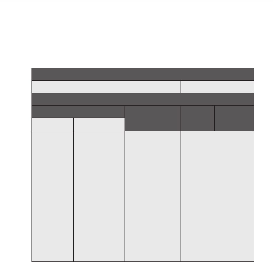
102
b. Description
A Geotechnical Report may be required for some Bid Packages, if the project requires extensive
excavation or is located on a unique and possibly contaminated site, or for other reasons
determined by the Project Team. Ensure that the Geotechnical Report is noted in the Table of
Contents as an Appendix Document.
D. METHODS OF PROCUREMENT
1) SINGLE CONTRACT BID VS. MULTIPLE PRIME CONTRACT BID
Bids may be procured as either Single Contract or Multiple Prime Contract Projects. Consultant shall
coordinate with DDC PM to determine how the project will be procured to prepare the appropriate
documentation. It is imperative that the Consultant and Project Team establish how the project is procured
prior to the Design phase, to avoid potential delays to the schedule later.
The following table lays out which projects can be bid as Single Contract, and which projects must be bid
as Multiple Prime Contract:
Question 1: How much does this project cost?
Above $3 Million Below $3 Million
Qq Question 2: Where is this project located?
City-Owned Property Non-
City-Owned
Property
City-
Owned
Property
Non-
City-Owned
Property
Renovation New Building
Bid as
RENOVATION
PLA:
Format all
documents
as one single
contract. *
Bid as NEW
CONSTRUCTION
PLA:
Format all
documents as one
single contract.
A Feasibility Study
shall be required
to establish the
applicability of
project to the PLA.
Determination
should be
established prior to
the Construction
Document Phase
to avoid delays.
MULTI-CONTRACT
WICKS:
Format all
documents as 4
separate contracts
as follows:
Contract #1: General
Construction
Contract # 2:
Plumbing
Contract #3: HVAC
& Fire Protection
Contract #4:
Electrical
REVISED
(SINGLE CONTRACT)
WICKS:
Format all documents as a
single contract.*,**
* DDC Policy requires all City Owned projects with estimated costs equal to or above $2.5 million to
bid as Renovation PLA, in case bids come in higher than expected (ie- above $3 million).
** DDC Policy requires all Non-City Owned projects with estimated costs equal to or above $2.5
million to bid as Multi-Contract, in case bids come in higher than expected (ie- above $3 million).
102
CHAPTER 05: BID PACKAGING REQUIREMENTS
D. METHODS OF PROCUREMENT

103
a. The first factor in determining whether the project shall be bid as Single Contract or Multiple Prime
Contract is the cost. If the estimated project cost is less than $3 million, the project will be bid as a
Single Contract, regardless of location.
b. If the estimated project cost exceeds $3 million, the next step is to determine whether or not it is
located on City-Owned property.
i. The project may use the Project Labor Agreement (PLA) and bid to a Single Contract,
as long as the cost of project exceeds $3 million and meets the criteria below. Although
the threshold Is $3 million, if a project is estimated to cost at least $2.5 million, it is
anticipated that the bids may come in at or above $3 million. As such, it is recommended
for projects estimated to cost at least $2.5 million to anticipate bidding to Multiple Prime
Contracts
If the project involves the renovation of an existing building or structure, the project shall
be bid using the PLA for Renovation.
1. There are currently two types of Project Labor Agreements:
a. The PLA for Renovation:
If the project involves the renovation of an existing building or structure, the
project shall be bid using the PLA for Renovation.
b. The PLA for New Construction
If the project consists of building an entirely new structure, the project may be
bid using the PLA for New Construction, assuming that the Project Team has
conducted a Feasibility Study that has been approved by DDC Law.
Whereas renovation projects can use the PLA automatically, new construction
projects must first be approved for PLA (and subsequently, for Single Contract)
bid.
ii. If a project is located on Non-City Owned property, it cannot be bid using the PLA,
and must be bid using Wick’s Law. Projects with costs that exceed $3 million must
bid as Multi-Contract Wick's Law, which separates out the four major trades (General
Construction, Plumbing, Mechanical and Electrical Work).
1. There are two types of Wicks Law Projects:
a. Revised Single Contracts
Used for projects whose total budget will be less than $3 million.
b. Multiple Prime Contract Projects
The threshold is $3 million; however, similar to the PLA, if a project is
estimated to cost at least $2.5 million, it is anticipated that the bids may come
in at or above $3 million. As such, it is recommended for projects estimated to
cost at least $2.5 million to anticipate bidding to Multiple Prime Contracts.
c. The DDC Project Manager and Team Leader will establish with the Consultant if the project
shall be prepared as a Multiple Prime Contract Project or a Single Contract Project. For Multiple
Prime Contract Projects, or where applicable, adherence to Wick’s Law requires that the
Consultant prepare separate sets of drawings and cost estimates for four separate contracts.
The specifications shall be inclusive of all contracts but may reference the four separate Prime
Contractors. The specifications and Table of Contents shall organize the sections as per separate
contract. (Coordinate with DDC PM for latest version of drawing and table of contents for Multiple
103
05
CHAPTER 05: BID PACKAGING REQUIREMENTS
D. METHODS OF PROCUREMENT

104
Prime Contract Projects). These documents, unless directed otherwise by DDC PM, shall be
organized as follows:
i. Contract #1: General Construction work, including site work and vertical transportation.
ii. Contract #2: Plumbing work, including standpipe system, if required.
iii. Contract #3: Heating, Ventilating, Air Conditioning, and Fire Protection work, including
sprinkler systems, as well as combined standpipe system, if required. Note: The sprinkler
system work, which is part of Contract No. 3, shall be shown and detailed on drawings
separate from all other work within that contract.
iv. Contract #4: Electrical work, fire alarm, data & telecommunications systems, A/V
systems.
2) OPEN COMPETITIVE BID VS. PRE-QUALIFIED LIST (PQL) BID
Bids may be procured to either the general public (as an open competitive bid) or to a select group, or list,
of Pre-Qualified bidders. The Consultant shall coordinate with the DDC PM to determine how the project
will be procured in order to prepare the appropriate documentation.
a. Bids procured to the general public may require additional Special Experience requirements for
the prime bidder(s). Special Experience requirements, as noted earlier in the chapter, must be
approved by DDC Law and DDC ACCO, and the Consultant shall be required to provide appropriate
justification.
b. Bids procured to a Pre-Qualified List (PQL) of bidders will take the place of Special Experience
requirements for the prime bidder(s). Since the bidders here have already been vetted and approved
to work on City projects, the Bid and Award Phase may be significantly shorter. Pre-Qualified Lists
may be for work on roofs, landmark buildings, or general construction projects (or others as may be
applicable). The DDC PM, working with the Project Team and Consultant, shall decide which PQL is
applicable to their specific project.
c. In order to bid to a PQL, the DDC PM must seek approval from DDC ACCO. At this time, the DDC
PM may require certain documents from the Consultant, including the cost estimate and detailed
project description.
E. DDC SPECIFICATION
REQUIREMENTS
Review all Bid Package contents in Section B. Bid Package Components.
1) DDC OMS (OFFICE MASTER SPECIFICATIONS)
As directed, the Consultant and all sub-consultants shall use DDC’s Office Master Specifications
(OMS) system, which utilizes a commercial software tool (Deltek e-SPECS) with DDC cloud-hosted
project storage designed to generate project-specific technical specifications in compliance with DDC’s
requirements. DDC will provide the Consultant team with access to the system including log-in credentials,
training materials, and technical support. All required software will be available as a free download. The
Consultant and all sub-consultants shall comply with the requirements in the latest version of DDC’s
Te ch n ica l S p ec i fi cat io n In s t ruc ti o n s ( TS I ) w h i ch is f ull y c o or d i na t e d w it h O M S .
104
CHAPTER 05: BID PACKAGING REQUIREMENTS
E. DDC SPECIFICATION REQUIREMENTS

105
2) SPECIFICATIONS AND TABLE OF CONTENTS
a. Technical Specification Instructions
It is the Consultant’s responsibility to download, review and comply with the requirements in the
latest version of DDC’s Technical Specification Instructions (TSI).
b. Format
All technical specifications must comply with all requirements of this section. Specification sections
developed from sources other than the DDC Office Master will not be accepted, unless approved in
advance by the Deputy Director of Bid Packaging. The specifications must be delivered to the DDC
PM as follows:
i. One single, combined original PDF document printed directly from the e-SPECS
software, and
Ii. Fully edited specifications accessible within the e-SPECS software / OMS system.
c. Description
Te ch n ica l s p ec i fi cat io n s ( a n d t he i r c o r res po n d in g Tabl es o f C o nte nt s ) w i l l b e re qu i r ed f or al l Bi d
Packages.
i. The DDC OMS specifications are Masterspec-derived and formatted per the most
current CSI numbers and headings. They are generated with DDC formatted headers
and footers. Section text has been edited to revise contract language in accordance
with DDC standards. All submissions must include an issue date, which must be
updated for each resubmission.
ii. The specifications must be inclusive of all items in the construction contract; however,
items which are not capitally eligible must be omitted. These items include (but are not
limited to) maintenance agreements, movable furniture, and spare parts, unless required
by code. Coordinate with DDC PM for full list of eligible and non-eligible scope items.
iii. All Division 1 General Requirements sections correspond to the DDC General
Conditions, which are included in Volume 2 as a reference for bidders with all contracts.
As a result, Consultant must not include any Division 1 specification sections with the
exception of Section 019119.43 "Exterior Enclosure Commissioning" for projects that
require Building Enclosure Commissioning.
iv. Similarly, all contract-related language (regarding payments, indemnification, bidding
procedures, etc.) are included in Volume 2 as a reference for bidders with all
contracts. Specifications are to be technical in nature; Consultant must review and be
knowledgeable of the Standard Construction Contract and the Information to Bidders by
coordinating with DDC PM for latest versions.
v. All specifications must include performance information for products, and all sections
that call out manufactured products must include at least two additional manufacturers
that offer comparable products, followed by the term “or approved equal.” They must
comply with governmental and legal requirements regarding public procurement; these
include, without limitation, the Competitive Bidding Laws of the State of New York, the
NYC Procurement Policy Board, Rules of the City of New York, and the DDC General
Conditions. To ensure compliance, it is essential that Consultants prepare specifications
that are clear, accurate, and in accordance with the criteria set forth below. Accordingly,
specifications shall:
1. Permit maximum competition
2. For Multiple Prime Contracts (Wicks), permit the separate, competitive sealed
bidding of each prime construction trade.
105
05
CHAPTER 05: BID PACKAGING REQUIREMENTS
E. DDC SPECIFICATION REQUIREMENTS
106
3. Clearly describe the City’s requirements without favoritism toward any Contractor,
supplier, or manufacturer, or to a supplier’s goods and/or services.
4. Emphasize functional or performance criteria. Requirements establishing the
significant qualities related to type, function, in-service performance, physical
properties, as well as other special features and requirements must always be
clearly described in Part 2 of the specifications. Because DDC awards contracts
to the lowest responsible bidder, it is important that functional/performance
specifications are tightly written using acceptable commercial standards to help
ensure the quality of the job.
5. Unless approved in advance by DDC ACCO, sole-source proprietary items are not
permitted. Refer to Section C5 of this chapter for additional information.
vi. Nomenclature
Incorrect nomenclature from the private sector or other government entities is not
acceptable for documents submitted to DDC. Specification text in the OMS has
been pre-edited to remove such references. Any new text must conform to the same
requirements as described below. Refer to the Technical Specifications Instructions (TSI)
for additional nomenclature and terminology editing guidance.
1. City of New York
References to “Owner” (or other agency or authority) as an entity should read “City
of New York” for all matters related to property and payments.
2. Commissioner
References to “Architect,” or “Engineer” should read “Commissioner.” References
to “Owner” for verification, certification, selection, approval, etc. should read
“Commissioner.”
3. Engineering Services
References to “Delegated Design” should read “Engineering Services.” Note that
all shop drawings and other submittals must be reviewed and approved “by the
Commissioner”. The Consultant must remain the Designer of Record (Architect of
Record and/or Engineer of Record) and the Contractor’s engineer may not assume
that responsibility. Specifications where Engineering Services are specified must
provide all required performance and design criteria such that the Contractor’s
Engineer is not required to make any design assumptions. Engineering Services
provided must meet all the requirements of the NYC Codes, rules, procurement
requirements, and regulations.
4. Authorities Having Jurisdiction (AHJ)
References to “Authority” or “Authorities Having Jurisdiction” must be revised to the
applicable Code, Standard, Entity, Department, or Agency.
vii. Moreover, the Consultant must ensure that all specification sections are fully edited
and relevant to their specific project. The Consultant is responsible for all specification
information submitted including those produced by its sub-consultants. Do not include
references to sponsors, clients, items or sections that are not applicable to the scope
of the project at hand. It is imperative that, prior to submitting the specifications, the
Consultant inspect all documents for adherence to all DDC requirements, completeness,
and accuracy.
106
CHAPTER 05: BID PACKAGING REQUIREMENTS
E. DDC SPECIFICATION REQUIREMENTS

107
F. CONSULTANT WORK SESSIONS
The Consultant and sub-consultants responsible for writing technical specifications shall attend regular sessions
with the Bid Packaging team starting at the CD Kickoff; however, training sessions on utilizing the OMS and
the e-SPECS software will be scheduled with Consultants and sub-consultants for all new projects prior to start
of CD Phase. Sessions shall occur bi-weekly or as mandated by the DDC Bid Packaging team. During these
work sessions, drafts of all technical specifications shall be submitted for review as directed by the DDC Bid
Packaging team. For more on Design Review, Sign-Off, and Final Acceptance of Construction Documents and
the Bid Package, see Chapter 02: Overview of the Design Process.
107
05
CHAPTER 05: BID PACKAGING REQUIREMENTS
F. C ON SU LTANT WOR K S E S SIONS
108108

109
CHAPTER 06:
DESIGN CRITERIA
109
A. GENERAL DESIGN APPROACH
B. ACCESSIBILITY
C. HISTORIC PRESERVATION
D. BUILDING ELEMENTS AND SYSTEMS
110

111
A. GENERAL DESIGN APPROACH
All systems and components for the urban planning, architectural design, landscape design, and engineering
of public projects must be designed to meet and in some cases exceed code requirements, while adhering to
commonly established industry standards for quality, performance, materiality, fabrication, and installation.
Individual disciplines and systems must not be considered separately during design or documentation, but in
an integrated and therefore comprehensive way. Project design should always strive to be holistic in order
to creatively balance cost, schedule, and program requirements, operations and maintenance practices,
sustainability and resilience, and performance and innovation. To respect public investment, the project must
achieve a good fit through a design that is well-suited to its intended use and reflects the present and future
needs of agency sponsors, end users, and communities.
In addition to any project-specific criteria, the following priorities must be applied across all disciplines by during
the development of the project:
1) COLLABORATIVE AND TRANSPARENT
The design of public buildings and spaces requires a transparent, collaborative, and inclusive process
that values all voices. All stakeholders, including the project’s end users, the greater community, and
all participating city agencies, must be offered an opportunity to meaningfully contribute to a common
vision for the project. Through public outreach and interagency coordination, the process must promote
discourse, exemplify accessible government, and inspire pride and a sense of ownership in the community.
2) CIVIC AND COMMUNITY ORIENTED
a. Every neighborhood in New York City possesses a unique history and character that contribute
to its sense of place. The design of public projects must actively engage the neighborhoods and
communities in which they are built by respecting and responding to their existing context.
b. Site design should reinforce community connectivity by responding to existing pedestrian routes
and nearby amenities, mass transit, parks, and other local destinations. The overall project design
should enliven the pedestrian experience with creative massing and façade articulation, an
engaging ground floor, and visible and prominent entrances and open spaces.
c. Project design must be guided by Sponsor Agency and municipal planning strategies such as
previously approved master plans, Zoning Resolution Determinations, and ULURP agreements
where applicable. Special consideration must be given to both officially designated landmarks as
well as landmark quality structures.
d. Project design should honor history and culture and convey community identity through a design
that contributes to the character of the neighborhood with its form, materials, details, lighting, and
landscape. It should incorporate art that reflects and enriches local culture and identity.
e. Related Sections and Resources:
i. Chapter 06: Historic Preservation
ii. Chapter 09: Percent for Art
iii. Chapter 10: Regulatory Approvals (See information on NYC Community Boards, Public
Design Commission, Landmarks Preservation Commission)
iv. CEQR Technical Manual (The Mayor’s Office of Environmental Coordination)https://
www1.nyc.gov/assets/oec/technical-manual/2020_ceqr_technical_manual.pdf
06
CHAPTER 06: DESIGN CRITERIA
A. GENERAL DESIGN APPROACH
112
3) INCLUSIVE, HEALTHY, AND SAFE
a. Public buildings and spaces must support the health, dignity, and well-being of all New Yorkers,
inclusive of all racial, ethnic, gender, sexual, religious, and cultural identities, and physical, social,
cognitive, and mental abilities. All spaces must be equitable and accessible and should be designed
to exceed minimum code requirements whenever feasible. Inaccessible public design elements of
any kind will not be permitted.
b. Whether a facility is intended for public use or agency operations, it must enable every individual to
feel welcome and valued, comfortable, and secure. Public spaces, entrances, and lobbies should be
readily perceptible from the street with a clear sense of orientation. They should be well-lit, easy and
intuitive to navigate, and supported by clear and consistent signage that is accessible to people of
different ages and cultures. They must create a welcoming atmosphere with an appropriate level of
security that has been thoughtfully integrated with the project design.
c. The project design should create indoor environments with healthy air quality, comfortable
temperatures, noise- mitigating acoustics, suitable and variable natural and artificial lighting, and
high-quality, sustainable materials.
d. Both indoor and outdoor spaces should be designed to promote physical activity and inspire
movement, provide access to daylight, fresh air, and drinking water, and provide visual connections
to nature.
e. Related Sections and Resources:
i. Chapter 06: Accessibility
ii. Inclusive Design Guidelines (Mayor’s Office for People with Disabilities)
iii. Inclusive Design Guidelines: Sports & Recreation (Mayor’s Office for People with
Disabilities) https://www1.nyc.gov/site/mopd/initiatives/inclusive-design-guidelines.
page
iv. Aging in Place Guide for Building Owners (NYC Department for the Aging) https://
ihcdhome.humancentereddesign.org/pdf/Aging%20in%20Place%20guide%20for%20
Building%20Owners.pdf
v. Universal Design New York (DDC) https://www1.nyc.gov/assets/ddc/downloads/
publications/guides-manuals/universal-design-ny.pdf
vi. Active Design Guidelines (DDC) https://www1.nyc.gov/assets/planning/download/
pdf/plans-studies/active-design- guidelines/adguidelines.pdf
4) SUSTAINABLE AND RESILIENT
a. Systems performance should make efficient use of resources for operation and, through
benchmarking and commissioning, be capable of demonstrating that they operate as designed.
Maintenance plans must be achievable and ensure continued performance throughout each
system’s useful life.
b. The project design must consider emergent and long-term risks by planning to mitigate and
withstand the impacts of climate change and changing public health and safety conditions including
sea-level rise, intensifying storms, and extreme heat. This will include managing storm water,
offsetting the heat island effect, utilizing native vegetation, and considering short- and long-term
impacts on local and regional ecosystems, including fauna such as migratory birds.
CHAPTER 06: DESIGN CRITERIA
A. GENERAL DESIGN APPROACH

113
c. In addition to local and federal codes pertaining to flood mitigation and flood proofing, the project
design must support community resilience by designing public facilities that perform effectively
during extreme events, provide essential services to vulnerable community members, and return
easily to normal operations
d. Related Sections and Resources:
i. Chapter 07: Commissioning
ii. Chapter 08: Sustainability and Resiliency
iii. Climate Resiliency Design Guidelines (Mayor’s Office of Resiliency) https://www1.nyc.
gov/assets/orr/pdf/NYC_Climate_Resiliency_Design_Guidelines_v4-0.pdf
iv. Sustainable New York (DDC) https://www1.nyc.gov/assets/ddc/downloads/
publications/about-ddc/sustainable-new-york.pdf
v. Geothermal Heat Pump Manual (DDC) https://www1.nyc.gov/assets/ddc/downloads/
Sustainable/GeothermalHeatPumpManual.pdf
vi. Water Matters (DDC) https://www1.nyc.gov/assets/ddc/downloads/publications/
guides-manuals/ddc-water-matters.pdf
5) FUNCTIONAL, DURABLE, AND COST-SENSITIVE
a. The project team should select high-quality, durable materials, equipment and building systems that
are simple to operate, maintain, update, and replace when needed. These materials and systems
should be readily available and easily buildable with local construction practices to minimize lead
times, eliminate cost overruns, and prevent delays.
b. The project team should integrate functionality by thoughtfully incorporating building systems and
services into the overall design, including security, lighting, mechanical equipment, utilities, and
waste disposal, and by screening equipment from public view.
c. The project’s space planning must provide unimpeded access and required minimum clearances
per manufacturer recommendations and OSHA for the service, repair, and eventual removal and
replacement of equipment without removal of exterior walls or significant impact on adjacent
equipment and building occupants. This includes major components such as switchboards,
motor control centers, boilers, chillers, cooling towers, pumps and air-handling units as well as
ancillary components such as valves, cleanouts and individual equipment controls. All spaces must
be designed with reasonable construction tolerances to ensure compliance with all legal and
programmatic spatial requirements.
d. When proposing novel or innovative building systems, design features, or products, the project team
must analyze and compare initial cost, long-term operating costs, and maintenance requirements in
comparison to industry standard products and practices. These recommendations must be reviewed
with both the Sponsor Agency and their facilities engineers to solicit input and manage operational
expectations. The project team may be required to prepare supplemental manuals to facilitate the
operation and maintenance of the proposed element.
e. Related Sections and Resources:
i. Chapter 06: Accessibility (Sections A-G: Elements)
06
CHAPTER 06: DESIGN CRITERIA
A. GENERAL DESIGN APPROACH

114
CHAPTER 06: DESIGN CRITERIA
B. ACCESSIBILITY
B. ACCESSIBILITY
The Consultant is responsible for the design and construction of projects so that the building and/or site is
readily accessible to and usable by individuals with disabilities. The Consultant is responsible for complying with
all applicable local, state and federal requirements, including but not limited to, the accessibility requirements
set forth in Chapter 11 of the NYC Building Code and its associated Technical Reference Standard ICC
A117.1-2009, and the 2010 ADA Standards for Accessible Design (the “2010 ADA Standards”) as well as
all other requirements included in the Accessibility Standards, as defined in section c. below. The Consultant
is encouraged to utilize United States Access Board Guidelines, whenever possible, as an additional design
resource. Conformance with only one code or standard does not fulfill the obligation of the Consultant. Where
there is a conflict or inconsistency between the requirements, the Consultant will ensure compliance with the
more restrictive requirement. Obtaining approvals and permits from the Department of Buildings or any other City
agency does not waive the Consultant’s obligation to ensure the project’s design and construction is compliant
with all applicable local, state and federal accessibility requirements.
1) SCOPING
The Consultant shall review the scope of work provided in the FEP Report/Project Objectives and analyze
the scoping provisions and triggers within the NYC Building Code and 2010 ADA Standards to ensure the
design fully meets these accessibility requirements accordingly. The Consultant must monitor compliance
of the design and its documentation during all design and construction phases. All new buildings must be
fully accessible, to the extent established by such codes and standards. When altering existing buildings,
the Consultant is responsible for verifying that the scope of work in the FEP Report/PO fully addresses
the requirements of the NYC Building Code or 2010 ADA Standards, and must notify DDC in writing of
any potential omissions or conflicts. The Consultant shall evaluate whether ADA Path of Travel (28 CFR
35.151(b)) is triggered by any alteration to a primary function area. If an area containing a primary function
has been altered without providing an accessible path to that area, and subsequent alterations of that
area, or a different area on the same path, are undertaken within three years of the original alteration,
the total cost of alterations to the primary function areas on that path of travel during the preceding
three-year period shall be considered in determining whether the cost of making that path accessible
is disproportionate. The Consultant shall also evaluate whether the building must be fully accessible
due to a change in the dominant occupancy/use, or based on the value of the alteration, as outlined in
NYC Building Code Sections 1101.3.1 and 1101.3.2. Once the required level of accessibility has been
evaluated, the Consultant is responsible for proper execution of the technical requirements.
2) TECHNICAL REQUIREMENTS
The Consultant is responsible for ensuring all building components are designed and constructed in
compliance with Accessibility Standards, as required by the project scope. The Consultant is advised to
provide adequate construction tolerances to ensure ordinary construction inaccuracies do not result in a
non-compliant built condition.
3) ACCESSIBILITY STANDARDS
To ensure capital construction projects are readily accessible to and usable by individuals with disabilities,
and to prevent the unlawful discrimination based on disability, the term ‘Accessibility Standards’ used
throughout this document shall mean the following, and are inclusive of current versions of all the
following:
a. The New York City Construction Codes, including Chapter 11 of the NYC Building Code;

115
06
CHAPTER 06: DESIGN CRITERIA
C. HISTORIC PRESERVATION
b. Accessible and Usable Buildings and Facilities, ICC A117.1 2009 Edition;
c. NYC Charter §224.3, regarding induction loop systems;
d. The Americans with Disabilities Act, 42 U.S. Code §12101 et seq. and regulations implementing
Title II of the Americans with Disabilities Act, 28 CFR §35.101 et seq., with particular regard
to §35.151 “New construction and alterations,” and including, but not limited to, path of travel
requirements associated with alteration work;
e. The 2010 ADA Standards for Accessible Design for State and Local Government Facilities Title II,
with particular regard to §104.1, concerning construction and manufacturing tolerances;
f. Section 504 of the Rehabilitation Act, 29 U.S. Code §794, and implementing regulations;
g. United States Access Board issued accessibility guidelines;
h. The New York State Human Rights Law, Executive Law §291 et seq., with particular regard to
§296(2)(c);
i. The New York City Human Rights Law, Administrative Code §8-101 et seq., with particular regard
to §8- 107(15); and
j. The Fair Housing Act, 42 U.S. Code §3601 et seq., as amended by the Fair Housing Amendments
of 1988, and implementing regulations at 24 CFR Part 100.
C. HISTORIC PRESERVATION
1) INTRODUCTION TO HISTORIC PRESERVATION
It is critical for preservation expertise to be brought to bear at an early planning stage. Early decisions
that define a project’s direction can have serious implications for the historic and architectural integrity of
a building or site beyond technical preservation and materials conservation. Historic preservation design
criteria apply to work on structures, interiors, sites, streetscapes and works of art that fall into three
categories based on the regulatory framework:
a. Designated New York City landmarks, interiors, scenic landmarks, and properties in designated
historic districts -- including all features within the boundaries of scenic landmarks and historic
districts -- are subject to regulatory oversight by the NYC Landmarks Preservation Commission
(LPC). The Commission makes little distinction in regulatory procedure or standards between
individual landmarks and properties within historic districts.
b. Properties that are not designated by the LPC but are of landmark quality, including those listed
on or eligible for the New York State or National Registers of Historic Places, or eligible for local
designation by virtue of their significant historic, cultural, architectural or landscape features, are not
subject to regulatory oversight by the LPC. The determination of whether properties affected by a
project are landmark quality is made by DDC’s Historic Preservation Office (HPO) in consultation
with the New York State Historic Preservation Office and the Landmarks Preservation Commission.
c. Projects affecting properties in both above categories may require review by the NY State Historic
Preservation Office (SHPO) and under the City Environmental Quality Review Act (CEQR) or other
environmental review laws, depending on funding sources and potential for adverse impacts on
historic resources. Projects affecting works of art will also require review by the Public Design
Commission.
116
CHAPTER 06: DESIGN CRITERIA
C. HISTORIC PRESERVATION
2) STANDARDS AND GUIDELINES
Regardless of the outside regulatory framework, all projects affecting historic properties are reviewed
by the DDC Historic Preservation Office for conformance with historic preservation standards, generally
defined by LPC rules and guidelines and/or the Secretary of the Interior’s Standards for treatment of
historic properties. The Consultant must obtain from the HPO the latest published guidelines, standards,
rules, application forms and instructions pertaining to historic preservation from any agency having
jurisdiction over a designated property. The scope of the project will determine the most appropriate way to
apply preservation standards. Every effort shall be made to achieve full compliance with the standards and
to protect the historic and architectural features which support the designation, listing, or eligibility of the
property.
3) CONSULTANT SERVICES
The extent of services described below may vary according to the overall scope of work and regulatory
framework. Other services may be required and may be more fully described in the Project Objectives-
Scope of Work or Task Order. Typically, required services include:
a. Research
Documentary, historical, and field research sufficient to inform the project scope and intent will
provide a sound basis for design decisions and help in evaluating conditions exposed during probes
and/or construction.
b. Evaluation of Significance
The Consultant is expected to prepare an evaluation of the relative importance of features relevant
to preservation. The evaluation shall be based on research, and on an inventory of features such
as spaces, materials, structural and other building systems, equipment, furnishings, stylistic details,
craftsmanship, works of art, as well as historic or cultural significance.
c. Existing Conditions
The Consultant shall provide a conditions report based on observation, interviews, probes and
tests. The Consultant is expected to identify, plan and oversee probes and tests, to provide detailed
reports, and to incorporate results into the design strategy.
d. Documentation
In the absence of existing measured drawings, the Consultant shall produce a set of base
measured drawings of historical features in the areas of work included in the scope. Throughout
the project, the Consultant shall keep a Record of all changes to existing and original features
including materials, methods, design intent, and detailing. The Consultant shall provide photographic
documentation of conditions and activities throughout the project.
e. Design Options
All design options shall respect the historic and architectural integrity of the structure or site. At
least one option must fully conform to applicable LPC guidelines and rules and the Secretary of
the Interior’s Standards. Any project affecting a historic resource, even if it primarily involves non-
architectural trades or is not specifically for historic preservation, can have preservation implications,
which must be considered in the design. Each scheme must fully explain the approach and the
consequences as they relate to preservation issues. Each scheme must also be accompanied by a
cost estimate and must include a life-cycle analysis with long-term cost/benefit scenarios.

117
06
f. Salvage of Historic Artifacts
Architecturally and historically significant features and fixtures such as sculpture, doors, woodwork,
light fixtures, and furnishings should be incorporated into the project, preferably in their original
locations or elsewhere on the project site. If a reuse on site cannot be found, the Consultant is to
arrange for their relocation or reuse by the sponsor agency. The contract documents shall reflect
these determinations.
g. Application for Eligibility
The Consultant may be required to prepare an application for the determination of eligibility for the
National or State Historic Register as an additional service.
h. Special Experience Requirements
When the construction contract calls for special experience requirements, the Consultant shall
assist in the review and verification of the special experience qualifications submitted by the
Contractor and/or proposed sub- contractors. The Consultant may be required to participate in site
visits to view qualifying work.
i. Historic Preservation Specialists
The Consultant shall provide a full range of preservation and conservation services by qualified
experts. These experts shall be used wherever appropriate, in all phases of the project, including
construction. The level of their participation and the extent of their responsibility shall be clearly
defined at the beginning of the project. Specialists who may be required include, but are not limited
to: historians, archaeologists, architectural and art conservators, materials specialists, historic
structural and systems engineers, historic landscape architects, and advisors on special crafts
associated with historic properties.
j. Maintenance Handbook
The Consultant shall provide a maintenance handbook addressing all features and finishes related
to the historic preservation work. These may be conserved and restored features, new features that
replicate historic features, or other features and finishes that are complementary to the work and
contribute to the historic and architectural character of the building or site. The handbook should
include requirements and recommendations from manufacturers and suppliers of any materials or
fixtures.
CHAPTER 06: DESIGN CRITERIA
C. HISTORIC PRESERVATION

118
CHAPTER 06: DESIGN CRITERIA
D. BUILDING ELEMENTS AND SYSTEMS
D. BUILDING ELEMENTS AND
SYSTEMS
The following technical criteria must be applied to the design of building elements and systems in the project.
This criteria is presented in CSI's Uniformat classification system, and is characterized by a description of
performative and functional requirements without regard to the materials and methods used to accomplish them.
A SUBSTRUCTURE
A10 FOUNDATIONS
A1000 Foundations General
1. Foundation Type
The Consultant must perform investigative work on the site including but not limited
to borings and evaluate this data to determine the most suitable and economical
type of foundation. The foundation must be properly designed, detailed, and
specified on the structural drawings and specifications.
2. Ground Water
The Consultant must evaluate the ground/flood water conditions indicated in the
Geotechnical report. If subsurface waterproofing is required, these details must be
shown on the architectural drawings, coordinated, and schematically shown on the
structural drawings
3. Settlement
The foundations must be designed to minimize overall as well as differential
settlements. For utility lines where such settlement could have detrimental effects
on facility operations, health, and safety, the settlement criteria must be more
stringent. This is to be coordinated by the Design-Builder with other trades, as
applicable.
4. Unsuitable Soils
Where the existing soils are not suitable for supporting a slab on grade, such floor
systems.
5. Vibrations and Monitoring
The Consultant must advise on the requirements for monitoring the structure and
any affected structures in the vicinity and provide relevant guidance in the notes or
on the drawings.
A1020 Special Foundations
A1020.10 Driven Piles
1. The effect of pile driving operations on adjacent properties must be taken into
consideration during design and should be reviewed with DDC. Pile types not
mentioned in the NYC Building Code must be specified only after appropriate
design analysis is performed and approval from the DOB is obtained. DOB
determination is required prior to Design Development Phase kick-off.

119
06
CHAPTER 06: DESIGN CRITERIA
D. BUILDING ELEMENTS AND SYSTEMS
A1020.50 Underpinning
1. Where the project is located adjacent to existing structures, the Consultant must
make every effort to avoid or minimize the need for underpinning. If underpinning is
found necessary, the following recommendations must be adhered to:
a. Where underpinning may be required, the Consultant must notify the
Project Manager at the Schematic Design phase to contact the adjacent
property Owner and coordinate all issues associated with underpinning.
b. The design of the underpinning is the responsibility of the Consultant and
must be designed by a Professional Engineer, licensed in the State of
New York, and retained by the Consultant. The drawings must be signed
and sealed by the Structural Engineer.
c. The Consultant must review the underpinning for its impact on the new
and existing construction and for conformance to their recommendations.
d. The Consultant is solely responsible for monitoring the conditions of the
adjacent buildings and other structures affected by the underpinning
during construction.
e. Underpinning must be identified and listed as a special inspection.
f. The Consultant must evaluate and monitor adjacent or affected historic
properties.
A40 SLABS ON GRADE
A4000 Slabs On Grade – General
1. The Consultant must design, detail, and adequately specify all new slabs on grade
to minimize or eliminate cracking and curling. Structural Synthetic Macro-Fibers
should be used as a substitute for welded wire fabric reinforcement to minimize
cracking in concrete from both plastic shrinkage and temperature shrinkage. The
design must meet the requirements of ACI 360 R, Design of Slabs on Grade, and
other applicable guidelines.
A90 SUBSTRUCTURE RELATED ACTIVITIES
1. Subsurface Investigation
In addition to providing for a suitable foundation solution, the Consultant is
expected to use best professional judgment and experience to determine a soil
exploration program that will reasonably clarify soil related work. The Consultant is
responsible for the geotechnical analysis and engineering of the project.
a. Office of Geotechnical Investigations (OGI)
At the earliest project stage, the Consultant shall consult through the
DDC Project Manager with the DDC OGI to determine a preliminary
number of borings, their location, and other required investigations.
Contact with the OGI shall be maintained throughout site exploration.
The Geotechnical Section shall be represented at the Design Kick-off
Meeting.
120
b. Site Visits
All projects that require excavation and foundation work will be visited
at the start of Pre-Schematic or Schematic Design by the Consultant’s
Structural Engineer or Geotechnical Engineer. This site visit is a
contractual obligation. Based on the project requirements and as result of
this field visit the program of soil exploration shall be initiated.
c. Soil Exploration Program
The soil exploration program should enable the determination of the
optimal foundation solution as well as the reduction of uncertainty during
construction. DDC does not place a maximum limit on the number of
borings to be taken. The number and type of investigations should
be based on reasonable economic and engineering decisions and in
accordance with the NYC Building Code.
d. Additional Borings
When the Consultant finds that the preliminary borings are not sufficient
to provide information for design and construction, additional borings
shall be ordered as soon as possible to prevent any potential delay to the
project schedule.
B SHELL
B10 SUPERSTRUCTURE
1. Superstructure Types
The Consultant must evaluate and design structural systems that are
economical, efficient, durable, sustainable and flexible for future modifications
and reconfigurations of spaces meeting the loading, serviceability, durability
and vibration requirements of the Building Code, ASCE 7 and other applicable
guidelines. The Consultant must evaluate and design lateral force resisting systems
(LFRS) that are efficient and economical and appropriate for a gravity structural
framing system.
B20 EXTERIOR VERTICAL ENCLOSURES
B2010 Exterior Wall
B2010.00 Exterior Wall – General
1. Cavity Wall Air Space and Insulation
a. Cavities exceeding the code maximum will require analysis / calculations
to be performed for the tie anchors.
b. Cavity walls are designed not only to guide any moisture occurring in
the cavity to move downward to the flashing and weep vents, but also to
allow a certain flow of air throughout the cavity. Recommend providing
a 2- inch minimum clear drainage cavity (not including the insulation) to
be effective, to allow for proper construction of the wall, and to minimize
mortar fins, droppings and bridging.
CHAPTER 06: DESIGN CRITERIA
D. BUILDING ELEMENTS AND SYSTEMS

121
06
c. Clearly indicate insulation attachment method either mechanically or
adhered to masonry backup. Friction fitting rigid insulation between
horizontal reinforcement is not an acceptable solution.
d. If constructing cavity walls, provide continuous flashing at the bottom of
the cavity and wherever the cavity is interrupted by elements such as shelf
angles, lintels and penetrations.
B2010.10 Exterior Cladding
1. General
a. Provide for continuity of the thermal and moisture protection layers of the
exterior vertical enclosure and its connection to the horizontal enclosure.
b. Design envelope sections to prevent condensation on interior surfaces of
or within wall/roof sections that would support mold growth.
2. Materials
The Consultant must use materials that are cost effective, durable, easily
maintained, and appropriate to the context of the project site. For renovations and
additions, the qualities of the new exterior materials must compliment or match the
existing materials when appropriate.
3. Loads
The Structural engineer must provide cladding design loads necessary for the
design of the exterior building envelope to the architect. The structural engineer
must also provide the architect with relevant building deflections necessary for
the design of cladding details and must recommend location of the expansion and
construction joints.
The Consultant is responsible for the strength and code compliance of all masonry
elements, including brick, block, stone, and mortar. Attachment and reinforcement
of masonry components, especially parapets, must be clearly detailed on the
drawings. Special structural investigations must be conducted on landmarks and
landmark quality structures.
4. Anti-Graffiti Coatings
Sponsor Agencies may require sealants to protect against graffiti. When specifying
sealants, the Consultant must evaluate the risks of long-term damage to materials,
particularly masonry historic structures and landmarks. Knowledge of prior coatings
on the building is required, as are material samples with and without proposed
sealants. Only non-toxic sealants must be specified. Detailed programmatic
requirements will be addressed for such projects in the specific project
requirements.
B2010.30 Exterior Wall Interior Skin
1. Where used, build with glass mat or moisture/mold resistant, Type X gypsum wall
board for the interior face of exterior walls. On exterior walls, use only interior wall
finishes that allow water vapor within the wall to escape into the conditioned space.
Do not use vinyl wall coverings, oil-based paint, and other vapor-resistant materials
as interior finishes for exterior walls.
CHAPTER 06: DESIGN CRITERIA
D. BUILDING ELEMENTS AND SYSTEMS
122
B2010.90 Exterior Wall Openings Supplementary Components
1. Flashing (076000)
a. The Consultant must show flashing details for installation for lapping /
sealing, terminations and end dams, inside corners and outside corners
(either field formed or prefabricated), wall to roof line, base flashing
and copings. Isometric or 3D drawings must be used to convey proper
detailing.
b. Where the flashing is not continuous, such as over and under openings
in the wall and on each side of vertical expansion joints, the ends of the
flashing should be extended beyond the jamb lines on both sides and
turned up into the head joint at least 1 in. at each end to form a dam. It is
recommended to turn up flashing into the sill joints 4”.
c. Provide weep vents and mortar net at all wall flashings.
d. Flashing materials to be chosen based on durability and compatibility with
adjacent materials. Service life of flashing should meet or exceed that of
the wall or roof assembly it is part of. Factors such as durability during
construction, corrosion, deterioration due to UV exposure, and movement
must also be part of the selection criteria. Dissimilar metals should be
avoided.
B2020 Exterior Windows
B2020.00 Exterior Windows General
1. Sponsor Agencies may require the use of security measures on windows to guard
against window vandalism and break- ins. The Consultant is encouraged to explore
an improved aesthetic for these applications using new materials, technologies, and
strategies to meet the Sponsor Agency’s need for security.
2. Select framing that includes advanced thermal breaks of polyester-reinforced
nylon.
3. Wherever possible, select systems that incorporate pressure-equalized technology.
4. Consider building energy efficiency, occupant comfort, daylighting, acoustic
performance, and security when selecting exterior window and glazing systems.
B2080 Exterior Wall Appurtences
1. Provide bird control devices per the Bird-Safe Building Guidelines, NYC Audubon,
or as required by code.
B30 EXTERIOR HORIZONTAL ENCLOSURES
B3010 Roofing
B3010.00 Roofing General
1. Construct in accordance with the recommendations of the National Roofing
Contractor Association (NRCA) Manual – Current Edition.
2. Roof-mounted equipment should be elevated as recommended in the NRCA
Roofing and Waterproofing Manual and set back from the roof edge to minimize
visibility.
CHAPTER 06: DESIGN CRITERIA
D. BUILDING ELEMENTS AND SYSTEMS

123
06
3. Do not use pitch pockets as part of the roof design.
4. No building element may be supported by the roofing system except protective
walkways manufactured specifically for use with that roofing system.
5. Provide protective walkways on the roof along routes to and around equipment for
maintenance.
B3010.50 Low Slope Roofing
1. For edge flashings and copings on low-slope roofing, follow ANSI/SPRI ES-1.
B3010.90 Roofing Supplementary Components
1. Install vapor retarder in accordance with guidance in the NRCA Roofing and
Waterproofing Manual.
2. For Roof System Related Sheet Metal Flashing use The NRCA Manual:
Architectural Metal Flashing, Condensation Control & Reroofing – 2010 and
SMACNA Architectural Sheet Metal Manual.
B3050 Horizontal Openings
B3050.10 Roof Windows and Skylights
1. Assemblies must comply with wind load testing in accordance with ASTM E 1233.
2. Skylight design must follow the guidelines of AAMA Standard 1600.
3. For the design of sloped glazing, reference the following two AAMA publications as
resources: Glass Design for Sloped Glazing and Structural Design Guidelines for
Aluminum Framed Skylights.
4. When designing for essential facilities as identified in the Specific Project
Requirements, roof window and skylight assemblies to pass ASTM E1886 missile-
impact and cyclic-pressure tests in accordance with ASTM E1996 for project's
Wind Zone for enhanced protection.
C INTERIORS
C10 INTERIOR CONSTRUCTION
C1010 Interior Partitions
1. Use cementitious wall board as a tile base.
2. Use types IR and MR and type X gypsum wallboard where applicable for high-
impact and moisture resistance per ASTM C645 and C1396.
3. Masonry partitions to be per ASTM C129, C645, C1596.
C1020 Interior Windows
1. Use insulated glazing where separating conditioned spaces.
C1030 Interior Doors
1. Per ANSI/SDI A250.8 (2017) for hollow-metal doors and frames, provide at a
minimum Heavy-Duty Doors and Frames, Level 2 or Extra-Heavy-Duty Doors
and Frames, Level 3 and Physical Performance Level A, Model 1 (full flush),
CHAPTER 06: DESIGN CRITERIA
D. BUILDING ELEMENTS AND SYSTEMS
124
with full profile welded frame construction, or as required in the Specific Project
Requirements.
C20 INTERIOR FINISHES
1. Finish materials must not adversely affect the health of workers or occupants.
Health considerations must extend to the material’s production, off-gassing during
installation, and environmental pollution engendered by the disposal process.
C2010.00 Wall Finishes
1. Provide moisture and mildew resistant interior wall finishes which are easily
maintained, and suitable in accordance with industry standards for the architectural
surface being finished.
C2030.00 Floor Finishes
1. When budget and maintenance conditions allow, flooring from renewable resources
such as linoleum, rubber, clay, or cork, and materials with high recycled content
are encouraged. Vinyl composition tile (VCT) is discouraged. For health and
maintenance reasons carpeting is discouraged. Alternative flooring should be
considered wherever suitable, and in those situations where carpet must be used,
carpet tile is preferred.
D SERVICES
D20 PLUMBING
D2000 Plumbing Performance Requirements
1. Plumbing Seismic Design
Plumbing Systems and Equipment Requiring Restraint- Plumbing natural gas
piping, motor vehicle fuel storage tankage, piping and dispensing equipment,
domestic water storage tankage, supply/return piping and heating equipment,
sanitary drainage piping and pumping equipment, vent piping, stormwater drainage
piping and pumping equipment associated with building life safety systems or other
critical plumbed equipment that must be maintained functional and operational
in the aftermath of a seismic event, must be designed for seismic forces and
adequately restrained.
2. Special Purpose Equipment Areas Served By Plumbing Systems
a. In Mechanical Equipment Rooms, potable water piping and sanitary/storm
drain piping must not be located above motor control centers, variable
frequency drives (VFD), motor disconnect switches and other mechanical
equipment controls. Where required, suitable means of protection (guards,
drain pans, pipe leak containment jacketing and leak detection) will be
provided to shield mechanical equipment from exposure to leaking and
spraying water.
b. Mechanical Equipment Rooms must be provided with floor drains and/
or other suitable means of collecting, containing, and disposing of water.
Overhead and floor mounted drain piping will be located and arranged
to maintain safe headroom and adequate walkway clearance for normal
maintenance access and service clearance.
CHAPTER 06: DESIGN CRITERIA
D. BUILDING ELEMENTS AND SYSTEMS

125
06
c. In Electrical Equipment Rooms – no potable water piping and sanitary/
storm drain piping are permitted. Where required, suitable means of
protection (guards, drain pans, pipe leak containment jacketing and leak
detection) will be provided to shield electrical equipment from exposure to
leaking and spraying water.
d. In Information Technology Equipment Rooms - no potable water piping
and sanitary/storm drain piping are permitted. Where required, suitable
means of protection (guards, drain pans, pipe leak containment jacketing
and leak detection) will be provided to shield information technology
equipment from exposure to leaking and spraying water
e. In Chemical Storage Rooms, UPS Battery Rooms and other areas with
hazardous chemical exposure environments, – an OSHA compliant
emergency eyewash station and shower will be provided. Floor drains
provided for emergency eyewash stations and shower locations will
incorporate suitable means of collecting, containing, treating, and safely
disposing of chemically contaminated water before discharge to building
drainage system and the City sanitary sewer.
f. Vertical Chases and Shafts- all potable water piping and sanitary/
storm drain piping pipes located within building vertical chases and
shafts will have accessible service drain valves with hose bibs located at
intermediate floors and the bottom of pipe risers for ease of maintenance.
Where required, provide a means of air venting and vacuum relief to allow
water to drain freely from riser piping. A floor drain will be provided at the
lowest level in each chase or shaft. Adequate access to the service drain
valves and floor drains will be provided.
D2010 Domestic Water Distribution
D2010.00 Domestic Water Distribution General
1. Domestic Cold Water Service
a. Domestic cold water service will consist of a complete piping distribution
system originating from a potable water source including the provision for
utility service water meter and backflow preventer equipment approved for
protecting the City water supply.
b. In the design and arrangement of cold water service piping distribution
systems, there must be no pipe dead legs or capped spurs.
c. The Domestic cold water service will supply potable cold water to all
plumbing fixtures, hose bibs, plumbed equipment, domestic hot water
heaters and make up water provided for mechanical equipment equipped
with an approved air-gap fitting or backflow protector device.
2. Domestic Hot Water Supply
a. Domestic hot water service will consist of a complete piping distribution
system originating from a potable water source and if separately derived,
include the provision for utility service water meter and backflow preventer
approved for protecting the City water supply.
b. In the design and arrangement of hot water service piping distribution
systems, there must be no pipe dead legs or capped spurs.
CHAPTER 06: DESIGN CRITERIA
D. BUILDING ELEMENTS AND SYSTEMS
126
c. Domestic potable hot water should be generated utilizing a reliable,
efficient and sustainable source of energy. Energy recovery can be used
to reduce the reliance on electricity and fossil fuels for water Heating. For
specific requirements, refer to the Owner’s Project Requirements (OPR)
and the specific project requirements.
d. For emergency disinfection, domestic water heating equipment will have
the capability of heating the entire distribution system to a temperature of
160°F (minimum).
e. Storage of heated potable water must minimize stagnation, facilitate re-
circulation and point of use consumption. A heated potable water storage
and delivery temperature of 140°F (minimum) is acceptable providing that
the point of use water temperature is regulated to prevent scalding.
f. Where provided, potable hot water return systems will be designed with
balancing valves and test plugs at each return circuit.
g. Point-of-use instantaneous hot water heaters are acceptable for use at
emergency eyewash, shower and other plumbing fixtures to ensure the
reliable supply of tepid water.
3. Domestic Water Service Pressure
The Domestic water service supply pressure must be sufficient to provide the
design water demand volume and pressures required by plumbing fixtures and
plumbed equipment.
4. Domestic Water Booster Pumping System
Where City water supply pressure is inadequate to provide the design water
demand volume and pressures required by plumbing fixtures or and plumbed
equipment, provide a factory assembled and tested pressure booster pumping
system including equipment base, booster water pumps sized for design volume
demand, maximum delivery pressure requirement and full operating redundancy,
variable speed pump control, ASME hydro-pneumatic tank, pressure operating
control, pump inlet/outlet manifold piping, fittings, valves, air venting devices,
pressure relief devices and other appurtenances.
5. Domestic Water Equipment Pressure Control
At all quick-closing automatic valves (mechanical makeup, drinking fountains, flush
valves, single lever control faucets, temperature regulating valves, dishwashers,
return pumps, and similar equipment) water hammer arrestors will be provided.
Water hammer arrestors should be selected and applied in accordance with NYC
Code, Plumbing Drainage Institute (PDI) Standards and as recommended/required
by the plumbed fixture and equipment manufacturer.
D2010.60 Plumbing Fixtures
Plumbing fixture type, use, and materials of construction will be selected based on the OPR
and the specific project requirements. Coordinate fixture selection and design application
with NYC Code, ADA requirements, City water supply pressure level, method of potable
cold/hot water distribution system pressure/volume regulation and fixture manufacturer’s
performance requirements/recommendations.
CHAPTER 06: DESIGN CRITERIA
D. BUILDING ELEMENTS AND SYSTEMS

127
06
D2010.90 Water Metering
1. The installation of water meters must comply with RCNY Title 15, Chapter 20,
“Rules and Regulations Governing and Restricting the Use and Supply of Water”
available from the New York City Department of Environmental Protection (DEP). A
list of “Approved Water Meters and Related Equipment” is available from NYC DEP.
2. All water meter bodies, service valves and piping will be composed of non-lead
metal alloys that comply with NSF 61G/372 Standards and NYC DEP Rules.
3. NYC DEP uses a Radio Frequency (RF) fixed network Automatic Meter Reading
(AMR) System for meter reading. To register the meter head installed under
permit, the installation of power receptacle is required. The Licensed Plumber must
connect all three wires from the meter register head to the receptacle. The wire
from the meter register must be 22-gauge, three conductor wire, red-black-green.
DEP will modify the power receptacle with a Meter Transmitter Unit (MTU) during
inspection of the installation.
4. Sub-metering equipment with remote monitoring capability will be used to collect
water use data for building equipment such as: cooling tower/evaporative cooler
makeup water, steam and hot-water boilers, controlled irrigated landscape areas
and other high demand water use equipment, system or process.
5. All sub-metering equipment must be configured to communicate water
consumption data to a meter data management system which is capable of
electronically storing data and creating user reports showing calculated hourly,
daily, monthly and annual water consumption.
6. NYC DEP has approved for use several devices that transmit meter information to
a point other than, and in addition to the AMR System. NYC DEP does not provide
maintenance support for these devices. The output of meter attachments is not
recognized for billing purposes. Meter attachments must not be configured to
interrogate the meter more than once every 60 minutes. Refer to the “Water Meter
Data Output to Building Management Systems Guide” available in the “Property
Managers and Trade Professionals” publication available from NYC DEP.
D2020 Sanitary Drainage Systems
D2020.00 Sanitary Drainage Systems General
1. The sanitary drainage system will consist of a complete piping and collection/
volume detention network serving all required plumbing fixtures, floor drains and
other equipment connecting to the City sewer system.
2. The sanitary flow will be by gravity. Where required, provide suitable means of
sanitary collection/detention (tank, pit, manhole, catch basin) and transfer pumping
capability to allow gravity flow to the City sewer system.
3. Any time a project requires connecting to a City sewer, NYC DEP must approve
that the sewer can accept the sanitary and/or storm discharge. A sewer
certification is required for any new connection to a City sewer.
4. Where a City combined sanitary and stormwater sewer presents a risk of surging
backflow into the building, evaluate the application of a sewer back water valve
with manual gate to prevent sustained damage and contamination of property and
building interior.
CHAPTER 06: DESIGN CRITERIA
D. BUILDING ELEMENTS AND SYSTEMS
128
D2020.30 Sanitary (Soil and Waste) and Vent System
1. Sanitary Drainage System
Steam condensate as well as chemically treated mechanical discharge from cooling
towers, boilers, chillers, and other mechanical equipment must not discharge
to the sanitary drainage system without proper treatment for protection of the
environment and waterways.
2. Sanitary Floor Drains
Trap primers must be provided for all sanitary drains (floor drains, receptors, open
site drains, hub drains, and similar) where drainage is not routinely expected or is
seasonal.
3. Grease Interceptors
a. Drains, fixtures, and equipment discharging fat, oil, or grease-laden waste;
within 10 feet of the cooking battery; and as required by the Department
of Health, must discharge to a grease interceptor before connecting to
the sanitary sewer.
b. Grease interceptor(s) must meet criteria mandated by the Industrial &
Acid Waste Unit at DEP. Sizing of grease interceptors must be based
on the so- called volume sizing guideline, not the drainage fixture-unit
technique.
4. Sand/Oil Separator
Floor drains and/or trench drains in vehicle repair garages must discharge to a
sand/ oil separator before discharging to the sanitary sewer.
5. Piping
a. Hub-Less (no hub) Cast Iron piping is permitted for the sanitary system
inside the building except for underground applications. Service weight
Cast Iron is allowed in either above or underground applications, but
underground connections must be Cast Iron bell and spigot pipe with a
lead and oakum joint.
b. Hub-less (no hub) pipe and fittings must not be used for the storm piping
inside or outside the building. Only Service Weight with caulked joint (bell
and spigot, lead and oakum) for underground application must be used for
storm drainage piping. The use of the so-called “push-on-joint” or a hub
pipe with neoprene gasket is allowed for interior and above the ground
storm piping.
D2020.90 Thermal Pipe Insulation (Sanitary)
1. All sanitary sewer vents terminating through the roof must be insulated for a
minimum of 6 ft. below the roof line to prevent condensation from forming and
must include vapor barrier jacket on this insulation.
2. All piping exposed in plenums, or above the ceiling, must be insulated to prevent
condensation. The thermal pipe insulation for plumbing systems must comply with
fire and smoke-developed index in accordance with the Code requirements.
CHAPTER 06: DESIGN CRITERIA
D. BUILDING ELEMENTS AND SYSTEMS

129
D2030 Storm Drainage Systems
D2030.00 Storm Drainage Systems General
1. The stormwater drainage system will consist of a complete piping and collection/
volume detention network serving all required building stormwater scuppers,
gutters, leaders and storm drains connecting directly and indirectly to the City
sewer system.
2. Stormwater flow will be by gravity. Where required, provide suitable means of
stormwater collection/detention (tank, pit, manhole, catch basin) and transfer
pumping capability to allow gravity flow into the City sewer system.
3. NYC DEP allows for different types of stormwater management systems to comply
with the stormwater performance standard, including subsurface, rooftop and
stormwater recycling systems. These systems store and slowly release stormwater
to the sewer system (detention) or dispose of stormwater onsite (retention) through
infiltration to soils, evapotranspiration, and recycling onsite.
4. Potable water can be conserved where stormwater is collected, stored and treated
for use in building water closets, urinals, cooling tower makeup supply and “grey
water” systems for vehicle and other non-potable washing functions. Untreated
water can be used for site irrigation of landscape features.
5. Maximum stormwater collection/detention volume will be designed in accordance
with NYC DEP “Guidelines for the Design and Construction of Stormwater
Management Systems” and “Criteria for Detention Facility Design” available from
NYC DEP.
6. Any time a project requires connecting to a City sewer, NYC DEP must approve
that the sewer can accept the sanitary and/or storm discharge. A sewer
certification is required for any new connection to a City sewer.
7. Where a City combined sanitary and stormwater sewer presents a risk of surging
backflow into the building, evaluate the application of a sewer back water valve
with manual gate to prevent sustained damage and contamination of property and
building interior.
8. Clearwater drainage including cooling coil condensate drainage, evaporation pan
drainage, ice makers and similar clear, non-chemically treated drainage will be
recovered and reused for cooling tower make-up, landscape feature irrigation,
greywater use or similar purposes. Clearwater drainage without chemical,
vegetable, human, animal, protein, fecal, oil, grease, or similar pollutants may be
discharged to the stormwater drainage system where permitted by NYC DEP, NYS
DEC and the U.S. Environmental Protection Agency.
9. Foundation and Subsoil Drainage
a. The requirements of the foundation and subsoil drainage system must be
identified, capacity calculated, and materials identified by the geotechnical
soils engineer and identified in the geotechnical report. The layout and
installation details and materials (identified by the geotechnical report)
must be specified and identified in the structural foundation drawings and
indicated on the architectural drawing sections and details. See Structures
and Soils section in this Chapter.
06
CHAPTER 06: DESIGN CRITERIA
D. BUILDING ELEMENTS AND SYSTEMS
130
b. The foundation and subsoil drainage system must be provided with an
emergency power source, backwater prevention, and perforated drain tile
piping in washed gravel bed with filter fabric, which must extend to the
duplex sump pumping system as required.
D30 HVAC
D3000 HVAC Performance Requirements
1. All Owner’s Project Requirements (OPR) and specific project requirements must be
met.
2. Thermal Comfort and Humidity Requirements
The thermal comfort and humidity performance requirements of HVAC Mechanical
Systems must be designed in accordance with the NYC Building Code, NYC
Energy Conservation Construction (ECC) Code and Ref. Std. ASHRAE 55.
Indoor habitable and occupied spaces must be designed to provide a healthy and
comfortable environment year- round.
3. Ventilation
Provide for and maximize the benefit of natural and or mechanical ventilation for
occupied and habitable spaces. Make reasonable provisions in equipment selection
and system design to permit the increase of outdoor air ventilation supply rate and
exhaust air rate to allow for the dilution and purge of indoor air contaminants that
may be determined to contribute to unhealthy environmental conditions.
4. Indoor Air Quality
To provide health and comfort of the building occupants, design and install the
mechanical systems to meet the requirements of the Code. Exposure limits to
contaminants (particulate, gaseous, bacterial, viral) to be established by governing
City, State and Federal Public Health Authorities.
5. Interior Noise Control
Limit occupant exposure to excessive mechanical noise and vibration. Any
equipment generating indoor noise must meet the STC, OITC, NC, RC, sound power
level, vibration displacement, velocity and acceleration limitation requirements of
the NYC Codes, latest edition of the ASHRAE Applications Handbook and other
applicable Reference Standards. Where required, perform, an in depth acoustical
and vibration analysis to identify potential noise and vibration source transmission
pathways and to develop effective isolation and control strategies for minimizing
excessive noise and vibration propagation indoors.
6. Exterior Noise Control
When outdoor noise generation is a controlling design consideration, select
outdoor mechanical equipment to reduce assembly and/or component vibration
and aerodynamically generated noise in accordance with the project acoustician’s
recommendations.
Limit the propagation of excessive outdoor mechanical noise. Any equipment
generating noise must meet the sound power level, vibration displacement, velocity
and acceleration limitation requirements of the NYC Codes, latest edition of the
ASHRAE Applications Handbook and other applicable Reference Standards.
Where required, perform, an in depth acoustical and vibration analysis to identify
potential noise and vibration source transmission pathways and to develop effective
isolation and control strategies for minimizing excessive noise and vibration
propagation outdoors.
CHAPTER 06: DESIGN CRITERIA
D. BUILDING ELEMENTS AND SYSTEMS

131
7. Energy Efficiency
The HVAC system design must meet or exceed the requirements of the NYC
ECC and Local Laws. An integrated design approach must be implemented to
incorporate all elements that will affect the performance of the HVAC System.
8. Operation and Maintenance
a. Accessibility
Design the location and installation of all HVAC System equipment,
control devices, balancing devices, means of isolation and means of
access so that it all can be safely and easily inspected and maintained.
Comply with the manufacturer’s recommended clearances around
installed equipment.
b. Operability
The sequence of operation for the control systems must be clearly
described and properly documented. The HVAC system design should
simplify control and minimize the need for overly complex control systems.
c. Reliability
Design the HVAC system so that equipment failures and normal
maintenance have minimal impact on the users. Failure of one piece of
equipment should not negatively impact large portions of the building.
Install piping and valves so that different combinations of equipment can
be used during replacement and overhaul. Equipment components, spare
parts, and materials should be readily available, and the equipment should
be serviceable, repairable by service providers and resources available
locally.
d. Recapitalization
The City if New York upgrades building Mechanical systems in phases
over many years while parts of the building are occupied. The system’s
design should consider how equipment elements will be replaced in the
future. Vertical and horizontal distribution should allow parts of the system
to remain in operation and zones of the building to be occupied during
equipment replacement.
9. Longevity
Public buildings have a longer life expectancy than most commercial office
buildings; many buildings are over 50 years old and are expected to continue
in service for decades to come. HVAC systems are expected to have extended
service lives. They will be used by many different tenants, operated by many
different maintenance providers, and modified many times over the life of the
building. Selection of robust, reliable, energy efficient equipment that can be reliably
operated over the long term is required.
10. Visibility
Exterior mechanical equipment should be located where it is not visible to the
public or, when this is not feasible, should be provided with visual screening.
06
CHAPTER 06: DESIGN CRITERIA
D. BUILDING ELEMENTS AND SYSTEMS
132
D3050 Facility HVAC Distribution Systems
D3050.10 Facility Hydronic Distribution
1. Steam, Hot, Chilled, & Condenser Water Systems and Selected Equipment
a. Piping System:
i. Steam, Steam Condensate, Hot, Chilled & Condenser water
piping must be designed in accordance with the latest edition
of the ASHRAE Fundamentals Handbook and ASHRAE HVAC
Systems & Equipment Handbook.
ii. Evaluate the piping system’s potential for expansion and
contraction and show all provisions for anchoring, guiding,
and compensation on the drawings. As required, coordinate
with Structural work for the design of all attachments of pipe
supports, guides and fixed anchoring locations to the building
structural systems.
b. Pumps:
i. Determine the type of pump (centrifugal, positive displacement,
base mounted, in-line, etc.) that best fits the application.
ii. Select pump materials of construction to resist wear, fatigue, and
corrosion and to operate reliably, safely and efficiently for the
design pressure and temperature requirements.
iii. Select the pump size and operating point of rating to maximize
hydrodynamic efficiency and to reduce energy consumption.
iv. Select pump operating speed to minimize operating noise and
vibration levels. Pumps that are designed for variable speed
operation must be selected to operate safely without excessive
vibration levels, excessive deflection of rotating assembly
elements and damage to pump casing seals and drive bearings
throughout their range of operating speed adjustment.
v. Pump equipment must have remote control and supervisory
capability for integration with BAS or other supervisory control
and monitoring systems as identified in the Owner’s Project
Requirements.
c. Boilers:
i. Choose the type of boiler (cast iron, dry-base, scotch marine,
water tube, etc.) based on the application (working pressure
and temperature, fuel used, construction material, draft type, low
emissions, condensing or not, etc.), efficiency requirements, and
the dimensional constraints of the boiler room.
ii. Boiler heat exchangers and auxiliary equipment must be
constructed of materials of construction to resist wear, fatigue
and corrosion and to operate reliably, safely and efficiently for
the design pressure and temperature requirements.
iii. Boiler and auxiliary equipment must have remote control
and supervisory capability for integration with BAS or other
CHAPTER 06: DESIGN CRITERIA
D. BUILDING ELEMENTS AND SYSTEMS

133
supervisory control and monitoring systems as identified in the
Owner’s Project Requirements.
d. Chillers:
i. For chilled water systems of 500 tons and larger, centrifugal
chillers should be used. Below 500 tons, reciprocating
compressor, scroll, and rotary screw chillers are permitted.
ii. Select chiller and auxiliary equipment to minimize operating
noise and vibration levels.
iii. Chiller heat exchangers, refrigerant compressor and auxiliary
equipment must be constructed of materials of construction
to resist wear, fatigue and corrosion and to operate reliably,
safely and efficiently for the design pressure and temperature
requirements.
iv. Chiller and auxiliary equipment must have remote control
and supervisory capability for integration with BAS or other
supervisory control and monitoring systems as identified in the
Owner’s Project Requirements.
e. Cooling Towers:
i. Design for either Induced or Forced Draft cooling towers,
whichever best fits the application.
ii. Select cooling tower fan operating speed to minimize operating
noise and vibration levels. Fans that are designed for variable
speed operation must be selected to operate safely without
excessive vibration levels, excessive deflection of rotating
assembly elements and damage to drive bearings throughout
their range of operating speed adjustment A fan vibration switch
with a manual reset must protect tower fan assemblies.
iii. Multiple cell towers must have equalization piping between cell
basins. Equalization piping must include automatic isolation and
shutoff valves between each cell to control water flow only over
those towers that are in use.
iv. Cooling tower basins, housing, splash fill and mist eliminator
elements must be constructed of materials of construction
to resist wear, fatigue and corrosion and to operate reliably,
safely and efficiently for the design pressure and temperature
requirements. Special consideration must be given to de-icing
cooling tower basins and splash fills if they are to operate in
subfreezing weather.
v. Wind and seismic design must be incorporated. If the cooling
tower is located on the building structure, vibration and sound
isolation must be provided.
vi. Cooling tower and auxiliary equipment must have remote control
and supervisory capability for integration with BAS or other
supervisory control and monitoring systems as identified in the
Owner’s Project Requirements.
06
CHAPTER 06: DESIGN CRITERIA
D. BUILDING ELEMENTS AND SYSTEMS
134
f. Cathodic Protection
The requirement for providing cathodic corrosion protection for
underground metallic piping must be evaluated by means of a
geotechnical report including soils analysis and electric resistivity
test. Where required, cathodic protection or other accepted means of
preventing pipe corrosion must be provided.
g. Water Treatment
Provide complete systems for water treatment. The methods used to
treat makeup water must have demonstrated prior success in existing
facilities using the same municipal water supply and must follow the
guidelines outlined in the ASHRAE Applications Handbook. The design
of the water treatment for closed and open hydronic systems must take
into consideration the operational and maintenance needs of all system
equipment including such components as boilers, chillers, cooling towers,
other heat exchangers, pumps, and piping. The design must address
all aspects of water treatment: biological growth, dissolved solids and
scaling, corrosion protection, and environmental discharge regulations.
The chemical feed system equipment must have remote control and
supervisory capability for integration with BAS or other supervisory control
and monitoring systems as identified in the Owner’s Project Requirements.
h. Air Control
Pressurized diaphragm expansion tanks must be appropriately sized for
closed piping systems. Air separators and vents must be provided on
closed hydronic systems to remove accumulated air within the system.
Automatic bleed valves must only be used in accessible spaces in
mechanical rooms, where maintenance personnel can observe them, and
they must be piped directly to open drains. Manual bleed valves must
be used for terminal units and other less accessible high points in the
system. Air vents must be provided at all localized high points of the piping
systems and at each heating coil, and system drains must be provided at
all localized low points of the piping systems and at each heating coil.
i. Piping System and Equipment Identification
All pipes, valves, and equipment in mechanical rooms, shafts, ceilings, and
other spaces accessible to maintenance personnel must be identified with
color-coated piping or color-coded bands, and permanent tags indicating
the piping system type and direction of flow, or the equipment type and
number, in accordance with ASHRAE handbooks. The identification
system must also tag all valves and other operable fittings in accordance
with ASTM Standard A13.1.
D3050.50 HVAC Air Distribution
1. General Design Requirements
For dedicated zones of control, Constant Volume (CV) systems are acceptable. For
multiple zones of control, separate Variable Volume (VV) systems are required.
a. Use diffusers and registers in lieu of grilles for supply air.
b. Use sheet metal ductwork only; do not use fiberglass ductwork.
CHAPTER 06: DESIGN CRITERIA
D. BUILDING ELEMENTS AND SYSTEMS

135
c. Use external thermal duct insulation in lieu of internal insulation.
d. Turning vanes must comply with SMACNA’s HVAC Systems duct design
standard.
e. Use quadrant opposed blade dampers for balancing in lieu of splitter
dampers. All supply and return branch ductwork must be provided with
opposed blade dampers.
f. Review security requirements with Sponsor Agency. For security
applications, use framed security bars for HVAC openings or ducts 6” or
larger in any dimension.
2. System Layout
Unless limited by the Owners Project Requirements and the specific project
requirements, both overhead and underfloor air distribution systems can be
considered for the design of HVAC Systems. Additional consideration for
housekeeping and maintenance may be required for the application of underfloor
air distribution systems. See Section D 3000, Part 8. Maintenance & Operations for
additional guidance.
a. The use of Mechanical Equipment Rooms (MER) as HVC System return
air or relief air plenums is not permitted.
3. Air Delivery Devices
Air is to be supplied through diffusers or registers mounted in ceilings, sidewalls,
sills, or floors. Air is to be returned or exhausted through grilles, slots, and other
openings located in sidewalls and ceilings.
a. Adequate space ventilation requires that the selected diffusers effectively
mix the total air in the room with the supplied conditioned air.
b. The locations of the air delivery devices and the ranges of their
outlet airflow rates must be selected to ensure that the Air Diffusion
Performance Index (ADPI) values remain above 80% during all full-load
and part-load conditions, and below the specified noise level to achieve
the background noise criteria, in accordance with the test procedures
specified in Appendix A of ASHRAE Standard 113
c. Variable air volume (VAV) terminal units or constant air volume (CAV)
terminal units, including series-type-fan- powered VAV terminal units, may
be used. Ceiling diffusers or booted-plenum slots must be specifically
designed for VAV air distribution if used.
d. Booted plenum slots must not exceed 4 ft. in length unless more than one
source of supply air is provided.
4. Sizing of Ductwork
Energy consumption, security, and sound attenuation must be major considerations
in the routing, sizing, and material selection for air distribution ductwork. All supply,
return and exhaust ductwork must be sized in accordance with the latest editions of
the ASHRAE Fundamentals Handbook and ASHRAE HVAC Systems & Equipment
Handbook.
a. When indoor noise generation is a controlling design consideration, select
duct, plenum and air terminal device velocities to reduce air turbulence
06
CHAPTER 06: DESIGN CRITERIA
D. BUILDING ELEMENTS AND SYSTEMS
136
and aerodynamically generated noise in accordance with project
acoustician’s recommendations. The use of plenum and duct sound lining
materials must be limited and evaluated for the potential risk of occupant
health and safety exposure to airborne particulate, filament fiber and VOC
contaminants.
5. Testi ng of Ai r Dis tributio n System s
Air distribution systems must be tested twice for leakage; during the construction
process, before the installation of insulation and after all connections to terminal
units, air delivery and return devices, and return air and exhaust air fans have been
made.
6. Louvers
All exterior louver designations must clearly indicate size, gross and net free area.
Exterior louvers, including outdoor air intake louvers and fan discharge louvers,
should be located and positioned to deter potential vandalism.
7. Humidification
Where humidification is necessary, electronic or steam-to-steam generators must
be used to produce atomized hot water, clean steam, or ultrasound vapor.
a. All equipment and steam dispersion piping associated with humidification
equipment must be stainless steel.
b. Humidifiers must be centered on the air stream to prevent stratification of
the moist air.
c. When steam is required during summer seasons for humidification or
sterilization, a separate clean steam generator must be provided and sized
for the seasonal load.
d. Makeup water for direct evaporation humidifiers must originate directly
from a potable source. Chemically treated water must not be used for
humidification. Humidifiers must be designed so that microbiocidal
chemicals and water treatment additives are not emitted in ventilation air.
e. Each humidifier must have remote control and supervisory capability for
integration with BMS or other supervisory control and monitoring systems
as identified in the Owner’s Project Requirements.
8. Air Handling Units
a. Select packaged equipment construction (single or double wall, insulation)
and fan type (FC, BI, Airfoil, etc.) that results in acceptable performance
and noise levels. Units must be ARI certified and UL listed.
b. Select design air velocities through air handling component sections and
heating and cooling coils to limit air pressure drop, aerodynamic noise and
potential cooling condensate transfer as recommended by the equipment
manufacturer.
c. Make sure there is available space and service clearance for piping coils,
drains, and traps.
d. AHU Capacities
Where possible, air handling units must be sized such that a Refrigeration
System Operating Engineer is not required to be on site to facilitate
CHAPTER 06: DESIGN CRITERIA
D. BUILDING ELEMENTS AND SYSTEMS

137
flexible zone control, particularly for spaces that involve off-hour or high-
load operating conditions.
e. Te mp er a t ur e an d Air flo w Co n t rol
Psychometric process charts must be prepared for each AHU application,
characterizing full-load and part-load operating conditions for all
processes in the system, in accordance with this Guide. AHU/coil designs
must ensure that conditioned space temperatures and humidity levels are
within acceptable range, per program requirements and the indoor design
conditions noted above.
f. Limitation of Supply Air Temperature
Comfort HVAC systems with supply air dry bulb temperatures below
50F are not permitted. Supply air must be no lower than 50F dew point
temperature to prevent condensation on the duct surfaces.
g. Cooling and Heating Coils
Select finned-tube cooling coils to ensure that the coils can be cleaned.
Dehumidifying coils must be selected to prevent water droplet carryover
beyond the drain pan at design conditions. All hot water heating and
chilled water-cooling coils must be copper tube and copper finned
materials. Equipment and other obstructions in the air stream must be
located sufficiently downstream of the coil so that it will not come in
contact with the water droplet carryover. Cooling coils must be selected
at or below 500 fpm face velocity to minimize moisture carryover. Heating
coils must be selected at or below 750 fpm face velocity.
h. Drains and Drain Pans
Drain pans must be made of stainless steel, adequately sloped and
trapped to ensure drainage. Overflow connections must be provided and
connected to the sanitary or storm line in accordance with Code.
i. Filter Sections
Incorporate the proper air filtration and monitoring system for the
application. Air filtration must be provided in every air handling system.
AHUs must have pre-filter and final filter sections, each located to protect
cooling, heating and energy recovery equipment.
i. Install filter rack assemblies with pre-filter / final filter rating of
MERV (Minimum Efficiency Reporting Value) of: 8 / 14.
ii. Differential pressure gauges and sensors must be placed across
each filter bank to allow quick and accurate assessment of filter
loading as reflected by air-pressure loss through the filter, and
the sensors must be connected to the BAS (where applicable).
iii. Where occupancy requirements or building functions are
likely to generate airborne particles, vapors, gases and other
contaminants that result in concentrations exceeding safe and
healthy levels special air filters or air cleaning components
must be provided for the supply and return air or dedicated
and localized exhaust systems must be used to contain these
contaminants.
06
CHAPTER 06: DESIGN CRITERIA
D. BUILDING ELEMENTS AND SYSTEMS
138
9. Air Systems and Equipment
a. Unless identified otherwise in the Owner’s Project Requirements, use
ductwork, instead of plenum, for air distribution (supply and return) in a
space/facility.
b. The fresh air intakes and exhaust must be located so as not to introduce
pollutants to the inhabited space. Furthermore, size the louver/grille
for reduced air velocity to minimize noise, pressure loss, and rain/snow
carryover through the intake. Incorporated drains at the building and AHU
intakes.
c. Choose the size, shape, fitting/accessories, material composition, and
layout of the ductwork that best fits the application and minimizes the
friction loss, as well as the overall system noise level. Generally, design
the ductwork per the latest SMACNA standards. Select ducts with aspect
ratios 4:1 or less. Incorporate volume dampers in duct branches for
system balancing.
d. Roof mounted air intakes, air exhausts, fans, AHU's and other types of
HVAC System equipment must maintain a minimum clear unobstructed
height of 12 "above the surrounding finished roof surface and when
required, be set higher to allow maintenance access to roof system.
Install HVAC equipment on roof curbs, support rails and other means
of equipment support in accordance with equipment manufacturer's
installation requirements.
e. Unless otherwise identified in the Owner’s Project Requirements, space
humidification systems are not necessarily required for normal comfort
HVAC design applications. For the purpose of controlling indoor air
contaminants that may be determined as contributing to unhealthy
environmental conditions or for the control of special use spaces like
asset storage or computer room spaces, make reasonable provisions
in HVAC System equipment selection and system design to permit the
increase or decrease of indoor humidity levels.
f. The air filtration system may be integral with the equipment. The level of
filtration must satisfy the requirements of the application including the
enhanced control of indoor air contaminants that may be determined as
contributing to unhealthy environmental conditions.
g. Air Distribution Accessories:
i. Design and install the supply grilles, registers, or diffusers in
each space to result in acceptable draft conditions, noise level,
and system air pressure drop.
ii. For the return or exhaust application, design and install the grille,
register, or diffuser to minimize noise and air pressure drop.
h. Fans
i. Determine the type of fan (power roof ventilator utility
fan, centrifugal in-line, propeller fan, etc.) that best fits the
application.
ii. Select fan materials of construction to resist wear, fatigue and
corrosion and to operate reliably, safely and efficiently for the
design pressure and temperature requirements.
CHAPTER 06: DESIGN CRITERIA
D. BUILDING ELEMENTS AND SYSTEMS

139
iii. Select fan operating speed to minimize operating noise and
vibration levels. Fans that are designed for variable speed
operation must be selected to operate safely without excessive
vibration levels, excessive deflection of rotating assembly
elements and damage to drive bearings throughout their range
of operating speed adjustment. Choose the fan to operate in
its safe region and safety below its maximum speed and static
pressure point.
Fan equipment must have remote control and supervisory capability for
integration with BAS or other supervisory control and monitoring systems
as identified in the Owner’s Project Requirements.
D3050.90 Facility Distribution Systems Supplementary Components
1. Controls for HVAC Components
a. Each piece of mechanical equipment must have remote control and
supervisory capability for integration with BAS or other supervisory control
and monitoring systems as identified in the Owner’s Project Requirements.
Each piece of equipment must have a metering device for transmitting
energy and water consumption data and, if applicable, a current-sensing
device for transmitting fan and/or pump motor energy consumption data
b. Integrate the control hardware and software to protect against component
freeze-up and allow for optimum operating cycles, including “free cooling”
(whenever justifiable) and fire/smoke control.
2. Meters, Gauges, and Flow Measuring Devices
Each piece of mechanical equipment must be provided with instrumentation or
test ports to verify operating performance parameters such as delivered capacity,
pressure, temperatures, flow rates, water, gas, electric and energy consumption.
Each meter, gauge, and flow measuring device must be calibrated before start-
up and must have provisions for periodic calibration at its location. Permanent or
temporary testing stations must be provided for startup and testing of building
systems. Connections must be designed so that temporary testing equipment can
be installed and removed without shutting down the system.
System test and monitoring equipment must have remote control and supervisory
capability for integration with BAS or other supervisory control and monitoring
systems as identified in the Owner’s Project Requirements. For further information
on advanced metering see Electrical Engineering section in this Chapter.
D3060 Exhaust Venting
1. Emergency Generator Venting
a. A positive pressure rated, U.L. listed double wall insulated metal breeching
and chimney system may be used downstream of an emergency
generator engine exhaust silencer. All engine exhaust venting upstream
of emergency generator silencer must be insulated schedule 40 black
steel pipe with welded joints. Piping system to be sized, designed and
installed for generator back pressure. Provide a controlled means of
engine deflagration (overpressure) relief in accordance with engine
manufacturer’s recommendations and safety requirements.
b. Evaluate engine exhaust pipe and vent system’s potential for expansion
and contraction and show all provisions for anchoring, guiding, and
06
CHAPTER 06: DESIGN CRITERIA
D. BUILDING ELEMENTS AND SYSTEMS
140
compensation on the drawings. As required, coordinate with Structural
work for the design of all attachments of pipe and vent supports, guides
and fixed anchoring locations to the building structural systems.
2. Post Fire Smoke Purge Venting
A means of providing post fire smoke purge must be provided where required by
NYC Code. The means of smoke purge should be by dedicated exhaust equipment
whenever possible to avoid potential smoke contamination of HVAC System
supply, return and outdoor air ventilation ducts, fans, filtration and heating cooling
equipment. Design and plan suitable means of access to smoke contaminated
duct interior surfaces and equipment components for the purpose of cleaning and
restoration after a smoke purge event.
Performance:
a. Smoke purge control isolation dampers.
Select the appropriate temperature rating and leakage class for
combination fire-smoke dampers utilized for the control of the post fire
smoke purge system. Isolation dampers must be provided with an override
feature, which must be activated by the NYC Fire Department at the
smoke purge control panel.
b. HVAC System design temperature rating. HVAC System ducts, fans
and accessory equipment utilized for the purpose of providing post fire
smoke purge should be designed for a “cold smoke condition” that could
produce temperatures above the standard HVAC equipment design upper
operating temperature limit of 140 F.
D40 Fire Suppression
D4010 Fire Suppression
1. Fire Suppression Seismic Design
a. Fire Suppression Systems and Equipment Items Requiring Restraint- Fire
suppression sprinkler and standpipe piping, hose manifolds/racks, fire
supply water storage tankage, fire department apparatus water supply
connections (siamese), and water pumping equipment associated with
building life safety systems or other critical fire extinguishing equipment
that must be maintained functional and operational during and in the
aftermath of a seismic event, will be designed for seismic forces and
adequately restrained.
D4010.10 Water Based Fire Suppression
1. All fire suppression and extinguishment systems and equipment will be designed
and engineered.
2. A sprinkler system is a fire suppression system, other than a water mist fire
extinguishing system, that utilizes water as the fire extinguishing agent.
3. A water-mist fire extinguishing system will be installed in accordance with the
NYC Codes and NFPA 750 Standard on Water Mist Fire Protection Systems in
accordance with their listing and as amended by the Codes.
4. An automatic sprinkler system will be installed in accordance with the NYC Codes
and NFPA 13 Standard for the Installation of Sprinkler Systems and as amended
by the Codes.
CHAPTER 06: DESIGN CRITERIA
D. BUILDING ELEMENTS AND SYSTEMS

141
5. Standpipe systems will be installed in accordance with the NYC Codes and NFPA
14 Standard for the Installation of Standpipes and Hose Systems and as amended
by the Codes.
6. For buildings one hundred fifty feet or less in height, the minimum standpipe riser
pipe size will be 4 inch. For buildings greater than one hundred fifty feet in height,
the minimum standpipe riser size will be 6 inch. The height of a building determined
for the purpose of standpipe riser design, will be that of the individual riser to the
highest hose outlet (not including manifold outlets) from the level of the entrance
floor at street level at which the riser begins.
7. Unless otherwise permitted by the NYC Codes, Class III standpipe hose
connections will be provided in every required egress stairway, and a hose
connection will be provided for each floor level above or below grade. Hose
connections will be readily accessible and located at the riser on each floor-level
landing and on the entrance floor above the standpipe riser control valve.
8. Unless otherwise permitted by the NYC Codes, a Class III Standpipe System will
provide a 1-1⁄2 inch hose station to supply water for use by building occupants and
a 2-1⁄2 inch hose connection to supply a larger volume of water for use by the NYC
Fire Department (FDNY) and those trained in handling heavy fire hose streams.
9. The number of standpipe risers provided will be designed and arranged so that all
locations of every floor can be reached by the flow of a single twenty foot hose
stream supplied from a hose nozzle attached to not more than one hundred twenty-
five feet of hose connected to a standpipe riser outlet valve.
10. Standpipe systems that include more than one (1) pipe riser will have all risers
horizontally cross-connected at, or below, the street entrance floor level. Where
there is no cellar, standpipe riser cross-connection may be located at the ceiling of
the lowest story
11. Cross-connections will be sized at least as large as the largest standpipe riser
cross connected. When supplying only two (2) 4 inch standpipe risers, the cross
connection will not be sized less than 5 in. For all other standpipe riser cross-
connection configurations. the cross-connecting pipe will not be sized less than 6
in.
12. Each Fire Department apparatus water supply (siamese) provided to the building
must be connected to the standpipe system. The water supply pipe from the
apparatus water supply connection to the individual riser pipe or cross connecting
pipe will be 5 in., except that a 4 inch water supply pipe is permitted when
supplying a single 4 inch standpipe riser. The pipe from the apparatus water supply
connection must be run as directly as practicable to the individual riser pipe or
cross connecting pipe.
13. The fire suppression system will be an integrated system of underground and
overhead piping, fittings, valves, auxiliary equipment and appurtenances designed
in accordance with accepted fire protection engineering standards. The system will
include a suitable and approved water supply. The portion of the system above the
ground will be a network of hydraulically.
14. Fire Pumps (21 30 00)
a. A sprinkler booster pump or fire pump system will be provided if the
fire suppression system hydraulic calculations indicate that City water
pressure is inadequate to properly pressurize the highest floor sprinkler
heads or supply the required standpipe hose stream demand. A five
(5) psi safety factor must be used in the system hydraulic calculations
prepared.
06
CHAPTER 06: DESIGN CRITERIA
D. BUILDING ELEMENTS AND SYSTEMS
142
b. Every automatic fire pump will be designed to draw from two (2)
independent street water mains in different streets.
c. Where two City water services are supplied to the building, one service
from the street water main must be run directly to the fire pump, and the
other service may be used for domestic water supply. The connection from
water main to fire pumps must be at least 6" pipe size.
d. In the event that two separate and distinct water mains are not available
as a supply or the City water mains cannot produce the required supply
flow and pressure, a suction tank, or tanks, suitably located and of
sufficient capacity to furnish the fire pump with at least a one-half hour
supply at the rated capacity of such pump. Suction tanks must be filled
by a 6" connection to the water main, controlled by an automatic ball float
valve in the suction tank. A 6" bypass line must be provided so that fire
pumps may be fed directly from the street water main.
15. Wall Hydrant Requirements
a. A freeze proof wall hydrant must be provided every 150 feet length of
the building façade so that hoses, with maximum length of 75 feet, can
service the entire facility. Provide a minimum of one freeze-proof wall
hydrant on each wall façade.
D4010.50 Fire Extinguishing
Where the discharge of water would be deleterious or hazardous, the installation of
alternative automatic fire-extinguishing systems complying with the NYC Codes can be
permitted in place of automatic sprinkler protection where recognized by the applicable
NFPA Standard and approved. Such a system can be accepted where the nature of the
fire hazard is such that water would be ineffective or hazardous as an extinguishing agent,
or the need to preserve the historic, irreplaceable or special nature of the contents of the
occupancy prevents against the installation of a sprinkler system.
Where approved, automatic sprinklers may not be required in the following rooms or
areas where such rooms or areas are protected with an approved automatic fire detection
system in accordance with NYC Codes that will respond to visible or invisible particles of
combustion, and where an approved automatic fire-extinguishing system is provided:
1. Any room or space where the application of water, or flame and water, constitutes a
serious life or fire hazard.
2. Any room or space where sprinklers are considered undesirable because of the
nature of the contents.
3. Generator or transformer rooms. This exemption must not apply to a generator or
transformer rooms unless such room or space is separated from the remainder
of the building by walls, floor, ceiling or roof assemblies having a fire-resistance
rating of not less than 2 hours where the generator in such room is not using high
pressure flammable gas in excess of 15 psi. As its fuel source.
Clean agent fire extinguishing systems will be installed in accordance with the NYC Codes
and NFPA 2001 Standard on Clean Agent Fire Suppression Systems in accordance with
their listing and as amended by the Codes. If a clean agent fire extinguishment system using
a fixed amount of extinguishing agent is approved to be installed in place of a required
sprinkler system, a connected reserve of charged agent cylinders equal to the primary supply
must be provided.
CHAPTER 06: DESIGN CRITERIA
D. BUILDING ELEMENTS AND SYSTEMS

143
Where a room or space protected by an approved clean agent fire extinguishing system,
a fixed emergency forced ventilation is required. When the protected area is normally
occupied, a fixed emergency forced ventilation system enough to accomplish at least six
(6) air changes per hour of the flooded protected area must be provided unless all of the
following apply:
1. The clean agent fire extinguishing system is used to extinguish a Class A Fire for
ordinary solid combustibles such as paper, wood, cloth and some plastics.
2. The design concentration does not exceed the “no observable adverse effect level”
for halocarbon agents, or “no effect level” for inert gas agents as defined in NFPA
2001 and amended by the NYC Codes.
3. If other than inert gas agents are used, the quantity of the thermal decomposition
products formed from such agents is below the dangerous toxic load (DTL) for
humans as described in Meldrum's “Toxicology of Substances in Relation to Major
Hazards: Hydrogen Fluoride” (HMSO, London, 1993). Upon request by the City,
documentation of a hazard assessment of thermal decomposition products formed
from such fire extinguishment agents must be filed with the City.
D50 Electrical
D5010 Facility Power Generation
D5010.10 Packaged Generator Assemblies
1. Emergency and Standby Power Systems
Emergency power systems legally required standby power systems and optional
standby power systems will be designed to comply with the requirements of the
NYC Building Codes, Electrical Code, Fire Code, NYC Zoning Resolutions, NFPA
110, and NFPA 111. Compliance with NYC Electrical Code, Article 700 for the
electrical safety of the installation, operation, and maintenance of emergency
and standby systems is required, The electrical engineer will coordinate with
the mechanical engineer, structural engineer and architect on the design of the
emergency / standby power generator system.
a. Applicability of Zoning:
i. The location of emergency power system equipment and standby
power system equipment on the building exterior and building
Lot will comply with applicable zoning resolution restrictions
including : obstructions in open space, public plaza; obstructions
in required yards or rear yard equivalent; obstructions for height
and setback; special purpose districts requirements; special
flood hazard zone, tidal wetlands zone, fresh water wetlands, and
coastal erosion hazard areas.
ii. For Electric Plan Review, the following will be provided and
shown:
1. When an emergency or standby generator is part of a
1000 KVA or smaller system and the generator is rated
below 1000 KVA, a one-line diagram showing how the
generator is connected to the system can be submitted
for the Electrical Plan Review. Include grounding of the
generator frame and neutral bonding. If the generator is part
06
CHAPTER 06: DESIGN CRITERIA
D. BUILDING ELEMENTS AND SYSTEMS
144
of a system larger than 1000 KVA and rated 1000 KVA
or larger, a room layout will be submitted in addition to the
one-line diagram. Grounding for the emergency generator
will be provided. Determine if a separately derived grounding
system will be used.
2. See Section D5020.00 Design Parameters for additional
guidance on electric service design, arrangement and
equipment protection requirements. Observe applicable
requirements for emergency and standby power system
distribution design arrangement and equipment protection.
b. Classification of Emergency Power Systems:
i. The class and type of Emergency Power System ) will be
Class 72, providing a minimum of 72 hours of operating time
at rated system load without being refueled and Type 10
limiting load transfer time to a maximum of 10 seconds with
the load terminals of the automatic transfer switch set at 90
percent of both the rated voltage and frequency (Ref. NFPA
110). For modification of emergency power system equipment
general performance requirements, refer to the Owner’s Project
Requirements (OPR) and the specific project requirements.
c. Emergency Power System
The emergency power system will supply power to designated electric
loads through the operation of an automatic transfer switch upon failure
of the normal supply. Automatic transfer switches will be provided with a
maintenance bypass switch to allow the automatic transfer switch to be
maintained while still providing power to the building.
Emergency power loads will include life safety and critical building
equipment:
i. Emergency lighting (must include all required egress lighting,
illuminated exit signs).
ii. Fire alarm system and Automatic fire detection systems.
iii. Carbon Monoxide and natural gas leak detection and alarm
system.
iv. Emergency voice/alarm communication systems including FDNY
auxiliary radio communication (ARC) systems.
v. Smoke control and exit stairway pressurization systems.
vi. Fire pump, Sprinkler Booster pump and Pressure maintenance
(jockey) pump.
vii. Sewage ejector and sump pumps.
viii. Te l e pho ne S ys t e m.
ix. Security System.
x. Select lighting for security office, electrical and mechanical
rooms.
CHAPTER 06: DESIGN CRITERIA
D. BUILDING ELEMENTS AND SYSTEMS

145
xi. Air compressors serving dry-pipe or pre-action sprinkler systems.
xii. Power and lighting for fire command center and security control
center.
xiii. Fire service access elevators and associated controllers and the
cooling and ventilation equipment serving their machinery rooms
and machinery spaces (simultaneously all designated elevators).
xiv. Occupant evacuation elevators and associated controllers and
the cooling and ventilation equipment serving their machinery
rooms and machinery spaces (simultaneously all designated
elevators).
d. Legally Required Standby System:
Classification of Legally Required Standby Power Systems:
The class and type of Legally Required Standby Power Systems will be
Class 48, providing a minimum of 48 hours of operating time at rated
system load without being refueled (see Ref. Chapter 4, NFPA 110) and
Type 60 limiting load transfer time to a maximum of 60 seconds with
the load terminals of the automatic transfer switch set at 90 percent of
the both the rated voltage and frequency. For modification of required
standby power system equipment general performance requirements,
refer to the Owner’s Project Requirements (OPR) and the specific project
requirements.
This required standby power system will automatically supply power to
selected electric loads (other than those classified as the emergency
system loads) through the operation of an automatic transfer switch upon
failure of the normal power source.
Required standby power loads will include:
i. Smoke control and exit stairway pressurization systems.
ii. Fire service access elevators and associated controllers and the
cooling and ventilation equipment serving their machinery rooms
and machinery spaces (simultaneously all designated elevators).
Visitor screening equipment.
iii. Power and lighting for fire command center and security control
center.
iv. Te l e pho ne s wi t ch e s a n d fib er c ab l e ba tt e r y s y ste ms .
v. Mechanical control systems.
vi. BASs.
vii. Uninterruptible power systems serving technology/server rooms.
viii. HVAC systems for technology/server rooms, UPS rooms, and
communications rooms.
ix. Exhaust fan in UPS battery rooms.
x. FAA aircraft flight path obstruction warning lights.
xi. Domestic water booster pumps (high rise buildings).
06
CHAPTER 06: DESIGN CRITERIA
D. BUILDING ELEMENTS AND SYSTEMS
146
e. Optional Standby System
This system will supply power to the facilities or property where life safety
does not depend on the performance of the system. The optional standby
system will supply power to selected building loads, either automatically
or by manual transfer switch. For modification of optional standby power
system equipment general performance requirements, refer to the Owner’s
Project Requirements (OPR) and the specific project requirements.
Optional standby system loads may include:
i. General equipment areas of the buildings.
ii. HVAC and refrigeration system equipment.
iii. Data processing and communications system equipment.
iv. Receptacles and emergency lighting in large conference
rooms to facilitate command and control operations during an
emergency situation.
v. Additional building loads as required.
f. Generator System
The emergency and standby generator system will consist of one or
more central engine generators and a separate distribution system with
automatic transfer switches, distribution panels, lighting panels, and,
where required, dry-type transformers feeding 208Y/120V panels. The
generators and the generator control panel will be located in separate
rooms or enclosures.
g. Capacity
The engine generators will be sized to serve approximately 150 percent
of the design load and to run at a maximum of 60 percent to 80 percent
of their rated capacities after the effect of the inrush current declines.
When sizing generators, the initial voltage drop on generator output due to
starting currents of loads will not exceed 15 percent.
Emergency and legally required standby power systems must have
adequate capacity to safely carry all loads expected to operate
simultaneously. A temporary alternate source of power must be available
whenever the emergency or standby generator is temporarily out
of service. If the alternate power source lacks adequate capacity to
temporarily carry the entire connected load, it must have automatic and
selective load pickup and load shedding capability to ensure adequate
power supply to loads in the following order of selected priority:
i. Emergency circuits
ii. Legally required standby circuits
iii. Optional standby circuits.
h. Load Bank
i. A permanently installed electric load bank, sized at a minimum of
50 percent of generator rating, will be provided. The load bank
will be factory mounted to the engine radiator assembly. Select
CHAPTER 06: DESIGN CRITERIA
D. BUILDING ELEMENTS AND SYSTEMS

147
materials of construction that will tolerate the high temperatures
associated with radiator-mounted load banks.
ii. For diesel generators, the load bank will provide a load add/
shed feature that will maintain load levels at the generator
manufacturer’s recommended minimum load. The load bank will
have a minimum of four automatic load taps controlled by a load
add/shed relay incorporated into the run circuit on the generator.
i. Remote Annunciators
Provide remote annunciators for the emergency generator; quantity and
locations, as required.
j. Exterior Noise Control
The design and installation of new or replacement emergency and
standby generator equipment on City owned facilities or properties, and
the modification of existing fixed equipment, when located outside of the
building – in a yard, court, on a roof, or where the equipment opens to the
exterior of the building – will be subject to the requirements of the New
Yo rk C i t y N o is e Cod e a n d N YC D E P n ois e c o nt r o l r eg u l at i o ns .
i. Objectives
Provide a proactive design approach, to assure full compliance
with the Code. Evaluate, specify and install manufactured
equipment with the least available sound output and/or with
sound mitigating accessories.
ii. Outdoor Noise Propagation
In the development of emergency and standby generator
equipment selection, take into consideration the effects of
outdoor noise propagation from the site property to nearby
“sensitive receiver” properties and make recommendations
for the further evaluation of existing noise conditions at the
site and/or the selection of Noise Control Measures (NCM)
designed to adequately address Code requirements.
iii. Exterior Acoustical Assessment
Acoustical design compliance strategies will include but not be
limited to the following:
1. Retain (as required) the services of an acoustical sub-
consultant with minimum qualifications and experience
in accordance with the rules of the NYC Department of
Environmental Protection (DEP).
2. Perform an initial inspection and evaluation to identify
location and distance from the project site of any potential
line of sight sound receptor locations that may be affected
by the proposed work, particularly “sensitive receiver”
properties.
3. Establish and document existing baseline ambient noise
level conditions, identify any observed sound produced by
existing exterior equipment that exceeds Code threshold,
and request from NYC DEP a history of violations and/or
complaints.
06
CHAPTER 06: DESIGN CRITERIA
D. BUILDING ELEMENTS AND SYSTEMS
148
4. Prepare and submit an acoustical analysis of the maximum
resultant sound pressure levels resulting from the proposed
work, including noise level testing data and manufacturer’s
equipment operating performance documentation.
5. Confirm that the proposed emergency and standby
generator system design and installation will comply with
the New York City Noise Code, identify an alternative design
approach, or recommend supplementary noise control
measures (such as engine exhaust silencer(s), acoustical
equipment enclosure, ultra-quiet cooling fans, unit lagging,
external intake/exhaust silencers) that will limit acoustical
energy propagation beyond the site property limits to Code
compliant levels.
6. Specify the required Noise Controlled Inspections to be
performed by the testing agency of the operating noise level
(ambient, directional) after new or replacement of exterior
mechanical equipment is installed.
7. Define the maximum permissible emergency and standby
generator sound power levels for each unit and reflect these
dB values in the performance specifications for the project.
The maximum sound power levels will comply with NYC
Noise Code limitations and be based on specific project
conditions such as the nature of unit mounting (dunnage),
roof deck construction, noise reduction coefficient of
suspended ceiling, sound trap attenuation characteristics,
etc.
D5020 Electrical Service and Distribution
D5020.00 Distribution General
Design a complete building electric power system, including system voltage regulation,
power metering, system power distribution, means of disconnect, system equipment
protection, and system equipment grounding.
1. Distribution
Electric power will be distributed to serve all interior and exterior lighting including
parking lot lighting, all mechanical and plumbing equipment motor loads and
controls, fire suppression system equipment motor loads and controls, specialty
equipment and general receptacles, elevators, dumb waiters, fire alarm, mechanical
alarms and security systems, communication equipment and other miscellaneous
equipment.
2. Design Parameters
For Electric Plan Review, the following will be provided and shown:
a. The arrangement of service equipment and its proximity to the point of
service entrance including the manner in which service will be extended to
the service equipment.
b. The clearance around wall and free-standing switchboard will be shown.
CHAPTER 06: DESIGN CRITERIA
D. BUILDING ELEMENTS AND SYSTEMS

149
c. The location of the main switchboard and/or distribution panels in relation
to the service equipment.
d. Design of Transformer grounding will be shown.
e. The available short circuit current protection at the point of service
entrance and at the point of change in the interrupting rating of the
overcurrent protection. Where used, series ratings will be indicated.
f. A one line diagram indicating the service equipment and the distribution
equipment up to the 2nd level overcurrent protection, showing all
overcurrent devices with their ampere rating, make and type, interrupting
current ratings and bus and wire sizes. Frame and trip sizes for circuit
breakers will be indicated.
g. A statement confirming that all fuses and/or circuit breakers have been
coordinated for selective short circuit overcurrent protection.
h. The location of the electric service room with respect to the surrounding
areas will be shown and means of egress from the switchboard room and
where it leads to will be shown. The legal exit(s) to which egress door(s)
lead will also be shown.
i. Means of adequate ventilation of the electric service room when the
service equipment totals 2000 KVA or larger will be provided.
j. For all panelboards provide complete panel schedules showing circuit
number, circuit breaker trip rating, load in volt-amperes for each circuit,
load description and location, summary of connected load and demand
load.
k. For all power panelboards, indicate conduit and cable size feeder for
individual circuits. Provide twenty-five percent spare feeder capacity.
l. For fused switch panels, show switch and fuse rating. Show service
voltage, phase, bus rating, short circuit current ratings, main circuit
breaker or switch and fuse if required. Indicate panel location and type of
mounting.
3. Panelboards
Main power and distribution panel bords, and lighting and receptacle power
panelboards, will be located in electrical rooms and closets. Secondary lighting and
receptacle panelboards will be located adjacent to the loads they serve. Centrally
located electrical closets, which should be stacked in multi-story buildings.
a. Power and distribution panels will be of the circuit breaker type.
b. Lighting and receptacle panels will be of the circuit breaker type with bolt
on branch circuit breakers and must have door-in-door trim.
c. In panelboard selection provide twenty-five percent spare circuit breakers.
d. Panelboards serving non-linear loads will have a 200% rated neutral.
e. All power distribution, lighting and receptacle panelboards will include a
typewritten schedule directory describing each individual circuit breaker
load.
06
CHAPTER 06: DESIGN CRITERIA
D. BUILDING ELEMENTS AND SYSTEMS
150
4. Conduit and Wiring
All conduits will be 3⁄4” minimum size and run concealed where possible. Heavy
wall, rigid, galvanized steel conduit will be installed where exposed or where
required by Code. Electrical Metallic Tubing (EMT) will be installed concealed in
hung ceilings or walls. Compression fittings l will be used for EMT. Armored cable
will not be used. Aluminum conduit and wire will not be used. Flexible conduit will
only be used for short lengths.
a. Provide a drag wire in all empty conduits.
b. Cable connectors will be of the copper pressure plate type. Connections
to bus bars for cable sizes number 1/0 and larger, will be made with two
zinc-plated bolts.
c. Power wiring will be sized to limit the voltage drop in branch circuits to 2%
to the farthest outlet, and to 5% total for feeders and branch circuits.
5. Transformers
All transformers will, as a minimum, have K-13 rating and have 200% rated neutral.
a. Transformers for lighting and receptacle service will be two-winding per
phase, dry type of capacity to serve the lighting and receptacle loads
specified.
b. Transformers will have 2 ½ % taps, two above and two below rated
voltage.
c. Transformer windings will be copper. Transformers will have primary and
secondary winding protection.
d. Dry type transformers up to 45 KVA will have dB ratings not to exceed 45
dB, and above 45 KVA will not exceed 55 dB.
6. Motors and Motor Control Centers
Design and specify power for motors and controls. Motor Control Centers (MCC)
will have combination magnetic motor starter and fused disconnect. Each starter
will have hand-off auto switch, control transformer, pilot light, two auxiliary contacts,
and an external manual reset button.
D5020.10 Electrical Service
1. Electrical Service Metering
a. Flexibility
Service equipment will be designed to have adequate capacity to serve
the load of the facility plus 25% future expansion.
b. Electric Service Request
Submit to the utility company a site plan showing the building property
line, electric service entrance, equipment room, and a breakdown of the
electric load (load letter).
The request will inquire about the available service voltage, utility short
circuit current and impedance, metering requirements, charges and any
other requirements.
CHAPTER 06: DESIGN CRITERIA
D. BUILDING ELEMENTS AND SYSTEMS

151
The request will also indicate the desired voltage and Point of Entry (POE)
into the building or to property line manhole or hand hole, to provide a
reasonable route to the electrical room.
c. Metering
Provisions for utility company’s metering will be made at the service
entrance.
d. Monitoring
Provisions will be made to monitor voltage, amps, kilowatt hour, power
demand, and power factor.
D5020.70 Facility Grounding
1. Grounding System
Grounding systems will be designed to be coordinated with the specific type and
size of the electrical distribution system, including the following applicable generic
types of grounding systems or grounding components:
a. Separate Equipment Ground Conductor
i. The types, sizes, and quantities of equipment grounding
conductors will comply with NYCEC, Article 250, unless specific
types, larger sizes, or more conductors than required by code are
indicated.
ii. Insulated equipment grounding conductors will be installed with
circuit conductors for the following items, in addition to those
required by the code:
1. Feeders and branch circuits.
2. Lighting circuits.
3. Receptacle circuits.
4. Single-phase motor and appliance branch circuits.
5. Three-phase motor and appliance branch circuits.
6. Flexible raceway runs.
7. Metal clad cable runs.
8. Cable trays (bond each individual section).
b. Busway Supply Circuits
c. Insulated equipment grounding conductors will be installed from the
grounding bus in the switchgear, switchboard, or distribution panel to the
equipment grounding bar terminal on the busway.
d. Separately Derived Grounds
To minimize extraneous “noise” on certain systems, particularly those
in which harmonics are generated; the specific system grounds will
be separated before grounding at the service grounding electrode or
counterpoise.
06
CHAPTER 06: DESIGN CRITERIA
D. BUILDING ELEMENTS AND SYSTEMS
152
e. Isolated Grounds
Isolated grounds will be applied where the equipment served may be
particularly sensitive to external interference from sources generating
third harmonics and higher. In these instances, the grounds beginning
from the panelboard ground and the grounding conductor from the
raceway to the grounding terminal at the receptacle or outlet box, will be
electrically isolated from the main grounding system. The isolated grounds
will terminate at a common ground or counterpoise.
f. Raised Floor
All access floors will be grounded. A grounding conductor will be bonded
to every other floor pedestal and extended to the technology/server room
common ground bus.
g. Counterpoise
Where feasible, a grounding conductor (counterpoise) will be provided in
an isosceles triangle configuration with sides greater than or equal to 10
ft. The conductor will be tinned copper not less than No. 4/0 AWG and be
electrically connected to the incoming domestic water services (provided
the piping for the water service is a conducting material) on either side of
the building as well as the various clusters of three ground rods spaced at
intervals. Ground rods will be 5/8 in. diameter by 96 in. long and be zinc
coated copper. The counterpoise loop will involve direct burial in earth 24
in. below grade. The following items will be connected to the counterpoise
loop. All ground rod and grounding connections will be exothermically
welded:
i. Lightning protection system “down conductors”.
ii. Transformers in substations.
iii. Emergency generator ground.
iv. Te l e com a n d d a t a r oo m gr o u nds .
v. Separately derived grounds.
vi. Isolated ground panels.
vii. Main switchgears.
viii. Normal and emergency distribution systems.
ix. Flagpoles.
h. Common Ground System
Provide a common ground bus throughout the building. A common ground
bus will originate from the main service entrance and run up through
stacked electrical rooms, where an insulated wall-mounted copper ground
plate will be installed for connecting any equipment needing a common
ground.
i. All transformers, switchboards and panelboards will be designed
with ground bus and be properly grounded.
ii. The neutral of the emergency generator will be grounded to the
ground electrode.
CHAPTER 06: DESIGN CRITERIA
D. BUILDING ELEMENTS AND SYSTEMS

153
D5020.90 Electrical Service and Distribution Supplementary Components
1. Arc Flash
Perform an Arc Flash analysis for the entire building electrical distribution system.
The data from the arc flash calculations for individual pieces of electrical equipment
will be transposed to NFPA 70E-approved labels and all panelboards, motor control
centers, switchgear, and major electrical equipment will be appropriately labeled
and protection boundaries delineated per OSHA 1910 Subpart and NFPA 70E
requirements.
2. Short Circuit and Coordination Study
Perform a preliminary short circuit analysis for building electrical power distribution
systems. A final short circuit and coordination analysis will be completed by the
electrical contractor’s testing agency or by an independent testing agency, and a
report will be submitted for Record.
D5030 General Purpose Electrical Power
D5030.50 Wiring Devices
1. Receptacle Outlets
a. Provide conduit grounding for general convenience receptacles. Ground
conductors will be provided for individual circuits to receptacles for
computers and all other dedicated equipment.
b. Provide Ground Fault Interrupter (GFI) type receptacles in mechanical
equipment rooms, wet locations, and near sinks in labs and lavatories.
c. Provide duplex receptacles for servicing HVAC equipment (125 volts, 20
amps, specification grade, GFCI protected) within 25 ft. of the equipment.
d. Provide duplex receptacles for maintenance (125 volts, 20 amps,
specification grade) so that all areas are accessible by a 50 ft. extension
cord.
e. In storage rooms, provide a minimum of one (1) duplex convenience
receptacle.
f. Provide duplex convenience electrical outlets in offices (125 volts, 20
amps) spaced approximately twelve (12) ft. maximum on center around
the perimeter of the room.
g. In offices a maximum of four (4) computer duplex receptacles will be
connected to a 20 amp circuit, and a maximum of eight (8) general
convenience duplex receptacles will be connected to a 20 amp circuit.
h. Separate circuits must be designed for copiers, water coolers, fax
machines, printers and other office equipment.
i. Provide TVSS duplex receptacles with LED indicator, where required, for
protection of plug-in microprocessor- based equipment.
j. Refer to the Owner’s Project Requirements (OPR) and the specific project
requirements for additional guidance.
06
CHAPTER 06: DESIGN CRITERIA
D. BUILDING ELEMENTS AND SYSTEMS
154
D5040 Lighting
D5040.00 Lighting General
1. Lighting Calculations
a. Computer generated lighting calculations are required
b. Calculations will show horizontal illuminance at ground level. Light loss
factor of 0.7 must be used for calculations. In general, Illuminating
Engineering Society (IESNA) standards will apply (up to 15% deviation is
permitted).
2. Lighting Requirements (Indoor Lighting and Daylighting Criteria)
a. Museum standards for lighting works of art will follow the IES Handbook;
Installation Standards, in Fine Arts Collection Policies and Procedures.
b. Exit enclosures where Photoluminescent materials are installed will
comply with the requirements in NFPA 101.
c. Emergency electric lighting systems will consist of separate luminaries
and wiring with an independent power source, e.g., an emergency or
standby power generator, or separate luminaries or unit devices supplied
by the normal power supply and a secondary source that comes on
automatically when the normal power supply fails.
d. Emergency lighting for means of egress will be provided in accordance
with the requirements in NFPA 101. Emergency lighting outside the
building will also provide illumination to either a public way or a safe
distance away from the building, whichever is closest to the building being
evacuated.
e. Refer to the Owner’s Project Requirements (OPR) and the specific project
requirements for additional guidance.
3. Lighting Requirements (Exterior/Site/Security Criteria) (Refer to G4050)
4. Design Criteria
a. LED lamps will not be retrofitted into existing luminaires unless the
retrofitted product meets all of the following requirements:
i. UL rating is maintained for ENTIRE fixture to include UL 1598C
and UL 1993.
ii. If LED product category is certified by the Design Lighting
Consortium (DLC), it is published on their Qualified Products
website: https://www.designlights.org/
iii. Retrofitted lamps will be tested by a recognized Testing
Laboratory in accordance with IES standards LM-79, LM-80, and
TM-21.
iv. Minimum total fixture efficacy of 100 lumens per watt (total
efficacy is a combination of lamp plus driver plus ballast).
v. Product will be dimmable and compatible with existing lighting
control systems and future daylighting technologies.
CHAPTER 06: DESIGN CRITERIA
D. BUILDING ELEMENTS AND SYSTEMS

155
vi. LED products will have a “low risk” level of flicker (light
modulation) of less than 5%, especially below 90Hz operation
to prevent photosensitivity epileptic seizures as defined by IEEE
standard 1789- 2015LED.
vii. For common office areas, LED product will be dimmable and
compatible with existing lighting control systems and provide
a path to compatibility with future daylighting technologies, or
reduced power consumption by at least 50% for non-controlled
fixtures.
viii. For back office areas, electrical, mechanical, and corridors,
LED products do not have to be dimmable but compatible with
existing lighting control systems and reduce power consumption
by at least 50%.
ix. Space photometrics and glare control will meet IES guidelines
for tasks performed in the retrofitted spaces.
x. A mock up retrofit of typical areas of the building is required to
confirm the above performance requirements of lighting output
suitability, controllability and flicker measurements.
xi. Minimize lamps, light sources ballasts and driver types.
b. Lamps
i. Effort will be made to minimize the number of lamp types within
a facility to simplify lamp maintenance.
ii. In retrofit scenarios, all fluorescent lamps will be recycled by
firms that recover the mercury that is contained within the
lamps. All PCB containing ballasts will be disposed of through
specialized disposal firms that destroy the PCBs. All applicable
lamps must be Energy Star certified as applicable.
c. Ballasts and Drivers
i. Ballasts for fluorescent lamps will be “NEMA Premium” when
applicable. Ballasts will be compatible with lighting control
system.
ii. Electronic ballasts and drivers will be used wherever possible
and have a sound rating of “A.”
iii. When EM ballasts are be used in special applications, EM
ballasts will have a sound rating of “A” for 430MA (Standard
Output) lamps, or “B” for 800 MA lamps, and “C” for 1,500 MA
lamps.
iv. Special consideration will be given to the ballast types where an
electronic clock system is also specified to confirm compatibility
of application.
v. Instant-start ballasts are preferred, except where lamp
replacement is difficult.
vi. Dimming ballasts are preferred, particularly in naturally lit spaces.
Dimming ballasts with minimum settings less than 5% of full
output should be limited to spaces with audio/visual equipment
or similar program.
06
CHAPTER 06: DESIGN CRITERIA
D. BUILDING ELEMENTS AND SYSTEMS
156
vii. In spaces without full-time stationary occupants, utilize stepped
ballasts, or multiple level switching, in lieu of continuous dimming
ballasts.
d. Lighting Controls
All interior lighting will be automatically controlled by a programmable
Lighting Control Panel (LCP) with integral clock except for the emergency
lighting.
i. Each area enclosed by walls or floor to ceiling partitions will have
at least one switch to control the lighting within.
ii. For spaces 2,000 sf. or less in area, lighting will be controlled by
ceiling mounted occupancy sensors and override switch.
iii. Enclosed office lighting l will be controlled by ceiling mounted
occupancy sensors with override switch.
iv. Libraries and Places of Assembly will generally be provided with
key operated switches.
v. Corridor, Lobby and Toilet Lighting will be controlled
automatically from the Lighting Control Panel.
vi. Corridor and Stair Emergency Lighting will be unswitched.
vii. Special light controls will be provided for certain applications, as
required.
viii. Control systems will be compatible with lamps, light sources,
ballasts and lamps.
ix. Lighting controls will use individual luminaire control,
x. Ambient lighting will be adjusted per daylight availability,
occupant/vacancy, and other BAS signals, such as demand
response.
xi. Task and personalized ambient lighting will be adjusted per
occupancy/vacancy and personal dimming.
xii. Lighting controls will be commissioned to operate as intended
without false triggering.
xiii. All lighting controls will be compatible with luminaires.
xiv. Lighting control devices provided for illumination within exit
enclosures will comply with the requirements in NFPA 101.
xv. Occupancy sensors and Time Clocks - Use infrared, ultrasonic,
and microphonic occupancy sensors. Dual technology infrared
and ultrasonic combination-type sensors are recommended.
Sensors should be manual- on, automatic-off, particularly when
used in naturally lit spaces. Where occupancy sensors are not
practical, time controls will be used.
xvi. In new construction and substantial reconstruction, all exterior/
site/security lighting will be master controlled by the lighting
management system.
CHAPTER 06: DESIGN CRITERIA
D. BUILDING ELEMENTS AND SYSTEMS

157
5. Security Lighting, Exit Signs, and Emergency Lighting
a. Security Lighting
Security lighting in daylit spaces will be controlled by photosensors. When
security lighting also functions as emergency lighting, separate circuits
and emergency ballasts are required.
b. Exit Signs
i. Exit signs will meet the requirements in NFPA 101 and be
energy efficient and environmentally friendly products (e.g., light
emitting diodes (LED type), Photoluminescent type.
ii. Locations - Means of egress will be clearly marked by
illuminated exit signs placed as required so that exits and path of
egress are easily recognized from any point in a corridor or Place
of Assembly.
iii. Design Parameters - Exit signs will have 8” letters illuminated
by light emitting diodes (LED) only. Wall mounted exit signs are
preferred over pendant mounted exit signs. The use of pendant
mounted exit signs is limited to meet visibility requirements, and
only when wall mounted units may not suit the need.
c. Emergency Lighting
Emergency lighting for means of egress will illuminate designated stairs,
aisles, corridors, ramps, escalators, walkways, and passageways leading to
an exit. Emergency lighting will be provided at exit discharges extending
to the public way and for safety and security Refer to the Owner’s Project
Requirements (OPR) and the specific project requirements for additional
guidance.
i. Emergency lighting will be provided in accordance with the
requirements of NFPA 101. At a minimum, un-switched
emergency lighting (to serve as night lights) will be provided in
the following areas:
1. Zones covered by closed-circuit TV cameras.
2. Security zones.
3. Fire command center.
4. Security control center.
5. Where required in NFPA 101.
6. UPS and battery rooms.
ii. Emergency lighting will be manually switched from within for the
following areas:
1. Communication equipment rooms.
2. Electrical rooms.
3. Te chn ol o g y/ s e rve r r o om s .
4. Engineers’ offices.
06
CHAPTER 06: DESIGN CRITERIA
D. BUILDING ELEMENTS AND SYSTEMS
158
iii. Supplemental battery-powered emergency lighting will be
provided in the following spaces to bridge the generator startup
time:
1. Generator rooms.
2. Main mechanical and electrical rooms.
3. Any locations where lighting cannot be interrupted for any
length of time.
iv. Circuits for emergency lighting in an area required to be provided
with emergency lighting will be arranged so that loss of normal
or emergency power supply does not reduce the available
lighting levels below the level required.
v. Illumination levels required for emergency lighting will be at a
minimum:
1. Place of Assembly
a. General: 1 foot-candle measured 18” above floor
b. Aisle: 2 foot-candles measured 18” above floor
c. Exit Doors: 5 foot-candles measured at the floor level
2. Corridors and Stairs:
a. 2 foot-candles measured 18” above floor.
vi. Buildings with Generator - In new buildings, major
modernizations, or major additions, where an emergency or
required standby generator is provided provide power for
emergency lighting through an Automatic Transfer Switch (ATS)
and emergency lighting panel.
vii. Buildings without an Emergency or Required Standby Generator-
In buildings not provided with an emergency or required standby
generator, emergency lighting fixtures will be connected to a
power source recognized by the Code. The emergency lighting
fixtures in a Place of Assembly and paths of egress to the
outside will be controlled by a relay with sensing circuit off the
local lighting panel.
6. Specific Lighting Requirements
a. Special Areas
Certain areas, where the lighting design is an integral part of the building
architecture integrate the design with the interior finishes and furniture
arrangement to enhance the functionality of the spaces.
Further consideration to adhere to the energy criteria and maintenance
criteria, as well as minimizing the number of special lamp types and
fixtures is required.
Areas generally requiring special lighting treatment are as follows:
i. Main entrance lobbies.
ii. Atriums.
iii. Elevator lobbies.
iv. Public corridors.
v. Public areas.
CHAPTER 06: DESIGN CRITERIA
D. BUILDING ELEMENTS AND SYSTEMS

159
vi. Auditoriums.
vii. Conference rooms.
viii. Training rooms.
ix. Dining areas and serveries.
x. Libraries.
7. Lighting - Historic Buildings
Historic chandeliers, pendant lights, sconces, and other period lighting may be
upgraded with energy efficient light sources and optical enhancements that
preserve the historic appearance of the luminaire and space.
Replica lighting for restoration zones will be fabricated or modified to accept
energy efficient lamps.
Supplemental lighting, when required, will be designed and located to minimize
penetration of ornamental wall and ceiling surfaces and to avoid competing visually
with historic lighting.
Recommended alternatives for increasing light levels in ceremonial spaces, when
re-lamping is not sufficient, will include compatibly designed floor lamps, task lights,
and discretely placed indirect lighting.
D5040.50 Lighting Fixtures
1. Energy Efficient Lighting Fixtures
a. Lighting efficacy (lumens per watt) and lamp life will be primary
considerations in interior lighting design.
b. Utilize the latest technology LED lights for indoor and outdoor applications
where brightness, tight focus, and long lamp life are priorities.
c. Incandescent lamps will be specified only where necessary, in limited
applications and areas, such as theatrical lighting, track lighting for
exhibits, historic interiors, and hazardous areas. Where feasible, low-
voltage halogen will be used in place of standard incandescent.
d. Do not exceed recommended spacing criteria for overhead ambient
lighting fixtures.
D5080 Miscellaneous Electrical Systems
D5080.10 Lightning Protection
1. Lightning Risk Assessment
Perform lightning risk assessment calculations based on NFPA 780 to determine if
a Lightning Protection System (LPS) is required for the building. Design a lightning
protection system with UL Master Label Certificate in accordance with NFPA 780,
UL 96A.
2. Equipment and Location
The lightning protection system will be of the Franklin Rod type with air terminals
along the rooftop, rooftop perimeter, and selected rooftop mechanical equipment;
ground conductors, and dedicated ground rods. The lightning protection grounding
system will be bonded to the electrical grounding system.
06
CHAPTER 06: DESIGN CRITERIA
D. BUILDING ELEMENTS AND SYSTEMS
160
D5080.90 Miscellaneous Electrical Systems Supplementary Components
1. Seismic Design for Electrical Systems
a. New and Existing Buildings
New buildings and additions will be designed for seismic forces. If an
existing building is required to meet the requirements of the NYC Seismic
Code and a waiver cannot be obtained, the electrical retrofit work will
meet such requirements.
b. Building Additions
For new additions, any items in the existing building that are integrated
with the life safety systems in the new addition will meet the seismic
requirements.
c. Items Requiring Restraint
Seismic restraints will be designed for all equipment and machinery
necessary for life safety operations. Equipment and machinery will be
anchored to the building structure. Coordinate with Structural work for
attachments to building structural system. Electrical equipment and
system components including the following will be restrained as required:
i. Motors and switchgear serving fire pumps.
ii. Transformers.
iii. Control panels.
iv. Major electrical conduit runs
v. All life safety equipment power, lighting and control wiring
conduits.
vi. All conduits 2 ½” diameter and larger (1 ¼” and larger in boiler
rooms and mechanical rooms).
vii. All cable trays regardless of diameter, weight and distance from
the bottom of slab or structural member.
D60 Communications
D6000 Communications General
Refer to the Owner’s Project Requirements (OPR) and the specific project
requirements for additional telecommunication system requirements. The
Te lec om mu nic at ion s Sys te ms wi ll be i nte gr ate d in to th e b ui ldi ng d esi gn in a no n-
intrusive way, The Telecommunications Systems will be provided with a redundant
power supply and connected to the building standby generator where provided.
The Owner will request telecom/data service , or any required update of an existing
service, from the service provider company. Coordinate the telecom/data system
design with the telecom/data service provider’s specifications and requirements.
Review and comply with all NYC Department of Information Technology and
Telecommunications (DOITT) requirements and standards.
CHAPTER 06: DESIGN CRITERIA
D. BUILDING ELEMENTS AND SYSTEMS

161
DoITT service delivery processes and procedures follow the industry standards of
Information Technology Infrastructure Library (ITIL) v3 and ISO20000. All projects
and applications hosted by DoITT must adhere to these standards for service
delivery procedures, including Incident/Problem Management, Change Management,
Asset/Configuration Management, Service Request Management, Service Level
Management, Automated Monitoring /Alerting, and Automated Provisioning.
1. New Service
Submit to the telecom/data service provider a site plan with the property line
indicated together with telephone/telecommunications requirements. Request a
location for the service point of entry into the building. Coordinate the location and
source of any additional planned or potential service, such as high-capacity internet
lines. This also applies to cable television service when required.
2. Main Telecommunication Room
a. The Building Main Telecommunication Room is utilized to terminate and
interconnect outside cable/fiber with the backbone (data and/or voice)
cable and/or fiber used throughout the building. It provides facilities for
large splice containers, cable termination mounting, and possibly electrical
protectors. This space is in addition to any space required for network
switching equipment or active system components.
b. Rooms will be sufficiently sized for cabinets, racks and other equipment
using largest dimensions and heaviest weights so that working clearance
requirements, space for future installations, and structural requirements
are satisfied.
c. The room will be provided with a low impedance isolated ground. The
ground should be directly attached to the building electrical service
ground. The telecom/data main grounding busbar will provide a
dedicated extension of the building grounding electrode system for
the telecommunications infrastructure. Bond each equipment rack,
cable raceway, cable runway, cable tray, and line protector to the
Te le co m m un i c at i o n G ro u n di n g Sy st e m .
d. The sensitivity of the telecom/data equipment requires that the
telecommunications cabling and power be effectively equalized to prevent
loops or transients that can damage the equipment. The telecom bonding
backbone (TBB) will provide a reduction and equalization of potential
(voltage) differences between the telecommunications system equipment.
e. The room will be located above the Base Flood Elevation (BFE) and will
not be located beneath/adjacent toilets, showers, laboratories, kitchens,
water tanks, cooling towers, or other locations where water supply, water
re-circulation and liquid drainage are present.
f. The room will not contain building services water pipes, air conditioning
ducts, drainage pipes or other utilities crossing through the space.
g. The room will be located away from any potential sources of
electromagnetic interference such as electrical power switchgear,
transformers, motors, generators, elevator equipment or other devices
producing inductive electric loads with the potential for creating
electromagnetic fields.
06
CHAPTER 06: DESIGN CRITERIA
D. BUILDING ELEMENTS AND SYSTEMS
162
h. Provide dedicated air-conditioning and fire protection to serve the room.
i. A main telecommunication room will be designed to locate and centralize
the main control equipment of the following systems:
i. Local Area Network.
ii. Tel e p ho n e Sy st e m .
iii. Cable TV System.
iv. Sound, Intercom and Security Systems.
v. Closed Circuit Surveillance System.
vi. Building Automation System (BAS).
3. Communication Closets
Design adequate communications closets to conform to the requirements of the
utility company, and telecom providers. The communication closets will be centrally
located and, in multi-story buildings, stacked strategically to increase vertical
communication pathway arrangements.
4. Empty Conduit System
Empty conduit system will be provided for telecom, data and cable TV systems.
Drag wires will be provided in all empty conduits. Conduit size will be a minimum of
2”.
5. Other Special Purpose Systems
The following special systems will be designed as indicated in the Task Order and/
or Project Objectives:
a. Audio/Visual (A/V) presentation system in conference rooms and
designated areas.
b. Video teleconferencing facilities in designated areas. Empty conduit for
roof mounted satellite antenna.
c. Entry doorbell system.
d. Entry door intercom system.
e. Electric snow melting system.
f. Electric heat tracing.
D70 Electronic Safety and Security
D7000 Electronic Safety and Security General
Refer to the Owner’s Project Requirements (OPR) and the specific project
requirements for additional electronic safety and security requirements. The
Electronic Safety and Security systems will be integrated into the building design
in a non-intrusive way. The Electronic Safety and Security system will be provided
with a redundant power supply and connected to the building emergency or standby
generator where provided.
CHAPTER 06: DESIGN CRITERIA
D. BUILDING ELEMENTS AND SYSTEMS

163
D7050 Detection and Alarm
D7050.10 Fire Detection and Alarm
Fire Detection and Alarm Systems will be designed and installed in accordance with
NYC Building, Electrical and Fire Codes and NFPA 72 as amended.
Fire alarm systems will be monitored by a central supervising station in accordance
with NFPA 72 and approved.
The primary and secondary power supply for the fire alarm system will be provided in
accordance with the New York City Electrical Code.
Fire Detection and Alarm System wiring will comply with the requirements of
the with NYC Electrical Code and NFPA 72 as amended. Wireless protection
systems utilizing radio-frequency transmitting devices will comply with the special
requirements for supervision of low-power wireless systems in NFPA 72 as
amended.
The Fire Detection and Alarm System control panel will be a type which a certificate
of approval has been issued and will be installed in accordance with the NYC
Building, Electrical and Fire Codes and NFPA 72 as amended.
All required fire alarm notification appliances and devices will be provided and will
be listed for their purpose. Audible alarm notification appliances will be provided and
emit a distinctive sound that is not to be used for any purpose other than that of a
fire alarm notification. Visible alarm notification appliances must be provided in public
areas, common areas and other locations as required.
Fire alarm riser diagrams will show all fire alarm devices indicated on the floor plans.
Quantities of devices on the floor plans will match the quantities indicated on the
riser diagram. Riser diagram will include class and style of circuits and levels of
survivability. The riser diagram will show the interface of fire safety control functions.
1. Fire Alarm System
a. General
The fire alarm system l will be a U.L. listed fully supervised, addressable
microprocessor – based multiprocessing type. The Fire Alarm System will
be integrated with the control and monitoring of building Fire Protection
and Extinguishment Systems and Building Automation System (BAS) to
override the normal control of HVAC equipment. In the event of fire The
fire alarm system will annunciate at the main and remote annunciator
panels and initiate occupant notification. The fire alarm system will be
activated by:
i. Automatic fire detectors.
ii Sprinkler waterflow devices.
iii. Manual fire alarm boxes.
iv. Automatic fire-extinguishing systems.
06
CHAPTER 06: DESIGN CRITERIA
D. BUILDING ELEMENTS AND SYSTEMS
164
b. Remote Annunciator
A remote annunciator panel will be provided in a supervised location to
annunciate the status of the fire, smoke, and sprinkler alarm systems.
c. Equipment and Locations
i. Fire Alarm Control Panel (including smoke purge, where
required) – at main building entrance lobby.
ii. Printer – In supervised location or other location, as permitted
iii. Remote Annunciator – At supervised location or other location,
as permitted
iv. Manual Pull Station – At each door leading to a building exit, in
corridors, lobbies, places of assembly and as otherwise required
to meet Code egress travel limitations.
v. Visual Annunciators (Strobes) – Wall mounted in corridors,
conference rooms, places of assembly, libraries, maintenance
shops, toilets and other locations where required by Code. Visual
annunciators must be unobstructed by other objects, visible from
any position in the area, and a maximum of 15 ft. from the ends
of corridors.
vi. Audible annunciators (Speakers/horns) – At corridors and other
locations where required by Code. Where locations coincide with
visual annunciators, use combination Horn-Strobe device type.
vii. Area Smoke Detectors – In mechanical rooms (including fuel
storage tank rooms), electrical switchgear rooms, electric closets,
main telecommunication rooms and closets, Audio/Video
closets, elevator lobbies, elevator shaft, elevator machine rooms,
non- sprinkled rooms storing combustible materials, and over
compartmentalization or fire separation doors where magnetic
door holders are provided.
viii. Heat Detectors – In boiler room, kitchen, laundry room
ix. Water flow and tamper switches for the Fire sprinkler system
control valves.
x. Elevator recall. (interlock with smoke detector in elevator lobbies,
elevator shaft and elevator machine room)
xi. Kitchen hood suppression system (Ansul System) – Activation
must be indicated as an alarm on the Fire Alarm System.
xii. Central Station Monitoring and, where required, Owner’s
designated remote monitoring station.
d. Existing Fire Alarm Systems
i. The fire alarm systems’ installations in certain public buildings
fall under the following 5 categories:
1. No fire alarm system installed in a particular facility.
2. Functional Fire Alarm system is installed – filed with DOB
and approved by FDNY.
3. Functional Fire Alarm system installed – not filed with DOB
and Not approved by FDNY.
CHAPTER 06: DESIGN CRITERIA
D. BUILDING ELEMENTS AND SYSTEMS

165
4. Currently dysfunctional Fire Alarm System – Originally filed
with DOB and approved by FDNY.
5. Currently dysfunctional Fire Alarm System – Never filed with
DOB nor approved by FDNY.
ii. Where projects require HVAC replacement/modifications, the
design alteration scope of work will comply with the latest
Building and Mechanical Codes and require installation of
all required smoke/duct detectors, fan shut down relays and
fire smoke dampers. These devices will be integrated into the
existing fire alarm system or provide local fan shut down control
as approved by FDNY.
iii. To allow successful inspection, sign-off, approvals and close-out
phases involving HVAC replacement scopes of work with each
of the categories listed above, the following guidelines can be
followed:
1. Facilities with no fire alarm system installed:
Provide fire alarm devices (smoke detectors, shut-down
devices, etc.) that will, in event of a fire or smoke condition,
perform a local shut-down of the affected HVAC equipment.
2. Facilities with existing functional Fire Alarm system – filed
with DOB and approved by FDNY: Provide additional HVAC
related fire alarm devices. The additional HVAC related fire
alarm devices will be tied into the existing fire alarm panel.
The modifications to the existing fire alarm system will be
filed with DOB and submitted to FDNY for approval.
3. Facilities with existing Functional Fire Alarm system – not
filed with DOB and not approved by FDNY:
Prepare all documents necessary for filing a new Fire
Alarm System with DOB and approval by FDNY. The
documents will include all the additional HVAC related
fire alarm devices, as well as all other (not HVAC related)
fire alarm devices, and all modifications/replacement of
existing devices, as required for filing of the entire system
as being new. The design and installation will comply with all
applicable codes and all authorities having jurisdiction.
4. Facilities with existing dysfunctional Fire Alarm System –
Originally filed with DOB and approved by FDNY:
Provide new HVAC related fire alarm devices, as well as
all necessary corrective measures to bring the existing
system into a fully functional and operational mode, The Fire
Alarm system with its additional devices and the corrective
measures provided, will be filed with DOB and submitted to
FDNY for approval.
5. Facilities with existing dysfunctional Fire Alarm System –
Never filed with DOB nor approved by FDNY:
Prepare all documents necessary for filing a new Fire
Alarm System with DOB and approval by FDNY. The
documents will include all the additional HVAC related
06
CHAPTER 06: DESIGN CRITERIA
D. BUILDING ELEMENTS AND SYSTEMS
166
fire alarm devices, as well as all other (not HVAC related)
fire alarm devices, and all modifications/replacement of
existing devices, as required for filing of the entire system
as being new. The design and installation will comply with all
applicable codes and be approved.
e. Sprinklers
Upon activation, sprinkler system water flow indicators and tamper
switches for the fire alarm or sprinkler system will transmit a signal to the
fire alarm system.
f. Ducts
Smoke detectors installed in ducts will be listed for the air velocity,
temperature and humidity present in the duct. Duct smoke detectors
will be connected to the building’s Fire Detection and Alarm System.
Activation of a duct smoke detector will initiate a visible and audible
supervisory signal at a constantly attended location and perform the
intended fire safety function in accordance with the NYC Building,
Mechanical and Fire Codes and NFPA 72 as amended.
D7050.30 Fuel-Gas Detection and Alarm
1. Gas and Carbon Monoxide: New Buildings, Additions, and Major Renovation
a. Multiple-Station Systems
Provide multiple-station natural gas and carbon monoxide detector/alarm
system with detectors adjacent to all gas- fired equipment located within
the building (water heater, unit heaters, duct furnaces, etc.); between
boilers; and (natural gas detector only) in the gas meter room and gas
booster room, if applicable. Multiple-station system operations will be as
follows:
i. Upon detection of combustible gas and/or carbon monoxide, the
individual leak detector will signal the alarm control panel.
ii. The alarm control panel will then institute the following:
iii. Close the main gas valve on the gas service (isolation valve with
fusible link).
iv. Electrically shut down all equipment.
v. Start the explosion proof exhaust fan in the gas meter room,
where applicable.
vi. Digitally signal the BAS (if provided); and
vii. Activate the audio/visual alarms in the boiler room (or
mechanical room, for projects without boiler) and supervised
location.
b. Standalone Single Stations
Provide standalone single station carbon monoxide detectors/alarms (in
addition to multiple-station detectors as specified above) for all remaining
spaces containing fossil fuel burning equipment (spaces with gas stoves
CHAPTER 06: DESIGN CRITERIA
D. BUILDING ELEMENTS AND SYSTEMS

167
or dryers, labs, auto shops, generator room, indoor loading dock, etc.).
Single station carbon monoxide detectors/alarms will annunciate locally
by both visual and audible means.
c. Power
Primary power for single station detectors/alarms and for the multiple-
station alarm control panel will be hard wired, supplied from a dedicated
branch circuit, and connected to emergency power (where applicable).
The multiple station alarm control panel will be in the boiler room (or
mechanical room, for projects without boiler) and contain power supplies
to feed the gas and carbon monoxide leak detectors, control valves, and
the audio/visual alarms.
2. Gas and Carbon Monoxide: Existing Buildings
a. Standalone Single Stations
Provide standalone single station carbon monoxide detectors/alarms
adjacent to all gas-fired equipment located within the building (water
heater, unit heaters, duct furnaces, etc.); between boilers; and for all
remaining spaces containing fossil fuel burning equipment (spaces with
gas stoves or dryers, labs, auto shops, generator room, indoor loading
dock, etc.).
b. Power
Primary power for single station detectors/alarms will be hard wired,
supplied from a dedicated branch circuit, and connected to emergency
power (where applicable).
D7050.40 Fuel-Oil Detection and Alarm
1. Fuel-Oil Burning Equipment
Provide leak detectors and level sensors for fuel-oil, level and capacity, high and low
levels, adjacent to fuel-oil tanks and in rooms containing fuel-oil burning equipment,
connected to a local audible alarm and to a remote alarm panel located in the
supervising station.
D7050.50 Refrigeration Detection and Alarm
1. Cooling Systems
Mechanical rooms for cooling system equipment (refrigeration, chiller machine
rooms) will be designed in accordance with the requirements of ASHRAE Standard
15: Safety Code for Mechanical Refrigeration and contain a refrigerant leak
detector with audible and visual alarm. The detector, or a sampling tube that draws
air to the detector, will be located in an area where refrigerant from a leak will
concentrate. The alarm will be sent to the BAS system, if provided.
D7050.60 Water Intrusion Detection and Alarm
1. Pumps
Provide leak detectors for pumps, connected to a local audible alarm in the pump
room and to a remote alarm panel located in the supervising station.
06
CHAPTER 06: DESIGN CRITERIA
D. BUILDING ELEMENTS AND SYSTEMS
168
D80 Integrated Automation
D8010 Integrated Automation Facility and Controls
D8010.00 Building Automation Systems
The selection of Building Automation System (BAS) control and monitoring
integration, interoperability and communication capability will be based on the
general requirements of this Section and the Owner’s Project Requirements (OPR)
and specific project requirements.
The BAS architecture provided will allow for the full integration of data gathering
devices, data storage devices, communication devices, building services equipment
control, building services equipment monitoring and building environment status
monitoring. The communication protocol of the BAS will be “open protocol“ allowing
maximum data acquisition and transmission capability between central control and
end use devices. Proprietary software, hardware and system architecture that does
not allow for full integration and open protocol functionality is not acceptable.
The BAS architecture will incorporate analog and direct digital control (Ddc) network
devices consisting of primary and secondary communication pathways (bus)
connecting high-level controllers with lower-level controllers, input/output devices
and end user interface devices.
Industry standard communication protocols including ASHRAE Building Automation
and Control network (BACnet) and Echelon-Motorola Corporation local operating
network (LonTalk) are acceptable.
BACnet capable devices will communicate over a dedicated optical fiber, ethernet,
ARCNET, RS-232, RS-485 or a low-bandwidth special purpose wireless network.
including Internet Protocol (BACnet/IP) and Master-Slave Token-Passing (BACnet
MS/TP).
The BAS will be capable of supporting internet Web services including
Representational State Transfer (REST). Application Programming Interface (API)
and Message Queuing Telemetry Transport (MQTT) integration that will enable
integration with cloud-based Internet Protocol
(IP) networks and universal gateways for Internet of Things (IoT) applications.
1. General
a. The BAS will be capable of scheduling building lighting and HVAC
equipment operations and maintenance and adjusting building systems
to optimize their performance to minimize overall power and fuel
consumption of the facility.
b. The BAS will have a graphical user interface, and provide trending,
scheduling, downloading memory to field devices, real-time “live” graphic
programs, parameter changes of properties, setpoint adjustments,
alarm/event information, confirmation of operators, and execution of
global commands. The BAS will record and archive all collected energy
consumption data as described in this Section.
CHAPTER 06: DESIGN CRITERIA
D. BUILDING ELEMENTS AND SYSTEMS

169
c. BAS designs that integrate with other Information Technology (IT) systems
are preferred to minimize costs and improve operations. Digital building
control systems such as utility metering, HVAC building automation
systems, lighting controllers, and renewable energy systems can share
common communication protocols, compatible equipment, and uniform
standards with other building IT services.
2. Direct Digital Control (Ddc) System Design Criteria
a. Level of integration
Central operator station monitoring and control will be provided in the
building.
i. Central equipment (AHUs, rooftop units, boilers, chillers, etc.) will
be provided with Human Machine Interface (HMI) Liquid Crystal
Display that can display diagnostic error codes and system
information. Provide Portable Operator’s Terminal (POT) units
to permit operator interface to facilitate controller management
(and central unit controller management in addition to the central
unit controller HMI interface), commissioning, diagnostics and
general operator interface with the installed control system. The
POT will be able to connect to all controllers.
ii. Lighting systems controlled by a BAS will have independent
power and control panels and networks. The BAS will monitor
the status and energy consumption of the lighting systems.
b. Automatic Temperature Controls
i. Standalone, programmable single or multiple loop
microprocessor PID controllers will be provided to control all
HVAC subsystems.
ii. PID control loops will be used. All chillers, boilers, terminal units,
and air handling units will have self-contained BACnet or Lon
Ta lk c o n tr o l le r s , w hi c h c a n c o mm u n ica te w it h the B AS .
iii. The control heating and cooling equipment in each zone will be
provided by a thermostat or temperature sensor located in that
zone. Perimeter systems will have at least one thermostat or
temperature sensor for each perimeter zone.
iv. Night setback and setup controls will be provided for all comfort
conditioned spaces, even if initial building occupancy plans are
for 24-hour operation. Air side economizer, morning warm-up or
cool-down options will be part of the control system. Controls
for the various operating conditions will maintain pressurization
requirements during occupied and unoccupied periods.
c. Automatic Humidity Controls
Indoor and outdoor enthalpy and/or humidity sensors will be provided.
Sensors will be calibrated in-place during system startup and at least
annually thereafter. Where precision humidity control is required, provide
dew point control, for comfort control applications, RH sensors are
permitted, provided they have been calibrated in-place and interfaced with
dry bulb sensors so that the BAS can convert these two signals to a dew
point value for control purposes.
06
CHAPTER 06: DESIGN CRITERIA
D. BUILDING ELEMENTS AND SYSTEMS
170
d. IAQ Controls
Measurement and control instrumentation will be provided to ensure
outdoor air intake rates are maintained during occupied and unoccupied
hours.
e. Setpoint Reset Controls
i. Air Systems
Systems supplying heated or cooled air to multiple zones will
include controls that automatically reset supply air temperature
required by building loads or by outdoor air temperature.
ii. Hydronic Systems
Systems supplying heated and/or chilled water to comfort
conditioning systems will include controls that automatically
reset supply and return water temperatures as required by
changes in building loads or by outdoor air temperature.
f. AM Startup
Morning startup cycles will minimize the outside air intake dampers during
the summer/winter morning pick up period. If outside conditions are
favorable, morning startup will purge the building with cool dry outside
ambient air before the initiation of the air-conditioning cycle.
g. Energy Management and Conservation
The BAS will have the capability to allow building staff to monitor system
performance and determine energy consumption.
i. HVAC control algorithms will include optimized start/stop for
chillers, boilers, pumps, air handling units, exhaust fans, fan
powered VAV and fan coil units, and all associated equipment.
Control algorithms based on predicted weather patterns will be
utilized if they are adaptive and self- correcting. A condenser
water optimization control is required to optimize the chiller,
tower, and pump energy consumption.
ii. Electrical power parameters, such as V, A, KW, KVAR, KVA, PF,
KWH, KVARH, frequency, and percent THD, will be measurable
for monitoring. See D50 Electrical Section for separate metering
of power consumption monitoring requirements.
iii. Energy management measurements will be totalized and trended
in both instances and time-based numbers. Energy monitoring
data will be automatically converted to standard database and
spreadsheet format and transmitted to a designated workstation.
The measured energy data will be capable of being analyzed and
compared with calculated energy consumption estimated during
design.
h. BAS Control and Monitoring Capabilities
The systems and components that will be controlled or monitored by the
central BAS include chillers, boilers, air handling units, cooling towers,
exhaust fans, heat ex- changers, pumps, VAV terminal units, fan coils,
CHAPTER 06: DESIGN CRITERIA
D. BUILDING ELEMENTS AND SYSTEMS

171
finned tube radiation, air conditioners for computer rooms and other
special spaces, building pressurization, lighting, electrical power, and
emergency generators.
i. The BAS will be capable of scheduling the operations of the
systems and equipment for occupied hours, unoccupied hours,
and weekends and holidays. Scheduling of equipment will be
determined by standalone Ddc controllers with scheduling
function or using time clocks as digital input into the Ddc
controller when the controller is an application specific controller
without scheduling function.
ii. All automatic valves and dampers will have positioners installed
to indicate operational status.
iii. The BAS will be capable of receiving current sensor based digital
signals from all field-installed controllers and calculating the
electric energy, fuel, and water consumption by using appropriate
voltages and phases.
iv. The BAS will provide for standalone operation of subordinate
components. The primary operator workstation will have
graphical user interface. Stand-alone control panels and terminal
unit controllers will have text-based user interface panels, which
are handheld or fixed.
v. The BAS monitoring capability will include logs of data created
by user-selectable features.
vi. The BAS will have approximately 30% spare capacity for future
expansion.
i. Maintenance Schedules
The central BAS will include application programs for scheduling
maintenance of the mechanical and electrical equipment, including
information on what parts and tools are needed to perform each task.
j. BAS Retrofit/Repair with Existing Terminal Units to Remain
For retrofit/repair work on conventional or BAS/Ddc control systems
where the terminal units in the spaces are to remain and are controlled
by electric or pneumatic controls, the new BAS l will be a hybrid of
standalone central unit digital controls (boilers, chillers, rooftop units,
air handling units, etc.) and the terminal units must be electrically or
pneumatically controlled.
i. If the terminal units in the spaces are controlled by pneumatic
zone control valves (i.e., pneumatic thermostats are not located
in each space) the climate control Scope of Work will include
removing the pneumatic zone control valves and providing digital
thermostats (or sensors/controllers) and control valves in each
space.
ii. Those portions of the pneumatic system that are not salvageable
will be replaced in kind with new pneumatic lines/equipment.
Defective terminal systems’ sensors, thermostats, actuators
(i.e., those associated with terminal radiation control valves, any
pneumatic VAV boxes, etc.) will be replaced with new pneumatic
06
CHAPTER 06: DESIGN CRITERIA
D. BUILDING ELEMENTS AND SYSTEMS
172
components. Any defective pneumatic compressors, dryers, PRV
stations, pneumatic main lines and branch lines will be replaced
as required.
iii. After the pneumatic devices (thermostats, control valves, etc.)
have been replaced the existing pneumatic system will be tested
to demonstrate acceptable functional operation and control.
k. No existing BAS with New Terminal Units and Major System Equipment
In the case of installation of new terminal units (i.e. a new air conditioning
unit for an existing building), the control system will be a digital stand-
alone system without an interconnecting network.
i. Salvaged air handling units will have pneumatic controls replaced
with standalone electric direct digital control (Ddc).
ii. New air handling units must be provided with new standalone
electric direct digital controls (Ddc).
iii. Major System Equipment including boilers, chillers and
commercial rooftop units will be provided with stand-alone direct
digital controls (Ddc).
F SPECIAL CONSTRUCTION AND DEMOLITION
F20 Facility Remediation
F2010 Hazardous Materials Remediation
1. Introduction
The design process must respond to environmental concerns and the project
design must incorporate measures to mitigate adverse environmental impacts
whenever feasible. The environmental review process for any project will address
rules and regulations established by the NYC Department of Environmental
Protection (DEP), NYS Departments of Health and Labor, and applicable United
States Environmental Protection Agency (EPA), and Occupational Safety and
Health Administration (OSHA) standards. While most environmental issues within
buildings undergoing renovation are associated with the presence of asbestos-
containing materials (e.g.; spray-on fireproofing, pipe insulation, and vinyl asbestos
tiles) other hazards may be present. Examples of these include: lead based paint,
polychlorinated biphenyls (PCBs), and biological contaminants (such as mold
and pigeon droppings). Excavated soils may contain volatile organic compounds
(VOCs), toxic metals, or other contaminants from past hazardous materials disposal
practices.
DDC’s Office of Environmental and HazMat Services (OEHS) and the Office of
Geotechnical Investigations (OGI) has developed a strict set of special experience
qualifications for Environmental Consultants and sub-contractors. In the case where
DDC does not provide environmental services, the Consultant may be responsible
for obtaining the services of a qualified firm or individuals licensed or certified to
perform hazardous materials investigations in NYC. Any firm selected to provide
such environmental services requires approval by DDC OEHS/OGI before they
can participate in the project. When DDC provides environmental services, the
CHAPTER 06: DESIGN CRITERIA
D. BUILDING ELEMENTS AND SYSTEMS

173
Consultant is expected to support and cooperate with the Agency’s efforts.
On projects for which the Consultant is responsible for obtaining these
environmental services, they shall meet the standards described below.
2. Asbestos-Containing Materials (ACM)
a. Investigator Survey
All buildings scheduled for construction/renovation, including recently
constructed buildings or newly renovated areas, must be surveyed by a
NYC Investigator to identify the presence or absence of ACM which could
be impacted during construction/renovation.
b. Abatement in Contract Drawings
With limited exceptions, contract documents shall include abatement of
all ACM that can reasonably be expected to be disturbed by construction
activities.
c. Outside Construction Area
When inspecting for asbestos or preparing abatement contract
documents, consider areas that may be impacted outside of the
immediate construction area, nearby restricted access areas, and
abatement phasing requirements.
d. Historical Reports
Historical asbestos survey reports have been compiled on a building-by-
building basis. DDC OEHS maintains files of prior asbestos survey reports
and must be contacted by the Consultant prior to any survey work.
3. Lead-Containing Materials
a. Protect Workers
The Consultant is advised that lead-containing materials have the
potential to adversely impact the health of construction workers and
others located adjacent to the work area. As such, appropriate precautions
shall be specified, including OSHA Safe Work Practices.
b. Identify Waste in Bid Documents
Lead-containing materials to be disposed of may be designated as a
hazardous waste. The Consultant will be responsible for identifying any
lead waste disposal requirements and noting them in the bid documents.
c. Note Potential Lead Release in Bid Documents
The Consultant shall be responsible for identifying any construction tasks
that could result in releases of lead for which the Contractor may become
responsible and for noting them in the bid documents.
d. Regulations on Child Occupancy
In buildings that would be considered “child-occupied”, the Consultant will
be responsible for developing lead control procedures in conformance
with the appropriate federal and state requirements. The sub-consultants
06
CHAPTER 06: DESIGN CRITERIA
D. BUILDING ELEMENTS AND SYSTEMS
174
responsible to perform such work shall be EPA Lead-Safe Certified in
accordance to the Lead Paint Renovation, Repair and Painting (RRP)
Rule. Any work of that nature being performed in child-occupied facilities
must be done by an EPA Certified Renovator or by workers trained by and
supervised by a Certified Renovator.
4. Other Hazardous Materials
a. Site Contamination
Performing construction in areas of known site contamination is likely
to increase project costs significantly by adding follow-up environmental
investigation and reporting. In the design phase, the Consultant must
review existing environmental due diligence reports and other historical
Records to ascertain whether other contaminants may be present and to
review and coordinate the hazardous material construction documents
provided by DDC to assure they adequately address handling, removal,
and disposal of those materials. DDC OEHS has had experience
with such issues and may be consulted for assistance in developing
specifications and coordinating with regulatory agencies.
b. Waste Management
Failure to adequately identify hazardous waste streams, use approved
waste transporters, or use approved waste disposal facilities may expose
the City to long-term liability and/or result in costly change orders. The
Consultant shall ensure that all applicable hazardous waste rules and
regulations are fully understood and addressed in specifications and
contract documents.
c. PCB-Containing Materials
Oil-filled electrical equipment (transformers, bushings, capacitors, cooling
and insulating fluids, contaminated soils, etc.) may pose a long-term
liability to the City and are subject to existing EPA and state regulations.
The presence of such materials must be identified before or during the
Design Development phase and the Consultant shall provide appropriate
guidance for handling and disposal.
d. Underground Storage Tanks
Underground storage tank systems (USTs) can threaten the environment
and pose a long-term liability for the City. State and federal regulations
concerning USTs must be followed. The Consultant shall identify the
presence of all USTs that may be impacted by the construction work and
include appropriate specifications in the contract documents.
e. Other Environmental Issues
The Consultant is responsible in the design phase for identifying any other
additional environmental issues that may be created by the construction.
CHAPTER 06: DESIGN CRITERIA
D. BUILDING ELEMENTS AND SYSTEMS

175
F30 Demolition
F3000 Demolition General
1. In addition to demolition procedures, the following must be considered when
preparing the Design Documents:
a. Salvageable Materials
i. Determination of what items, if any, the Facility wants to be
salvaged.
ii. Identification of items which will be removed by the Facility prior
to demolition.
iii. Identification of items to be removed by the Consultant and
turned over to the Facility.
b. Utilities
i. Determination must be made relative to utilities serving the
structure to be demolished or affected by its removal. The work
required for each individual utility must be specified (cut and
plug, remove, abandon, etc.).
ii. In general, utilities serving a structure to be demolished should
be terminated at the nearest manhole, valve, pole, etc. and totally
removed for five feet outside the structure. Termination must
include removal of wiring from abandoned conduits, and capping
or plugging of piping and conduits at both ends.
iii. Buried heating and fuel storage petroleum tanks should be
removed.
c. Site Access
i. All issues or restrictions related to accessing the demolition site
and measures to be taken for protection of facility population or
general public must be identified.
d. Scope of Work
i. The demolition means and methods should not be specified
unless absolutely necessary. Identification of specific restrictions
(site access, hours of operation, etc.) should be included.
Coordinate with LEED requirements as outlined in Ch. 08:
Sustainability and Resiliency.
e. Foundations
i. Determining the procedure for removal of foundations and
backfilling basements frequently presents the largest challenge
in preparing demolition contracts. The intended re-use of the
site is often a major determining factor and should be reviewed
with the Sponsor Agency early on. In general, exterior foundation
walls should only be removed two feet below proposed Finish
Grade. Interior building walls are to be removed to the level of
the lowest basement floor, and basement floorsfloors need only
be broken up for drainage purposes.
06
CHAPTER 06: DESIGN CRITERIA
D. BUILDING ELEMENTS AND SYSTEMS
176
f. Backfilling
i. If the demolition site will be returned to a landscaped area, the
basement can typically be backfilled with masonry and concrete
demolition debris. If a new building will be constructed on the
site, such backfill should probably be avoided. However, the
ultimate responsibility for critical backfilling should be placed on
the new Building Contractor, NOT the Demolition Contractor.
g. Recycling
i. To comply with the spirit of good sustainable design, it is a best
practice to recycle. Coordinate with LEED requirements (See
Chapter 08: Sustainability and Resiliency).
F3030 Selective Demolition
1. For all additions, extensions and renovations requiring partial demolition of an
existing structure, the Consultant must review the Consultant’s demolition drawings
for their impact on the long-term stability of the structure. In special cases where
the demolition work may affect the overall structural integrity of the existing
building the structural engineer must prepare demolition drawings outlining
temporary stability measures, sequencing, etc.
2. An evaluation and Structural Monitoring Plan will be developed for adjacent historic
structures affected by the work.
G SITEWORK GENERAL
G00 Sitework General
1. Site Utilitites
a. During site design, the location of utilities (water, sanitary sewer,
electricity, gas, communications, etc.) must be coordinated with other site
design features and finalized.
b. Coordination with Service Providers:
i. The Consultant is responsible for coordinating the utility design
with local utility companies and/or other service providers.
ii. The Consultant is to verify the utility systems have
sufficientsufficient capacity and reliability to meet the building
design requirements.
iii. DDC will negotiate rates and connection charges with utility
companies, where applicable.
c. Utility Location
i. The Consultant must ensure that utility elements, such as
electrical transformers, emergency generators, backflow
preventers, and meters, are easily accessible by the utility
companies.
CHAPTER 06: DESIGN CRITERIA
D. BUILDING ELEMENTS AND SYSTEMS

177
ii. Design utility lines to avoid street trees, large trees, and
significant planting areas. Locate utility lines so that future
maintenance and repair will not damage trees and plantings.
Storm drainage pipes should be located in unpaved areas where
possible.
iii. Water lines should be located in the unpaved area behind curb
lines or under sidewalks. Minimize locating water lines under
streets, drives, or other areas where access is severely limited.
Do not place main water lines under foundations or within the
building footprint.
iv. Locate sanitary sewer lines in unpaved areas where possible.
Follow code requirements on separation of water and sanitary
sewer lines.
v. Manholes must not be located in the main pedestrian walkways,
plazas, or entry courts.
G20 Site Improvements
G2000 Site Improvements General
1. Sidewalks, Parking Areas and Roadways
Projects may require either new or repaired street sidewalks, curbs, parking areas,
driveway aprons, curb cuts or roadway pavements. The Consultant is advised
to confirm with the DOB at an early stage whether a Builder’s Pavement Plan
(BPP) application will be required. Non-standard sidewalks require PDC and DOT
approval.
a. The extent of impervious surfaces must be minimized, and tree cover over
paved surfaces must be maximized. Porous pavement and pavements with
a high solar reflectivity index (SRI) are desirable when budget and site
conditions allow.
b. Tree plantings and vegetated areas are encouraged in all parking areas to
provide both “green” infrastructure and shade for the pavement.
c. Sidewalks, parking areas and roadways must comply with Accessibility
Standards.
d. In certain zones, parking lots must also comply with NYC Zoning
Resolution 37-90 requiring perimeter landscaping in lots exceeding 18
stalls.
2. Site Drainage
All surface storm water runoff must be collected on site. Connection to City storm
or combined sewers must conform to current DEP regulations. Surface grading
must provide for drainage away from buildings. Reduce runoff by minimizing
impervious surfaces; consider “green infrastructure” such as green roofs, enlarged
tree pits, and bioswales; consider “gray infrastructure” such as blue roofs, porous
pavement, rain gardens and below-grade stormwater storage and infiltration. See
Plumbing Engineering section in this Chapter for additional drainage requirements.
06
CHAPTER 06: DESIGN CRITERIA
D. BUILDING ELEMENTS AND SYSTEMS
178
3. Site Furnishings
Site furnishing may include benches, tree guards, railings, bicycle racks, fences,
gates, waste bins, light fixtures, signage, kiosks, art installations, trellis work, and
play equipment. Lighting in street rights-of-way to conform to DOT Street Design
Manual.
4. Site Lighting
The Consultant must provide for outdoor lighting and electrical power systems
and building illumination where required. Generally, unobtrusive lighting designs
and luminaire placement is preferred. Site luminaires should complement and be
integrated with other site elements. Place luminaires to reduce glare and light
pollution. Provide fixture lamping, color and durability information, and catalog cuts
for selection when specifying site lighting. Neutral white illumination is preferred.
Luminaires must be resistant to vandalism and easily replaceable. Consider
photovoltaic site lighting in lieu of hard wired where cost-effective.
Full cut-off fixtures and other technologies and methods that reduce nighttime light
trespass are strongly preferred. Where feasible, using a larger number of shorter,
more closely spaced, lower wattage fixtures are preferable to using a smaller
number of higher, widely spaced, high wattage fixtures. For more information see
Electrical Engineering section in this Chapter.
5. Recycled Materials
The use of recycled materials is encouraged where practical. Where feasible,
recycle discarded material, salvage existing topsoil, and transplant existing plant
material.
6. Ease of Maintenance
Maintenance considerations must be integrated into the design process, such
that landscaped areas can be maintained in a cost-effective and efficient manner.
Anticipated maintenance must not exceed the ability of the Sponsor Agency to
adequately maintain the landscape.
G2050 Athletic, Recreational, and Playground Areas
1. Playground and resilient play surfacing design must meet the requirements and
guidelines of the Sponsor Agency, the United States Consumer Products Safety
Commission (CPSC), ASTM F1487, F1292-17a, and the NYC Building Code. Safe
fall-zones must be provided. Playground design must comply with Accessibility
Standards.
G2060 Site Development
G2060.10 Exterior Fountains
1. The use of water features, unless of very low water usage or using recycled water,
should be reserved for places of high civic importance only. Water features where
there may be public contact with the water may only utilize potable water supply
and must be filtered and treated. When proposing decorative fountains and pools,
the Consultant must identify the required maintenance, safety, water consumption,
shut down, cost of operation, and winter season issues.
CHAPTER 06: DESIGN CRITERIA
D. BUILDING ELEMENTS AND SYSTEMS

179
G2060.20 Fences and Gates
1. The design of site fencing should be appropriate to the building and the
surrounding context. For historic buildings, restoration or replication of original
fencing and gates must be considered, subject to current code requirements.
G2060.20 Fences and Gates
1. Secure bicycle parking must be provided in compliance with applicable zoning
and building code requirements. This parking must be in view of building security
personnel.
G2080 Landscaping
G2080.00 Landscaping General
1. Planting
a. Plants must be selected based on the conditions of the site such as soil
characteristics, moisture, temperature extremes, acidity, wind, and light, as
well as their resistance to invasive pests or pathogens. The use of native
and drought tolerant plant material is encouraged.
b. Plants may include lawns, trees, shrubs, ground covers, climbing plants,
and seasonal plantings. Plants must have well-established roots at time
of planting. All plantings must conform to the Grade A ANSI standards of
nursery stock, be free of pests and diseases, contain no broken branches,
weeds or deleterious material and must not arrive on project site dried out.
i. Street Trees
Projects must provide for new or replacement street trees. Street
trees must be selected from the current NYC Parks street tree
species list. Approval for street trees is required from NYC Parks
and from DDC. Tree pits must comply with all current NYC Parks
requirements. For any tree removal located within NYC Parkland,
the Consultant must conform to the Rules and Regulations of
the NYC DPR, Section 5 - Rules Governing Tree Replacement.
ii. Maintenance Manual
For substantial planting designs, a written manual and schedule
must be prepared by the Consultant for the Sponsor Agency
users and submitted at the completion of construction.
iii. Invasive Plant Species, Pathogens, and Pests
Site design and site construction must conform to all regulations
regarding control of invasive plant species, pathogens, and pests.
For the current list of permitted, prohibited, and restricted plants,
contact NYC Parks Central Forestry and Horticulture Division at
http://nyc.gov/parks.
06
CHAPTER 06: DESIGN CRITERIA
D. BUILDING ELEMENTS AND SYSTEMS
180
1. Plant Tagging and Field Services
Plant tagging by the Consultant is an additional service that includes the following:
a. Ta g g in g of P lan t M a te r i als
The Consultant must engage the services of a licensed Landscape
Architect to select, tag with DDC seals, and supervise the planting of
all plant materials. All individual plants must be balled and burlapped or
container-grown stock. Representative samples of ground cover grown
in flats must be inspected and tagged at the nursery before such plants
are prepared for shipment. All plant materials must be inspected for signs
of invasive pest infestation prior to shipment. Any infestation must be
immediately reported to the New York State Department of Agriculture
and Markets (NYSDAM).
b. Inspections of All Plantings
In addition to supervising the planting operations, the Landscape Architect
hired by the Consultant must inspect the final planting and notify DDC
when it is appropriate to accept the planting and initiate the guarantee.
Inspections of all plantings must be made by the Landscape Architect
engaged by the Consultant throughout the maintenance and guarantee
period, and sufficiently early so that replacement plants may be planted in
the appropriate planting season. The Landscape Architect is to identify for
replacement all plants found to be unhealthy or infested by invasive pests.
At the expiration of the guarantee period the Landscape Architect must
notify DDC as to whether or not the Consultant should be released from
further obligation.
c. Preparing a Maintenance Report
The Landscape Architect must prepare a report for DDC indicating
whether the Consultant is complying with the maintenance portion of
the Contract and recommending actions required. Note that the planting
acceptance and release are independent from acceptance of the general
construction work. The report must be prepared at a time appropriate to
the planting installation, as determined by the DDC Construction Project
Manager.
d. Preparing a Maintenance Schedule
The Landscape Architect must prepare a written and graphic maintenance
schedule and manual for all final project planting materials. Upon the
approval of the manual, the Consultant must submit the original to the
DDC Construction Project Manager. For each type of plant, the schedules
and manual must identify the requirements for irrigation, fertilization,
pruning, weeding, cultivating mulching, lawn care, seasonal plantings, plant
replacement, pest control and disease control.
CHAPTER 06: DESIGN CRITERIA
D. BUILDING ELEMENTS AND SYSTEMS

181
G2080.10 Landscape Irrigation
1. When required by the Agreement, irrigation must be provided sparingly for initial
establishment, maintenance, cleaning, and watering of plantings.
2. Hose bibs are preferable and must be provided at spacing that allows a one-
hundred-foot-long hose to reach all parts of the site without crossing entrance
approaches.
3. Use non-potable water wherever feasible.
4. Irrigation using groundwater or stormwater, treated, stored, and distributed per DEP
regulations is encouraged.
5. The irrigation system must be designed to provide water to plants only when
needed. Use rain sensors or soil moisture sensors to prevent unnecessary watering.
Avoid overspray onto paved surfaces. Drip irrigation systems are preferred.
6. Install all major components in protected, accessible locations. Provide freeze
sensors as required. Irrigation controllers and remote sensing stations must be
placed in vandal-proof unobtrusive locations and protected from freezing.
7. Install quick coupling valves throughout the system so that hoses can be connected
to the system. Locate drain valves to permit periodic draining of the system.
8. Provide irrigation water meter separately from domestic water meter. Blackflow
prevention must be installed.
9. Provide automatic controls so watering can be scheduled at night or in the early
morning to reduce water losses from evaporation. Use zoned irrigation systems so
that different areas can be watered at different times.
10. Irrigation systems must be provided with a Smart Controller that incorporates an
on-site rain or moisture sensor that automatically shuts the system off after a
predetermined amount of rainfall or sensed moisture in the soil.
11. Specify training on proper operation and maintenance of the irrigatioin system for
the appropriate facilities staff.
G30 Liquid and Gas Utilities
G3010 Water Utilities
1. The Consultant must ensure that utility elements, such as electrical transformers,
emergency generators, backflow preventers, and meters, are easily accessible by
the utility companies.
2. Design utility lines to avoid street trees, large trees, and significant planting areas.
Locate utility lines so that future maintenance and repair will not damage trees
and plantings. Storm drainage pipes should be located in unpaved areas where
possible.
3. Water lines should be located in the unpaved area behind curb lines or under
sidewalks. Minimize locating water lines under streets, drives, or other areas where
access is severely limited. Do not place main water lines under foundations or
within the building footprint.
4. Locate sanitary sewer lines in unpaved areas where possible. Follow code
requirements on separation of water and sanitary sewer lines.
5. Manholes must not be located in the main pedestrian walkways, plazas, or entry
courts.
06
CHAPTER 06: DESIGN CRITERIA
D. BUILDING ELEMENTS AND SYSTEMS
182
G3020 Sanitary Sewer Utilities
1. Consultant to follow the regulations of NYC DEP.
2. Separate storm drains from sanitary sewers within the property limits.
3. Provide cleanouts 5 feet from the building on all service lines. Service lines should
enter the main at a manhole. Provide drop manholes if the service line does not
enter at the invert.
4. In areas where no public sewers exist, use of septic tanks and leach fields is
acceptable. Install the septic systems in accordance with code. Locate septic
systems where they can be expanded to meet future needs of the discharge
system; unless otherwise required by the Sponsor Agency, plan for a 50% larger
system.
G3030 Storm Drainage Utilities
1. Design the storm water system as required by DEP. Use gravity flow for all storm
drain systems.
2. Where possible, locate storm drainage pipes in unpaved areas; offset inlets from
main trunk lines to prevent clogging.
3. Rainwater not collected for reuse from the building roof drainage system must be
discharged into the storm drain.
4. Storm Water Runoff Requirements:
a. The site design must manage storm water runoff.
b. The Consultant must conform to DEP requirements for storm water
management. The Consultant must obtain any required DEP approvals for
the storm water management plan.
G3090 Liquid and Gas Utilities Suppmementary Components
1. Manholes must be secured from unauthorized access using tamper-proof bolts.
G40 Electrical Improvements
G4010 Site Electric Distribution Systems
The routing of site utilities and location of manholes must be determined early in
the design process in coordination with the site civil engineer. The designer must
coordinate with the utility company to determine the capabilities, rate structure
options, and associated initial costs to the project and must evaluate the available
utility service options.
1. Economic Analysis
The Consultant must perform an economic analysis to justify the service voltage
and design option selected.
2. Electrical Power Services
For buildings less than 100,000 gross square-feet (gsf), utility power must be
requested at the main utilization voltage, i.e., 460Y/265V or 208Y/120V.
For buildings greater than 100,000 gsf and less than 250,000 gsf, at least one
electrical secondary service at a minimum of 460Y/265V must be provided. For
CHAPTER 06: DESIGN CRITERIA
D. BUILDING ELEMENTS AND SYSTEMS

183
buildings 250,000 gsf and larger, or for campus sites, electrical service must be
provided to the site, at medium-voltage distribution, for primary power distribution to
substations.
3. Transformer Vaults
When a transformer vault is required by the utility company, the Consultant
shallmust coordinate location of vaults and must establish a reference number with
the NYC Department of Transportation (DOT) Office of Permit Management and
meet with DOT to secure vault grating location approvals. The Consultant must
contact other City Agencies, as required, for coordination and securing approvals
for new utility transformer vaults.
4. Primary Cable Selection
Medium-voltage cable selection must be based on all aspects of cable operation
and on the installation environment, including corrosion, ambient heat, rodent
attack, pulling tensions, potential mechanical abuse, and seismic activity.
Conductors for new construction buildings rated above 150 amperes may be
copper or aluminum, insulated with cross- linked polyethylene (XLP) or ethylene
propylene rubber (EPR). Conductors rated 150 amperes and below must be
copper. New cabling to be connected to equipment built or installed before
1980 must be investigated to determine compatibility of aluminum-to-copper
terminations prior to specifying aluminum cabling. Insulation must be rated at 133
percent. Individual conductor size must not exceed 500 mcm.
5. Direct Buried Conduit
Direct buried Schedule 80 PVC, coated intermediate metallic conduit (IMC), or rigid
galvanized steel must be used for the distribution of exterior branch circuits. The
minimum direct buried conduit size must be 1.5 inches. Backfill around the conduits
must be selected based on the thermal conductivity and be free of materials
detrimental to the conduit surface.
6. Concrete Encased Duct Banks
Concrete-encased PVC Schedule 40 duct banks must be used where runs are
under permanent pavements and where service reliability is paramount. Concrete-
encased ducts must be provided with a cover that is at least 30 in. thick. Duct
banks under railroads must be reinforced.
Ducts must slope toward manholes and all entries into buildings must have
watertight seals. Changes in direction must be by sweeps with a radius of 4 ft.
or more. Stub-ups into electrical equipment may be installed with manufactured
elbows. Duct line routes must be selected to avoid the foundations of other
buildings and structures. Electrical power and communication ducts must be kept
clear of all other underground utilities, especially high-temperature water, steam,
or gas. Direct buried duct banks must be continuously indicated by installation of
tracer tape 12” above the exterior of the duct bank.
Where it is necessary to run communication cables parallel to power cables, two
separate duct banks must be provided with separate manhole compartments. The
same holds true for normal and emergency power cables.
Duct banks must be spaced at least 1 ft. apart.
Where redundant service is required (power, communications, and/or life safety),
alternate and diverse paths with 1- hour fire separations must be provided.
06
CHAPTER 06: DESIGN CRITERIA
D. BUILDING ELEMENTS AND SYSTEMS
184
7. Duct Sizes and Quantity
Ducts must be sized as required for the number and size of cables. All ducts for
medium-voltage services must be a minimum of 4 in. inner ducts must be provided
inside communication ducts wherever fiber optic cables will be used. Spare
ducts must be included for planned future expansion; in addition, a minimum of
25 percent spare ducts must be provided for unknown future expansion and/or
cabling replacement.
8. Manholes
Manholes must be spaced no farther than 500 ft. apart for straight runs. The
distance between the service entrance and the first manhole must not exceed 100
ft. Double manholes must be used where electric power and communications lines
follow the same route. Separate manholes must be provided for low and medium-
voltage systems. Manholes must have clear interior dimensions of no less than 6 ft.
in depth, 6 ft. in length, and 6 ft. in width, with an access opening at the top of not
less than 30 in. in diameter. Medium-voltage manholes must be sized in accordance
with utility company requirements. Manholes must have a minimum wall space of
6 ft. on all sides where splices may be racked. Manholes must be provided with
pulling eyes, sumps, and grounding provisions as necessary.
9. Stubs
A minimum of two spare stubs must be provided (to maintain a square or
rectangular duct bank), so that the manhole wall will not need to be disturbed
when a future extension is made. Stubs for communications manholes must be
coordinated with DOITT.
10. Handholes
Handholes may be used for low-voltage feeders (600V and below), branch circuits,
or communications circuits. If used, they must be not less than 4 ft. in depth, 4 ft. in
length, and 4 ft. in width, and must be provided with standard manhole covers and
sumps of the same type provided for manholes. Generally, at least four racks must
be installed. Where more than two splices occur (600V feeders only), a 6 ft. by 6 ft.
by 6 ft. manhole must be required.
11. Penetrations
Lighting and communication circuits that penetrate fire walls, fire barriers, fire
partitions, smoke barriers, smoke partitions, and between floors must be properly
sealed in accordance with the requirements of the NYC Building Code with
approved firestopping materials.
12. Exterior Concrete Pads
Concrete pads constructed to support exterior mechanical and electrical equipment
must be provided with sufficient conduit penetrations to provide the necessary
power and control connections plus an additional 50 percent for future equipment
additions and modifications. Spare conduits need not extend more than 4 ft. past
the end of the concrete slab. All spare conduits must be capped at both ends.
G40150 Site Lighting
1. General
Exterior/site/security lighting must be provided where required by Sponsor Agency
and Code around the perimeter of the building and at parking areas for safe
passage and to deter theft and vandalism. Due to the aesthetics of exterior lighting,
its impact on the building façade and the difficulty in describing multiple elevations
CHAPTER 06: DESIGN CRITERIA
D. BUILDING ELEMENTS AND SYSTEMS

185
on a plan, it is essential that the Consultant provide complete exterior building
elevations to clearly depict the location and mounting height of each fixture.
2. Light Trespass and Uplight Control Standards
a. Lighting design must minimize light trespass from the building and site,
reduce sky glow, improve nighttime visibility through glare reduction and
reduce development impact on nocturnal environment.
b. The exterior lighting should not exceed 80% of the Lighting Power
Densities as defined by the latest ANSI/ASHRAE/IESNA standard 90.1,
Exterior Lighting Section.
c. The required light trespass and uplight control criteria included in this
document are based upon the following guidelines: The Joint IDA
(International Dark Sky) – IES (Illuminating Engineering Society) Model
Lighting Ordinance (MLO) with User’s Guide, June 15, 2011.
d. All luminaires must minimize uplight and glare. Backlight must also be
controlled when a luminaire is installed adjacent to property not owned by
the Sponsor Agency.
e. Full cut-off sources should be used for building entries and perimeter
lighting.
f. Fixtures at doorways should not exceed 10W. Building perimeter lighting
should not exceed 20W. Wattage requirements may depend on actual
application and illuminance requirements.
3. Exterior lighting must meet the IES 10th Edition Handbook recommendations and
comply with the IDA/IES Model Lighting Ordinance (MLO) for lumen density limits
and backlight, up-light, and glare (BUG) ratings or light pollution and light trespass
performance method.
The IES Lighting Handbook along with other IES documents (RP-33, RP-20,
RP-8, and DG-5) provide an industry accepted set of recommended practice for
common exterior applications. Site conditions requiring enhanced lighting beyond
these basic recommendations have also been evaluated by the IES and found
to be specific to unusual surroundings or special property function. Guidance on
when and how to provide appropriate enhanced lighting in these cases is outlined
in “Guideline for Security Lighting for People, Property, and Public Spaces” (IES
G-1). Guideline G-1 explains that effective lighting for safety and security should
consider:
a. Horizontal Illuminance, Vertical Illuminance, Uniformity/Shadows and
Glare.
b. Exterior luminaries and control systems must comply with all local zoning
laws, and lighting levels for exterior spaces must not exceed the IES 10th
Edition Lighting Handbook recommendations.
c. Luminaires with instant strike light sources at all entrances and exits must
be connected to the emergency lighting system.
4. Site Lighting
Illumination of exterior exit discharges must be in accordance with the requirements
in NFPA 101. Flagpoles, if required, must be illuminated and controlled.
06
CHAPTER 06: DESIGN CRITERIA
D. BUILDING ELEMENTS AND SYSTEMS
186
5. Open Parking Lots and Roadway Lighting
Parking lots and roadway lighting must be designed per IES Recommended
Practice RP-8 and RP-20 current version in addition to the IES and IDA/IES MLO
requirements.
6. Parking Structures
Parking structure lighting must be designed per RP-20 current version in addition
to the IES and dimmed to at least 50% during periods of low activity and turned off
when daylight is plentiful. Luminaires must meet the following standards:
a. Efficacy of a minimum of 63 lumen per watt (LPW).
b. Wet-location rated.
c. Withstand mechanical vibration.
d. Life of minimum 25,000 operating hours for LED fixtures before reaching
the L70 Lumen output degradation with no catastrophic failures per IES
standard LM-21.
e. Lumen depreciation per IES standard LM-79.
f. Luminaire classification per IES TM-15.
CHAPTER 06: DESIGN CRITERIA
D. BUILDING ELEMENTS AND SYSTEMS

187187
CHAPTER 07:
COMMISSIONING
A. INTRODUCTION
B. COMMISSIONING AGENT
C. SERVICES
D. DELIVERABLES
E. COMMISSIONING DESIGN GUIDANCE
188188

189189
A. INTRODUCTION
Commissioning is a quality control process for verifying that projects are designed, constructed, and operated
as intended. It includes clearly documenting Sponsor Agency expectations, reviewing drawings to verify that
these expectations are met, and site inspections and testing during the construction phase to make sure that
installation conforms to the design.
B. COMMISSIONING AGENT
A Commissioning Agent is an owner’s representative, managing the commissioning process and reporting
directly to the owner. DDC retains third-party Commissioning Agents through a separate contract for projects
that are pursuing LEED certification, for projects that require commissioning to comply with the New York City
Energy Conservation Code, and for projects with large or complicated systems at the discretion of DDC and the
Sponsor Agency. The Consultant shall assist and support the Commissioning Agent throughout the project. The
Commissioning Agent will work with the Consultant team to clarify Sponsor Agency goals and make sure that
the design addresses those goals through implementation of a Commissioning Plan. Please note that the term
“Commissioning Agent” may refer to one or more individuals from one or more consulting companies.
C. SERVICES
1) COMMISSIONING MEETINGS
a. The Consultant shall participate in a Design Phase Commissioning Kickoff Meeting prior to the final
Schematic Design Submittal. At this meeting, the Commissioning Agent will present an overview
of the commissioning process to the team. This meeting may be an allocated portion of a biweekly
progress meeting.
b. The Consultant shall participate in an Owner’s Project Requirements (OPR) Development Meeting
during early Design Development to gather any outstanding information required from the Sponsor
Agency to complete the OPR.
c. If applicable, the Consultant shall participate in a Monitoring-Based Commissioning Meeting
during Design Development. At this meeting, the Consultant, his/her LEED Consultant, and the
Commissioning Agent will present the requirements for the monitoring-based commissioning
program. The Sponsor Agency will provide feedback to clarify their expectations and capabilities
to support monitoring-based commissioning. The CxA will then provide a monitoring-based
commissioning plan and the Consultant shall ensure that the final design supports the plan.
d. The Consultant shall participate in other commissioning meetings as required throughout the
process, at the discretion of DDC.
e. The Consultant shall ensure the participation of the appropriate team members and sub-consultants
in any and all commissioning meetings, including but not limited to the LEED Consultant, MEP
Engineer, Lighting Designer, and Envelope Consultant.
07
CHAPTER 07: COMMISSIONING
A. INTRODUCTION
B. COMMISSIONING AGENT
C. SERVICES

190190
D. DELIVERABLES
1) DOCUMENTATION OF PROJECT INTENT
The Consultant shall produce a narrative of the design intent, in the form of an Owner’s Project
Requirements (OPR) and Basis of Design (BOD). These documents shall memorialize the intent of the
project, including the intended function, any project-specific requirements or expectations, and how the
design proposes to meet these requirements.
The Consultant shall develop:
a. Owner’s Project Requirements (OPR)
i. The OPR shall clearly outline the project goals and the intended operation of the building.
This shall include project scope, building use, occupancy information and schedules,
budget constraints, energy efficiency goals, verifiable performance criteria, and operations
and maintenance requirements. It must address all systems to be commissioned, as well
as the building envelope.
ii. The Consultant shall provide a draft OPR document with the SD submittal, and a final
OPR Document with the DD submittal. The OPR shall be updated and resubmitted during
CD at the discretion of DDC and will be required typically only in the event of significant
change in project scope or intent.
iii. For projects following an expedited design track, the Consultant shall submit the draft
OPR two weeks after the SD2 submittal. The final OPR shall be included at the next
submittal milestone.
iv. Upon request, the Commissioning Agent will provide an OPR template to the Consultant
team to guide the development of this document.
v. DDC will hold an OPR Development Meeting to clarify the Sponsor Agency’s expectations
and incorporate this input into the document.
vi. The Sponsor Agency must approve the final OPR.
b. Basis of Design (BOD)
i. The Basis of Design explains how the proposed design will meet the requirements and
expectations outlined in the OPR. It shall describe the selected systems and explain
anticipated facility operation. The BOD shall document the rationale for the design,
including codes and standards, direction from the Sponsor Agency, concepts, calculations,
design methods, and software used. The BOD shall include a history of revisions to the
project, explaining the reasons for changes throughout the project phases.
ii. The Consultant shall provide a draft BOD document with the SD submittal, and a final
BOD Document with the DD submittal. The BOD shall be updated and resubmitted during
CD at the discretion of DDC and will typically be required only in the event of significant
change in project scope or intent.
iii. For projects following an expedited design track, the Consultant shall submit the draft
BOD two weeks after the SD2 submittal. The final OPR shall be included at the following
submittal milestone.
iv. If required for compliance with LEED certification target, Low Energy Building
measurement and verification, or the benefit of the project at the discretion of DDC,
the BOD shall include a Monitoring-Based Commissioning Protocol. Such Protocol
CHAPTER 07: COMMISSIONING
D. DELIVERABLES

191191
shall include the elements outlined in Chapter 08: Sustainability and Resiliency, A
Sustainability, Section 4 Deliverables, c Low Energy Intensity Buildings, iv Metering and
Verification Equipment/Monitoring-Based Commissioning Protocol.
2) COMMISSIONING SPECIFICATIONS
a. The Commissioning Agent will provide Commissioning specifications to the Consultant during the
design process.
b. The Consultant shall coordinate the Commissioning specifications with the project specifications
and incorporate them into the project specifications no later than the 75% CD submittal.
3) DESIGNING FOR COMMISSIONING
The Commissioning Agent will perform design reviews of the Consultant’s submittals. The Consultant shall
respond, in writing, to all comments from the Commissioning Agent and incorporate their comments into
the design documents. For LEED projects, the Consultant shall be responsible for formatting the comment
responses for upload to LEED Online. Commissioning review comments shall be integrated into the
Design Documents as required until all review comments are closed by the Commissioning Agent.
The commissioning review is intended to comment on system functionality and control, instrumentation,
energy performance, water usage performance, access and maintainability, sustainability, and indoor air
quality impact. Other areas of comment may include constructability, cost efficiency, LEED compliance,
document clarity, and clarity of scope. A detailed list of commissioning review items is provided below, in
Section E: Commissioning Design Guidance below.
4) CONSTRUCTION PHASE COMMISSIONING SUPPORT
Consultant shall provide support for commissioning activities during the construction phase of the project.
Such support services include:
a. Meetings and Site Visits: The Consultant shall attend the Construction Phase Commissioning
Kickoff Meeting, and other commissioning meetings, site visits, and performance tests as required.
b. Contractor Submittals: Consultant shall coordinate the review of Contractor submittals with
the Commissioning Agent, prior to approving submittals. Commissioning Agent will review for
conformance with Design Documents, and adherence to the requirements documented in the OPR
and BOD. The Contractor shall incorporate the commissioning comments into their response to the
Contractor.
c. Requests for Information (RFI): The Consultant shall make any and all RFIs available to the
Commissioning Agent, for incorporation into their testing procedures.
d. Consultant shall support commissioning team and Contractor in resolution of issues, providing
prompt clarification as required.
e. Operations and Maintenance Manuals: Consultant shall coordinate the review of Operations
and Maintenance Manuals with the Commissioning Agent, prior to acceptance. Commissioning
Agent will review for accuracy and completeness of manuals. The Consultant shall incorporate
commissioning comments into their response to the Contractor.
f. As-Built Drawings: Consultant shall coordinate the review of As-Built Drawings with the
Commissioning Agent, prior to acceptance. Commissioning Agent will review As-Built drawings for
accuracy and completeness. The Consultant shall incorporate commissioning comments into their
response to the Contractor.
g. LEED Documentation: For all LEED projects, the Consultant shall review all LEED submittals,
provide guidance as required, and assist in uploading the proper documents to the USGBC.
07
CHAPTER 07: COMMISSIONING
D. DELIVERABLES

192192
E. COMMISSIONING DESIGN
GUIDANCE
1) The Commissioning Agent’s review will typically include the following items, as applicable to the project
scope. The Consultant shall incorporate these elements into the Design Documents:
a. General
i. Concise and complete Commissioning specifications are included, both as a stand-
alone administrative section (provided by DDC’s General Conditions) and in individual
equipment sections (provided by the Commissioning Agent). The Consultant shall
incorporate these specifications into the project documents.
ii. Drawings comply with the OPR and BOD.
iii. Complete Operations and Maintenance (O&M) requirements are included in the
specifications.
iv. Drawings show important mechanical details such as coil piping, diffuser connections,
and pumps, etc.
v. Critical section views and exploded plan views are included for congested areas and
mechanical rooms with restrictive ceiling heights.
vi. Ductwork is drawn double-line for main trunks, around AHUs, and in corridors to verify
adequate installation space and reduce interferences.
vii. Duct and piping risers are labeled for size, service, and continuation point.
viii. Equipment schedules are complete, list make and model numbers, match other
drawings, and performance data appears sensible. Equipment schedule shall match
equipment unit labels on plans.
ix. Pipe sizes are shown on the plans; piping is clearly identified.
x. Sheet notes are clear and adequate to describe the work.
xi. Room names and numbers are shown.
xii. Multiple, secondary equipment (e.g. VAV boxes) have distinctive, individual tag
numbering and equipment schedules sufficient for identification of the equipment
during TAB, commissioning, and building operation and maintenance; the tag number is
consistent on all drawings and on the equipment schedule.
b. Demolition
i. Limits of demolition are well-defined. New points of connection correspond to points of
connection on the demolition drawings.
ii. If covers and other accessories (e.g. fin tube covers) are removed during demolition,
they are clearly labeled for replacement in the drawings indicating new work.
iii. If demolition cross hatching is applied to an area, anything in the area that should not be
removed is clearly defined.
c. Design Concepts
i. Redundancy of the equipment has been considered and explained in the documents
and complies with the OPR and BOD.
CHAPTER 07: COMMISSIONING
E. COMMISSIONING DESIGN GUIDANCE

193
ii. HVAC design has considered part-load and off-peak conditions; systems have adequate
ramp-down function and can operate efficiently at less than full load (e.g. VAV, staging).
iii. Constant volume HVAC equipment has features to control humidity at part load, such as
hot gas bypass, reheat coils, or VFD compressors.
iv. Temperature zoning appears correct. There is no conflict between interior and exterior
zones. The number of zones seems appropriate for the building and use.
v. Any space humidity requirements can be met by the specified equipment; humidifiers
and/or dehumidifiers are included as needed.
vi. Selected equipment and systems are generally considered reliable and easily
maintained; systems are not unusual or unnecessarily complex.
vii. Diversity has been applied to VAV system design, and AHUs are sized accordingly.
viii. Minimum flowrates can be maintained through boilers and chillers with VFD pumps, or
bypass loops are required.
ix. Alternative HVAC system designs that might improve cost, efficiency, reliability,
simplicity, zoning, space, maintenance, or other concerns should be considered.
d. Equipment Access
i. Equipment has access space for service and maintenance.
ii. Equipment has clearance space for tube pulls, removals, and door swings.
iii. Equipment location can be safely accessed (e.g. hatches, permanent ladders, stairwells
to roof, and clear passageways)
iv. Equipment is not blocked by other equipment or utilities.
v. Access doors and panels are shown on drawings with notes.
vi. Instruments and controls are accessible.
vii. AHU filters can easily be replaced. Panel swings are acceptable.
viii. Valves are accessible and visible.
ix. Access spaces between AHU coils for cleaning have been provided.
x. Avoid installing equipment above hard ceilings.
xi. Avoid installing VAV’s or reheat coils above furniture or partitions.
xii. Large equipment can be feasibly installed or rigged through doors, roofs, basements,
halls, etc. Access allows equipment to be replaced in future.
xiii. Adequate clearance for electrical panels is provided.
xiv. Space exists for future additional equipment, if applicable.
xv. VFD cabinets and DDC panels are shown on walls or equipment.
e. Noise and Vibration
i. Equipment has vibration/spring isolators or inertia bases.
ii. Piping near equipment has spring hangers.
iii. Connections to rotating equipment have flex connectors.
iv. Sound traps are installed in ductwork, if required.
v. Equipment is not installed below or above sound-sensitive areas.
vi. Ductwork has acoustical lining.
193
07
CHAPTER 07: COMMISSIONING
E. COMMISSIONING DESIGN GUIDANCE
194194
f. Commissionability and Testing, Adjusting, and Balancing (TAB)
i. Isolation valves are provided at all equipment.
ii. Pressure gages, thermometers, P/T plugs and flowmeters are available at all equipment
for testing.
iii. Branch volume dampers in ductwork are provided.
iv. Sufficient straight duct sections are included for manual pitot traverses or airflow
monitoring stations.
v. Balancing valves are shown at base of main piping risers.
vi. Pumps have appropriate balancing accessories. Coils have balancing valves.
vii. Airflow diagrams are recommended to aide with air balancing and zoning analysis.
viii. Water system flow diagrams are included to show piping circuit design, pump
accessories, air control devices, and make-up water connections.
ix. The Testing and Balancing specification is adequately detailed and certification
requirements are included.
g. Ductwork
i. No ductwork is exposed to the weather. All ducts from roof top equipment enter
straight down through roof curbs for equipment.
ii. Duct seal class and pressure class is specified or shown on plans. Duct gages should
comply with SMACNA guidelines.
iii. There are no excessive duct fittings around air handling units, creating high-static
system effects and excessive losses.
iv. VAV boxes have uniform inlet connections.
v. Rectangular to round duct transition to VAV has the recommended minimum length for
proper flow development.
vi. Volume dampers are shown at all diffusers and grilles.
vii. Fire dampers are located at appropriate wall/floor penetrations. Access doors are
provided at fire dampers.
viii. Duct sizes are designed for proper velocity (random check).
ix. Duct liner is clearly specified and locations are indicated.
h. Typical Issues
i. The distance between the cooling tower basin and the condenser pumps allows for
adequate Net Positive Suction Head.
ii. Drawings show the Engineer has considered the existing structural elements and other
components as potential interferences in routing ductwork and piping (e.g. using “high”
ducts in shallow ceiling).
iii. Roof penetrations for piping and ducts are kept to a minimum, and all go down through
equipment curbs. Where required, penetrations are better through vertical walls (such
as roof equipment penthouses).
iv. Piping and duct penetrations through walls and slabs should be sealed
v. Relief valves for boilers, chillers, and other equipment are shown along with vent piping.
vi. Chemical water treatment equipment is shown for piping systems.
vii. Alternate piping methods (e.g. Victaulic, PEX, crimping) are specified or permitted.
CHAPTER 07: COMMISSIONING
E. COMMISSIONING DESIGN GUIDANCE

195195
viii. Specifications are included for pipe pressure testing and cleaning and duct leakage
testing.
ix. Vents are shown at high points of piping systems or required by notes.
x. Heaters are provided in stairwells, entrances, toilet rooms, and mechanical rooms.
xi. Ventilation or cooling has been provided for electrical closets and elevator equipment
rooms.
xii. If glycol solution is needed for freeze protection, the pumps, coils, and other equipment
are rated for glycol.
xiii. Freeze protection schemes (heat tracing, insulation, pumps, etc.) are indicated.
xiv. Piping is not installed in electrical rooms or complies with all code clearance
requirements.
xv. Automatic isolation valves are provided at multiple chillers and boilers. Where possible,
isolation valves shall be easy to access without the aid of ladders.
xvi. Return air path and/or ductwork is clearly shown.
i. Air Handling Units and Fans
i. AHU Schedule has appropriate and required data: e.g. face velocity, coil heat balance,
flowrates, filter efficiencies, and static pressures.
ii. Fan motors have 20% safety margin over calculated brake horsepower, to allow for
adjustments during TAB and inefficient field duct conditions.
iii. Condensate drain traps are detailed and sufficient height is available. Condensate
drains should be sloped away from the unit and piped to the nearest drain.
iv. Adequate access space is provided between heating and cooling coils for cleaning and
temperature sensors.
j. VAV boxes
i. Responsibility for providing/mounting/installing VAV controls is clearly stated.
ii. Drawing details show a minimum of 3 duct diameters of straight duct upstream of inlet.
k. BAS/BMS and Controls
i. Detailed and complete written sequences of operation are provided for all systems, and
all equipment has a corresponding sequence of operations.
ii. Control points are labeled on flow diagrams/schematics.
iii. Sufficient points are available to facilitate performance verification and O&M.
iv. The BAS includes adequate trending and reporting features.
v. VAV duct static pressure sensor locations are shown.
vi. Chilled and hot water loop differential pressure sensor locations are indicated, and
isolation valves and pressure gages are provided at transmitters.
vii. Room thermostats and space humidity sensors are shown.
viii. Flowmeters and air monitoring stations have proper downstream dimensions.
ix. A BACnet or Lonworks generic DDC interface has been specified for equipment (e.g.
chillers, boilers, RTUs) and vendor responsibilities are clearly noted. Specified BAS
protocol is compatible with equipment controller protocols
x. A BAS point list is included. Control or monitoring points to be available to BAS from
other equipment’s control panels (e.g. chiller) is provided.
07
CHAPTER 07: COMMISSIONING
E. COMMISSIONING DESIGN GUIDANCE
196196
xi. Sequences of Operation correspond to AHU and other equipment details on the
drawings.
xii. Boiler/Chiller room safety equipment, interlocks, and alarms are specified.
xiii. Chillers and boilers have automatic isolation valves if needed for lead/lag sequencing.
xiv. Controls schedule/part number list is included on the drawings.
l. Sequence of Operations
i. Morning warm-up and cool-down modes are described.
ii. Economizer sequence is applied. Enthalpy sensors are used, if appropriate.
iii. Occupied and unoccupied sequences are described.
iv. A fire and emergency power response matrix is provided for HVAC systems, lighting,
alarms, and generator during power outage or fire alarm.
v. The emergency shutdown and fire alarm sequences are described.
vi. Chilled water system sequences are provided, including start/stop, temperature control,
lead-lag, loading and unloading, and primary-secondary operations.
vii. VFD control of pumps and fans is described.
viii. Ventilation mode (Carbon dioxide) control is described, including overrides with
temperature.
ix. Energy and/or heat recovery sequences are explained, with setpoints.
x. Freeze protection strategies are included.
xi. Mechanical Room ventilation is described, including refrigerant leak mode
xii. Kitchen Exhaust and make-up air sequence are described; including Ansul suppression
system equipment interlocks.
xiii. Hot water heating system sequences including start/stop, temperature control, lead-lag,
primary-secondary operations are provided. Heat recovery feature has been explored.
xiv. Supply fan and return fan tracking strategy is provided.
xv. Sequences are included for stand-alone equipment not interfaced to BAS.
m. Indoor Air Quality
i. Outdoor air intakes at louvers or rooftop units are not close to exhaust fans, cooling
towers, plumbing vents, or boiler stacks.
ii. Outdoor air intake louvers are not close to loading docks, traffic, or dumpsters.
iii. Exhaust fans serve photocopy rooms, storage rooms, break rooms, labs, etc.
iv. Ventilation rates will be met when VAV boxes are at minimum air flow condition, and
calculations or procedures are included.
v. Air filters are the appropriate efficiency for the application, and meet applicable LEED
requirements. Filter rack appropriate for filter size and specification.
vi. The use of duct liner and exposed insulation in AHUs has been evaluated as a potential
source of microbial contamination and debris, and the potential for such contamination
has been minimized.
vii. Demand control ventilation strategies using CO2 sensors have been considered.
Sensors have been located adequately and protected from tampering.
CHAPTER 07: COMMISSIONING
E. COMMISSIONING DESIGN GUIDANCE

197197
n. Operations and Maintenance
i. Valves are provided at all piping risers and main branches. Valves meets recognized
quality standards.
ii. O&M Manual requirements are included in the specifications.
iii. Owner orientation requirements are included in the specifications.
iv. Equipment warranty requirements are detailed in specifications.
o. Plumbing
i. AHU condensate drains are piped to floor drains.
ii. Floor drains have trap primers where needed.
iii. Floor drains are properly vented.
iv. Proper backflow prevention devices are specified.
v. Hot water return system is indicated.
vi. Domestic make-up water is shown for HVAC systems fill.
vii. Roof drains are combined with overflow drains.
viii. Plumbing drawings include riser diagrams with pipe sizes and fixture units shown.
ix. A domestic water booster pump is provided if required.
x. Specifications include sterilization of domestic water piping.
xi. Gas pressure regulators are provided at appliances or equipment, if needed.
xii. Water hammer arrestors are included in the specifications, if needed.
p. Coordination
i. The voltages and phase information provided on the mechanical equipment schedules
match the electrical drawings.
ii. MEP equipment structural, space, and clearance requirements have been reviewed.
q. Electrical
i. Emergency generator loads are listed, and support life safety, data backup,
communications, heat, food refrigeration, or other Sponsor needs.
ii. Sequences of operation are specified for emergency generators, automatic transfer
switch, and uninterruptible power supply.
iii. Fire and Emergency Power Response Matrix are included.
iv. Furnishing and installation of duct smoke detectors are coordinated with Trades.
v. Drawings show important typical Electrical details such as conduit penetrations,
ductbank sections, grounding, lightning protection, cable supports, power, and control
connections at fixtures, equipment and components, manholes, and handholes.
vi. Drawings show important Schedule Details such as Cable and Conduit Schedules,
Panel Schedules, Lighting Fixture Schedules, Specialty Wiring Device Schedules (or
equivalent details), and Low Voltage and Alarm Component Schedules (or equivalent
details).
vii. Drawings show important One Line, Riser, and Block Diagrams such as Overall Power
one line; Sub System Swbd or MCC one lines; Process and Instrumentation Diagrams
(P&IDs); Power, Fire Alarm, and Low Voltage Risers; and Major Interconnection Block
Diagrams.
07
CHAPTER 07: COMMISSIONING
E. COMMISSIONING DESIGN GUIDANCE
198198
viii. Circuits on emergency power should be clearly indicated on the plans.
ix. Major conduit runs are laid out to ensure there are no conflicts with piping and
ductwork. Plan drawings show large numbers of conduits as a bank of conduits drawn
to scale (in width) with a section taken to show height and width dimensions and
conduit identifications, not as a single line.
x. Temporary power is shown and/or specified in adequate detail to be accurately bid and
to provide the temporary power required to execute the work. It is clear who provides
temporary power for the other Contractors, who pays the Utility Bills, and how they are
paid.
xi. Specifications require vendor or Contractor submit Factory Test procedures and check
lists.
xii. Equipment has clearance space for circuit breaker rack out, removals, door swings, etc.
xiii. Equipment location can be safely accessed: hatches, ladders, clear passage ways.
Room for future growth is provided, if appropriate.
xiv. Electrical equipment rooms do not have other unrelated systems running through them.
xv. Access doors and panels are shown on drawing or with notes.
xvi. All mechanical equipment and controls are included on power plans (e.g. condensate
pumps, small heaters, small booster pumps, BAS panels, heat tracing, chemical
treatment equipment, automatic valves, VAV box transformers, air compressors).
xvii. Power to plumbing automatic flush valves and faucets has been coordinated. Power to
electronic trap seal primers is provided.
xviii. Furnishing and installing of motor starters, disconnect switches, VFDs is clearly defined
by Trade.
xix. Convenience receptacles and lighting are provided at rooftop HVAC units and fans, if
required.
r. Envelope
i. The construction documents include documents for a partial building enclosure mockup,
if applicable.
ii. The air barrier, insulation, vapor barrier, and weather resistant barrier are continuous.
Interruptions in any of these barriers create opportunities for the development of
condensation and moisture infiltration in the exterior walls or roof.
iii. The wall system is free of thermal bridges, which may be a source of condensation
within the wall system in cold climates.
iv. The details describing interruptions in the typical exterior wall system (typically around
windows, doors, and skylights) ensure adequate joinery in air, vapor, weather, and
thermal barriers bridging the typical wall with the window and door systems.
v. Materials within the exterior wall systems provide adequate accommodation of
differential movement resulting from thermal stresses.
vi. The materials within the exterior wall systems accommodate movement resulting from
moisture absorption and evaporation. Some envelope materials are absorptive which
cause changes in size and movement that must be properly accommodated during
design.
CHAPTER 07: COMMISSIONING
E. COMMISSIONING DESIGN GUIDANCE

199199
vii. All joinery of exterior wall systems is detailed to ensure no water infiltration paths, and
the building is designed to be completely watertight. Liquid water can penetrate a wall
system via gravity, capillary suction, surface tension, kinetic energy, hydrostatic pressure,
and air pressure. All wall systems are designed to ensure adequate drainage paths for
water to exit.
viii. All components of the exterior wall systems can safely permit the naturally occurring
movements that all buildings experience during their lifetime. Sealant joints are included
and sized appropriately to allow for the natural deflection of structural beams, lintels,
and angles. Adequate construction tolerances are provided between wall systems and
structural systems, and between distinct wall systems. Details depict the actual sizes of
wall components.
ix. Roof assembly is complete. If rigid insulation is used, adequate materials are provided
to protect insulation boards during construction. Adequate protection from moisture
migrating out of the concrete roof slab is provided.
x. Adequate drainage is provided for all surfaces of the roof. Drainage is not to be impaired
by normally deflecting structural roof members, mechanical equipment, inadequate
slope, etc.
xi. Adequate descriptions are provided for all roof penetrations, including plumbing vents,
roof drains, supports/legs/curbs for all mechanical equipment, mechanical piping,
conduits, roof hatches, etc.
xii. Materials within the roof system allow for adequate accommodation of differential
movement resulting from thermal stresses.
xiii. Effective and current field testing (performance testing) methods are specified, as
agreed by DDC and the Sponsor Agency.
xiv. Review of construction drawing details for compliance of materials with thermal
resistance values per design.
07
CHAPTER 07: COMMISSIONING
E. COMMISSIONING DESIGN GUIDANCE
200200

201201
CHAPTER 08:
SUSTAINABILITY AND
RESILIENCY
A. SUSTAINABLE DESIGN
B. RESILIENT DESIGN
202202

203203
A. SUSTAINABLE DESIGN
1) INTRODUCTION
NYC and DDC have a long history of supporting sustainable design, starting with the High Performance
Building Guidelines, published by DDC in 1999. Mayoral initiative followed with PlaNYC in 2007
(updated 2011) and the Greener, Greater Buildings Plan of 2009.
Mayor de Blasio’s 2014 initiative, One City: Built to Last, followed this trajectory, enacting laws to ensure
that the City leads by example in efforts to reduce greenhouse gas emissions from buildings. Pursuant to
Local Law 66-2014, which committed the City to reduce its greenhouse gas emissions 80% by 2050, the
Mayor’s Office of Sustainability published New York City’s Roadmap to 80 x 50.
The latest OneNYC 2050 strategic plan reaffirms these commitments, and is supported by a set of new
local laws known as the Climate Mobilization Act, requiring even greater effort to reduce greenhouse gas
emissions and achieve carbon neutrality by 2050.
DDC approaches all projects it administers with the goals of reducing energy use, conserving water
and other natural resources, and creating a healthy and resilient city. Environmentally sustainable, high
performance design and construction standards shall be fully integrated into all projects. At a minimum, the
Consultant shall meet the requirements of all City green buildings laws. Where feasible, and without adding
to the project’s cost or schedule, the Consultant’s design shall exceed the minimum legal requirements for
energy efficiency, water use, stormwater management and indoor air quality.
2) NYC GREEN BUILDING LAWS
The Consultant is responsible for complying with all relevant local, state and federal regulations applicable
to the project. The following are some local laws, directives and guidelines that apply to DDC projects
at the time of publication. This list is provided for the Consultant’s convenience and is by no means
exhaustive. The Consultant is responsible for researching all applicable laws, including all new laws
effective at the time the project is initiated.
a. New York City Energy Conservation Code (NYCECC): The Consultant shall design the project per
the NYC ECC current at the time of filing and provide all documentation required to meet current
Department of Buildings submission requirements. The Consultant is advised that the energy code
updates approximately every three years.
b. Local Law 86-2005 (LL86) mandates energy and water efficiency and Leadership in Energy and
Environmental Design (LEED) certification for certain buildings. This law is codified in Chapter 9,
Section 224.1 of the NYC City Charter and is still applicable for buildings added to the capital plan
prior to July 1, 2017.
c. Local Law 32-2016 (LL32) is an update to LL86’s LEED requirements, and Local Law 31-
2016 (LL31) is the new low energy intensity buildings law which updates most of the energy
performance requirements. These laws are codified in the same section of the charter as LL86.
d. Local Law 118-2005 establishes Environmentally Preferable Purchasing (EPP) requirements for
eligible projects not required to pursue LEED under Section 224.1.
08
CHAPTER 08: SUSTAINABLE DESIGN
A. SUSTAINABLE DESIGN
204204
e. Local Law 66-2014 (LL66) commits the City to reduce its greenhouse gas emissions 80% by
2050, relative to 2005 levels, in order to help limit global warming to 2.0°C above pre-industrial
levels.
f. Executive Order 26-2017 (EO26), requires City agencies to reduce the energy consumption of
their building portfolios 20%, relative to 2017 levels, by 2025.
g. Local Law 97-2019 (LL97) mandates a 40% reduction in greenhouse gas emissions from City
government operations by 2030 and 80% reduction by 2050.
The Consultant shall consult with the Sponsor Agency to determine the impact of the project
on these targets and establish energy consumption and greenhouse gas emissions goals for
the project that reflect the requirements of LL66, EO26, and LL97. The goals statement shall
incorporate the findings of any energy audits, as applicable, per section A.4.b.i.
h. Local Law 22-2008 requires the City to publish its greenhouse gas inventory on an annual basis.
i. Local Law 94-2019 (LL94) mandates sustainable roofing zones on all new buildings, new roofs
resulting from enlargement of existing buildings and existing buildings replacing an entire roof deck
or roof assembly. 100% of available roof space must integrate either a solar photovoltaic electricity
generating system, a green roof system, or a combination thereof. LL94 also updates reflectance
requirements for cool roofs.
j. Local Law 6-2016 (LL6) requires new municipal buildings and HVAC retrofits to utilize the
online NYC Geothermal Pre-Feasibility Tool to assess ground-source heat pumps (GSHP) as
an alternative to other HVAC system designs. If the screening tool finds that a full or hybrid
GSHP system is potentially viable for the project, LL6 requires a comprehensive engineering and
cost analysis. If the analysis finds that GSHP has the best net present value of all alternatives
considered, LL6 requires that GSHP be selected for implementation.
k. Local Law 24-2016 requires all projects to provide the Department of Citywide Administrative
Services (DCAS) an assessment of the solar photovoltaic (PV) potential of each city building with a
floor area of 10,000 gsf or more, and to identify the cost, energy cost savings, and greenhouse gas
emissions reductions of a PV system that fulfills this potential. Required procedures are outlined in
the DCAS Solar 100 Report.
l. Local Law 130-2013 introduces Electric Vehicle Capacity requirements for parking lots and
facilities to support electric vehicle charging stations.
m. Executive Order 359-2013 requires all municipal new and major renovation projects to complete
the City’s Active Design Guidelines checklist and implement the Active Design Guidelines and DOT
Street Design Manual guidelines determined to be relevant and appropriate to the project. It also
requires all municipal LEED projects to pursue the Design for Active Occupants credit, whenever
practicable.
3) PERFORMANCE REQUIREMENTS
a. System-Based Energy Cost Reductions
Certain mechanical and electrical systems projects, which are not subject to whole building energy
performance requirements, or the low energy intensity criteria (see section c below), are required to
meet minimum 5-10% energy cost reduction targets beyond code.
CHAPTER 08: SUSTAINABLE DESIGN
A. SUSTAINABLE DESIGN

205205
b. Whole Building Energy Cost Reductions
In addition to possible LEED requirements, certain projects over $12 million in construction cost
and not required to be low energy intensity buildings (see section c below) are required to exceed
energy cost reduction beyond code by specific percentages.
i. Projects over $12m shall be designed to achieve a minimum 20% energy cost reduction
relative to the NYCECC in effect at the beginning of Design Development, and up to
an additional 5-10% reduction if there are additional energy efficiency measures with a
simple payback of seven years or less.
ii. Projects over $30m shall be designed to achieve a minimum 25% energy cost
reduction, and up to an additional 5% reduction if there are additional energy efficiency
measures with a simple payback of seven years or less.
iii. Energy cost reductions shall be calculated using LEED methodology.
Refer to the Mayor’s Office of Environmental Coordination website for more information.
Should the construction cost increase above a higher threshold at any time before the
final construction Certificate to Proceed, the associated energy cost reduction target
for the higher threshold applies. Therefore, projects close to the thresholds shall be
designed with this in mind.
c. Low Energy Intensity Buildings
Most new buildings, additions, and major renovations are required to be designed and constructed
to use half the energy of a similar conventional building. “Half” is defined as 50% of an ASHRAE
90.1-2013 baseline or half the Energy Use Index (EUI) of buildings of a similar type as determined
by the city’s benchmarking database (as measured in kBtus of source energy per sf of building area
per year). There is a third, typically stricter, compliance path similar to the Passive House standard.
Energy performance needs to be considered early in the design process. It is, therefore, imperative
to use an Integrative Process per Sections A.3.j and A.6.f.i. Simple box models are required before a
Schematic Design can be approved. Updated and further developed energy models are required at
each subsequent phase.
d. Onsite Energy Generating Buildings
Low energy intensity projects pursuant to “c” above shall consider the feasibility of design and
construction of a building that generates 10% or more of its total energy needs onsite.
e. Net Zero Energy Building
Low energy intensity projects pursuant to “c” above that are three stories or fewer must also
consider the feasibility of design and construction of a building that generates 100% of its energy
needs onsite.
f. Water Efficiency
All projects shall be designed to maximize water efficiency. For LL86 and LL32 projects involving
the installation or replacement of plumbing fixtures with domestic plumbing costs greater than
$500,000, the City Charter mandates a minimum 30% potable water use reduction, to be
calculated using the methodology prescribed in LEED.
08
CHAPTER 08: SUSTAINABLE DESIGN
A. SUSTAINABLE DESIGN
206206
g. Stormwater Management
Stormwater in NYC is managed with two system types.
i. Combined sewers combine stormwater and sanitary waste into one conveyance system
which typically transports wastewater to a treatment plant for processing. During heavy
rainfall, these systems overflow into local waterways at a combined sewer outfall (CSO).
Reducing the quantity of flow in these areas is paramount.
Some limited areas in the combined sewer network have high-level storm sewer lines
which allow stormwater to overflow while prioritizing the sanitary waste to be treated.
Projects in areas with high-level storm sewers are subject to the requirements of the
City’s MS4 permit (see below).
ii. The Municipal Separate Stormwater Sewer System (MS4) has separate stormwater
and sanitary sewers. The stormwater drains through city infrastructure and into local
waterways with no or only very limited treatment. This also includes “direct drainage”
sites where the water drains directly into a waterway without passing through any city
infrastructure and “overland sites” where the water may pass over city streets but not
through dedicated stormwater conveyance infrastructure. Maintaining the quality of the
water is paramount in these areas.
The Consultant shall confirm which stormwater system applies to their project and meet the
applicable requirements. Projects in MS4 areas and high-level combined sewer areas must
comply with the general NYC MS4 (SPDES Number NY-0287890) from the NYS Department of
Environmental Conservation. Five aspects of the permit impact capital construction projects:
i. Site Assessments: The Departments of Transportation, Environmental Protection, Police,
Fire, Sanitation, and Parks and Recreation are required to conduct assessments of their
properties and create a plan to eliminate or reduce pollutants of concern from entering
waterways. Many of these plans will require capital improvements. Therefore, these
plans shall be used in the scoping and development of any capital project.
ii. Illicit Discharges: All NYC employees are mandatory reporters of illicit discharges.
The Consultant shall also report any illicit discharges to the DDC project manager,
sustainability project director, and 311.
iii. Green Infrastructure: All projects over $2 million which generate stormwater will need to
be assessed for the feasibility of green infrastructure per the process in the MS4 permit.
iv. Construction Permits: Projects over one acre of disturbed area (soon to be reduced
to 20,000 square feet) are required to prepare a Stormwater Pollution Prevention
Plan (SWPPP) and obtain a permit from the Department of Environmental
Protection. (Formerly, such permits were issued by NYS Department of Environmental
Conservation.)
v. Post-construction Permits: For certain projects, post-construction measures are
necessary and will require a Post-Construction permit.
The Consultant shall ensure that all projects conform to all federal, state, and local laws regarding
stormwater management and assist in obtaining all permits.
Projects that are required to be Low Energy Intensity Projects must also assess feasibility of green
infrastructure.
As a matter of good practice, all projects should incorporate green infrastructure where practicable.
CHAPTER 08: SUSTAINABLE DESIGN
A. SUSTAINABLE DESIGN

207207
h. Environmentally Preferable Purchasing Projects
Environmentally Preferable Purchasing (EPP) is typically required of projects 15,000 sf of interior
project area and greater. This is based on project size, not building size. This includes projects
that involve multiple buildings, if the total interior area exceeds the threshold. Conversely, projects
smaller than 15,000 sf in larger buildings are exempt.
Projects that are required to comply with the LEED provisions of Section 224.1 (LL86 and LL32)
are exempt. Projects that are required to comply with the system-specific requirements of Section
224.1 are only exempt for the portions of the project for said systems.
EPP projects are required to follow the Mayor’s Office of Contract Services (MOCS) Minimum
Standards for Construction Products which cover issues such as, but not limited to, efficiency
requirements for lighting and HVAC equipment, minimum recycled content requirements, and VOC
content limits.
i. LEED Projects
Local law requires projects in certain occupancies to be designed to meet the standards set forth
in the United States Green Building Council’s (USGBC) LEED rating system. Projects must meet
Gold, Silver (only for legacy projects grandfathered under LL86/05), or Certified requirements in
addition to meeting any energy and water efficiency requirements.
Since the cost thresholds in the laws are based on construction cost as per the final construction
Certificate to Proceed from the Office of Management and Budget, projects shall be designed
to meet LEED standards if the estimated construction costs approach the current inflation-
adjusted thresholds. Also, if the scope expands to “substantial reconstruction” as defined by the
law or the occupancy changes, certain provisions of Section 224.1 might then become applicable.
The Consultant is responsible for identifying scope or occupancy changes that might affect the
applicability of these laws and codes and communicating this information to the DDC project
manager and sustainability project director.
Projects shall be registered and certified with the Green Building Certification Institute (GBCI). All
tasks, submittals, and filing/registration activities required to successfully meet this standard and
receive formal certification shall be the responsibility of the Consultant.
j. Integrative Process
In the publication One City: Built to Last, the City re-committed to reducing greenhouse gas
emissions 80% by 2050 with public buildings leading the way as “models for sustainability.”
Superstorm Sandy made us all too aware of the need for building more resilient buildings. The
City’s Active Design Guidelines promote physical activity and health in design. DDC’s Water Matters
promotes water conservation and DDC’s Project Excellence program elevates the role of design in
creating our public buildings and spaces.
DDC requires an Integrative Process (IP) that focuses on collaboration and helps to avoid the
pitfalls of a siloed systems approach. While this process is iterative and requires more up-front
investment in time and effort, it helps avoid unnecessary changes.
To be effective, the IP requires all professionals and stakeholders, from design to operations, to
be part of the process from an early stage. The architect, or prime Consultant, should serve as the
integrative process facilitator.
08
CHAPTER 08: SUSTAINABLE DESIGN
A. SUSTAINABLE DESIGN
208208
Early in the design process, after the initial Pre-Schematic Design investigation, the Consultant shall
coordinate an all-hands-on-deck meeting or series of meetings to address:
i. Site issues and design constraints
ii. Sustainable design
iii. Energy and water management
iv. Resilient design
v. Active design and wellness
All projects that are applying for LEED certification shall follow the process of and pursue the
LEED Integrative Process credit. Furthermore, for water-related strategies, attention should be paid
to minimizing impact on the combined sewer system or the municipal separate stormwater sewer
system (MS4) as applicable.
k. Project-Specific Expertise
As applicable, the Project Team shall demonstrate in-house proficiency in the following areas, as
described below:
i. Energy Auditing Services:
ASHRAE Level II energy auditing services including thermographic analysis of building
envelopes.
ii. Envelope Design Services:
Computer-aided structural analyses, thermal bridge analyses, and hygroscopic (WUFI)
analyses, as well as completed design of airtight building enclosures as demonstrated
by blower-door testing.
iii. LEED Services:
Project Team must include at least one LEED expert at all times that has directly, as
the primary contact person, certified a minimum of 10 LEED projects at Gold level or
higher under version 3 or later and has experience working on at least 10 additional
LEED certified projects at Gold level or higher under version 3 or later. Consultant must
demonstrate this by providing LEED Online records. Incomplete certification efforts or
completed certifications documented primarily by another person, Consultant or sub-
consultant do not qualify..
iv. Energy Modeling Services:
LEED-compliant computer-aided energy model analyses using software in compliance
with ASHRAE 140 – 2017 Standard Method of Test for the Evaluation of Building
Energy Analysis Computer Programs, as well as completed design of buildings with low
energy consumption as demonstrated by post-occupancy measurements.
v. Energy Efficient Lighting:
LEED-compliant computer-aided room-by-room illuminance, daylight, and glare
analyses, including plan analyses with a maximum 3x3-foot grid.
vi. Photovoltaic Design Services:
Computer-aided solar yield calculations using PVWatts, HelioScope, or similar software,
as well as completed design of PV systems including safety, structural, Fire Code, and
electrical analyses.
CHAPTER 08: SUSTAINABLE DESIGN
A. SUSTAINABLE DESIGN

209209
vii. Ground-Source Heat Pumps:
Project Team must include sufficient expertise for the LL6 assessment to engineer
and analyze conventional and ground source heating and cooling systems; evaluate
construction and maintenance costs, greenhouse emissions, and equipment life
expectancy; and calculate net present value/cost. For geothermal design and
construction administration, Project Team must include both geologic and mechanical
engineering expertise and experience on installed geothermal systems demonstrated to
the satisfaction of the Office of Sustainable Design.
4) DELIVERABLES
Deliverables shall be provided by the Consultant per the schedule below (Section 5 table) and updated
in subsequent submissions based on updated information and DDC and Sponsor Agency comments.
For each deliverable, provide the applicable calculations, narratives and supporting documents necessary
to demonstrate that requirements are met. Provide explanations and calculations where appropriate for
items that are determined to be “not feasible.” For additional LEED-specific deliverable requirements, see
Sections 6 and 7.
The Integrative Process necessitates a comprehensive approach to integrating sustainability into the
design. Consultants on all DDC projects are expected to initiate a high level of sub-consultant coordination
from the beginning of design and sustain this level of coordination through construction. While the below
checklist indicates required deliverables, it’s understood that an integrative design approach will precede
these deliverables. Should any project phase be skipped, initial deliverables shall be provided in the
preceding phase, not subsequent. For projects without a Pre-Schematic phase, those deliverables shall be
provided during the investigative sub-phase of Schematic Design.
Refer to the Project Objectives for additional deliverables that may be required.
a. NYC Energy Conservation Code (NYCECC)
i. NYCECC Compliance Path Approach
The Consultant shall identify the proposed path for energy code compliance.
ii. EN Sheet - MEP Systems
iii. EN Sheet - Building Envelope
iv. Energy Modeling Form
When this compliance path is to be utilized, the consultant shall provide the completed
energy model form in excel format and the modeling input and output files that
correspond to the form.
b. Systems and Whole Building Energy Performance
i. Energy Audit Report, as applicable
For existing buildings, if a recent LL87-2009 energy audit and retro-commissioning
study or a DDC-prepared energy audit was completed for the building, a copy will
be provided by DDC. If such an audit has not been conducted, DDC may direct the
Consultant to provide a whole-building ASHRAE Level II Energy Audit, including
thermographic analysis of the building envelope. The audit shall follow the format
required by LL87 and include all energy conservation measures to support a deep
energy retrofit consistent with the goals of LL66 and EO26. The Consultant shall review
the results of the audit, consider any changes implemented in the building since the
audit, and incorporate into the project those Energy Conservation Measures (ECMs)
that have the highest potential to reduce energy consumption.
08
CHAPTER 08: SUSTAINABLE DESIGN
A. SUSTAINABLE DESIGN
210210
ii. Energy Analysis/Modeling Report, as applicable
For projects with specific energy cost savings targets for building systems or the whole
building per Section 224.1, the Consultant shall provide calculations and/or modeling,
to the satisfaction of the DDC Office of Sustainable Design, to demonstrate compliance.
c. Low Energy Intensity Buildings
i. Approach Path and Energy Use Intensity (EUI) Target
The Consultant shall investigate the implications of a low-energy intensity building, as
defined in the City Charter, and determine:
1. the appropriate compliance path
2. the specific EUI target the building will be designed to meet
3. approximate energy end use distribution.
ii. Energy Analysis for all Design Alternatives
The Consultant shall provide “simple box” models of each proposed design option
to demonstrate that the required EUI target is attainable and what efforts (envelope
R-values, fenestration specifications, equipment efficiencies, etc.) must be made to
achieve that target. The Consultant shall provide an evaluation for all design alternatives
based on performance, initial cost, ease and costs of maintenance, energy cost and
greenhouse gas production, space requirements, noise levels, and payback periods.
iii. Energy Model Report
The Consultant shall provide an energy model of the chosen Schematic Design
scheme that confirms the project will meet its energy efficiency target. Modeling shall
be performed in accordance with local law and LEED requirements using software in
compliance with ASHRAE 140 – 2017 Standard Method of Test for the Evaluation
of Building Energy Analysis Computer Programs and approved by the DDC Office of
Sustainable Design. Additional models or variations of one model might be necessary
to meet all local laws, the energy code, and LEED requirements. The findings of the
model shall be summarized in a Report comparing baseline and proposed performance
in terms of real site and source energy units (kBtus), costs ($), and greenhouse gas
equivalent (MtCO2e) on a whole building and per unit area basis. The model and report
shall be further developed during subsequent phases. Updates to the report should be
identified with bold text (or some other means of identification). A final report shall be
submitted at 100% Construction Documents with such formatting removed.
iv. Metering and Verification (M&V) Equipment / Monitoring-Based Commissioning
Protocol
The Consultant shall develop monitoring-based procedures and identify points to be
measured and evaluated to assess performance of energy- and water-consuming
systems to address the following:
1. Roles and responsibilities
2. Measuring requirements (meters, points, metering systems, data access)
3. The limits of acceptable values for tracked points and metered values (where
appropriate, predictive algorithms may be used to compare ideal values with actual
values)
CHAPTER 08: SUSTAINABLE DESIGN
A. SUSTAINABLE DESIGN

211211
4. The elements used to evaluate performance, including conflict between systems,
out-of-sequence operation of systems components, and energy and water usage
profiles
5. An action plan for identifying and correcting operation errors and deficiencies
6. Training to prevent errors
7. Planning for repairs needed to maintain performance, and
8. The frequency of analyses in the first year of occupancy (at least quarterly.)
The Consultant shall include all required equipment and metering points in the base
design of the building. M&V during operations will not be conducted by this Consultant.
v. On-Site Renewables Feasibility Study
The Consultant shall investigate the feasibility of generating on-site renewable energy
and incorporate it into the design as practicable.
vi. Net Zero Feasibility Study
For low energy intensity buildings three stories and fewer, the Consultant shall
investigate the feasibility of constructing a net zero energy building. If feasible but not
being constructed as a net zero energy building, the Consultant shall generate a report
justifying this decision.
vii. For Low Energy Intensity Projects that are not required to pursue LEED
Certification, provide the following items from the LEED Project Deliverables
Table in Section 7, per the phase indic ated:
1. Environmental Programming Matrix
2. Solar/Wind Analysis
3. Building Occupancy Group Determination
4. Energy Goals Statement
5. Energy Analysis Plan
d. Mayor’s Office of Environmental Coordination (MOEC) Project Intake
The Consultant shall complete and submit the draft MOEC Project Intake Form to DDC within 30
CCDs of the General Contractor’s notice of award, and the final form at the end of construction.
More information can be found on the MOEC Reporting page.
e. Greenhouse Gas Emissions Assessment
The Consultant shall submit a greenhouse gas emissions assessment on the form provided
by DDC Office of Sustainable Design using the methodology found in the NYC Mayor’s Office
of Sustainability’s “Inventory of New York City Greenhouse Gas Emissions” to determine the
coefficients for converting energy use into metric tons of carbon dioxide equivalent (MtCO2e).
GHG emissions in the Citywide Inventory are calculated and reported per the guidance of the
Global Protocol for Cities (GPC), which is the worldwide standard for GHG emission reporting. This
assessment shall be updated at each submission.
08
CHAPTER 08: SUSTAINABLE DESIGN
A. SUSTAINABLE DESIGN
212212
f. Other Energy Deliverables
i. Solar Assessment (LL24-2016)
For roof replacements, new buildings, and additions, provide an analysis of the project’s
solar PV potential, including both building and site. Include cost, energy cost savings,
and greenhouse gas emissions reduction estimates. Incorporate the report’s findings
into the other energy performance deliverables.
ii. Sustainable Roofing Zone (LL94)
1. Provide specification for roofing materials in compliance with Section BC 1511 of
the New York City Building Code.
2. Provide compliance information within the code analysis section of the investigative
SD sub-phase, and supporting design documentation in each phase.
iii. Geothermal Pre-Feasibility Tool (LL6-2016)
If the Pre-Feasibility Tool or DDC’s Office of Sustainable Design (OSD) indicates that
a full or hybrid GSHP system is viable for the project, the Consultant shall estimate the
mechanical loads of the building and use DDC OSD guidance on using mechanical
loads to determine pre-feasibility during the investigations sub-phase of Schematic
Design. If the Tool or OSD continues to indicate that a full or hybrid GSHP system is
viable for the project with the proposed mechanical loads, the Consultant shall present
at least one GSHP mechanical scheme during Schematic Design. The Consultant shall
provide a comprehensive engineering and cost analysis following the requirements of
the law to determine whether the GSHP option has the best net present value of all
alternatives considered and, if so, describe the proposed system. If the GSHP system
will not be implemented, the Consultant must provide a justification in accordance with
the law.
iv. Electric Vehicle Capacity (LL130-2013)
Consultant shall demonstrate compliance with required electric vehicle charging
capacity in the design documents.
g. Water Use Reduction
The Consultant shall provide calculations demonstrating potable water use reduction using the
LEED methodology.
h. Stormwater Management
i. Stormwater Management Assessment
The Consultant shall verify the stormwater system as combined sewer, combined sewer
with high-level storm sewer, MS4, direct drainage, or other system and determine
city, state, and federal stormwater management requirements including possible on-
site detention or infiltration and permitting requirements. The Consultant shall also
review any site assessments conducted through the MS4 permit and incorporate the
best management practices and other improvements in the implementation plan as
practicable.
CHAPTER 08: SUSTAINABLE DESIGN
A. SUSTAINABLE DESIGN

213213
ii. Green Infrastructure Analysis
For all new construction projects, any projects that include site work, and projects
over $2 million that generate runoff in the MS4 zone, the Consultant shall study the
feasibility of Green Infrastructure. For projects in the MS4 zone, this analysis shall be in
accordance with the requirements of the City’s MS4 permit. Green infrastructure shall
be incorporated in the design as practicable.
iii. Stormwater Pollution Prevention Plan (SWPPP)
For projects subject to the City’s MS4 Construction and Post-Construction Program,
the Consultant shall prepare the SWPPP in accordance with the MS4 permit for all
construction and post-construction requirements including maintenance protocols.
The Consultant shall serve as the engineer-of-record on the permit and be prepared to
make changes to said plan to accommodate the ways and means of the Contractor and
resubmit the plan for DEP approval as necessary during mobilization and construction.
i. Environmentally Preferable Purchasing (EPP) Projects
The Consultant shall provide:
i. EPP-Compliant Specifications
Provide specifications in compliance with the Mayor’s Office of Contract Services
(MOCS) Minimum Standards for Construction Products which cover issues such as,
but not limited to, efficiency requirements for lighting and HVAC equipment, minimum
recycled content requirements, and VOC content limits.
ii. EPP Report
Provide an EPP Report in compliance with the MOCS standards. Report shall be
updated as directed by DDC.
j. Active Design
Consultant shall provide Active Design checklists per the Active Design Guidelines published by
NYC and the Center for Active Design.
08
CHAPTER 08: SUSTAINABLE DESIGN
A. SUSTAINABLE DESIGN

214214
5) PERFORMANCE REQUIREMENTS PROJECT DELIVERABLES TABLE
Deliverables shall be provided by the Consultant per the table on the following page, and updated in
subsequent submissions based on updated information and DDC and Sponsor Agency comments. For
each deliverable, provide the applicable calculations, narratives and supporting documents necessary
to demonstrate that requirements are met. Provide explanations and calculations where appropriate for
items that are determined to be “not feasible.” For additional LEED-specific deliverable requirements, see
Sections A.6 and A.7
The Integrative Process necessitates a comprehensive approach to integrating sustainability into the
design. Consultants on all DDC projects are expected to initiate a high level of sub-consultant coordination
from the beginning of design and sustain this level of coordination through construction. While the
below checklist indicates required deliverables, it’s understood that an integrative design approach will
precede these deliverables. Should any project phase be skipped, initial deliverables shall be provided in
the preceding phase, not subsequent. For projects without a Pre-Schematic phase, those deliverables shall
be provided during the investigative sub-phase of Schematic Design. Refer to the Project Objectives for
additional deliverables that may be required.
KEY:
X: First submission of applicable calculations, narratives and supporting documents necessary to
demonstrate that requirements are met.
: Continue to update documents for each subsequent submission through to endpoint. Updates to
text should be identified in bold or some other means of identification. Final report shall be submitted at
100% CDs with such formatting removed.
CHAPTER 08: SUSTAINABLE DESIGN
A. SUSTAINABLE DESIGN
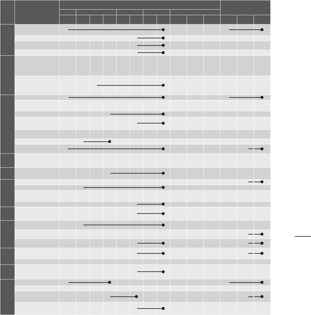
215215
Project Deliverables
Capital Project Phases
CPSD
Pre-SD SD DD CD Construction
Int. I Int. II 100% 50% 100% 75% 100%
Bid &
Award
Constr.
Admin
Post-
Constr.
Stage
I
Stage
II
Stage
III
Energy
Code
NYCECC Compliance
Path Approach
X X
EN Sheet - MEP Systems
X
EN Sheet -
Building Envelope
X
Energy Modeling Form
X
Systems and
Whole Building
Energy Performance
Energy Audit Report
X X
Energy Analysis Report
X X
Low Energy Intensity
Approach and EUI Target
X X
Energy Analysis for all
Design Alternatives
X X
Energy Model Report
X
M&V Equipment/
Monitoring Based
Commissioning Protocol
X X
On-site Renewables
Feasibility Study
X X
Net-Zero Feasibility Study
X X
LEED Project Deliverables
(see Section 4.c.vii)
X X
MOEC
Project Intake Form
X X
GHG
Greenhouse Gas
Emissions Assessment
X X
Energy
Other
Solar Assessment
X X
Sustainable Roofing Zone
X
Geothermal Pre-
Feasibility Tool
X X
Electric Vehicle Capacity
X X
Water
Water Use Reduction
X X
Site/
Stormwater
Stormwater Management
Assessment
X X
Green Infrastructure
Analysis
X X
Stormwater Pollution
Prevention Plan
X X
EPP
EPP Compliant
Specifications
X X
EPP Report
X
Active
Design
Active Design
X X
Climate Resiliency
Design Guidelines
Risks
X X
Planning
X X
Risks Summary and
Abatement
X X
Other Mitigation
Strategies
X
08
CHAPTER 08: SUSTAINABLE DESIGN
A. SUSTAINABLE DESIGN
216216
6) LEED PROJECT DELIVERABLES
For LEED projects, the Consultant shall provide the following deliverables per the schedule below
(Section 7 table). The Consultant shall update deliverables in subsequent submissions based on updated
information and DDC and Sponsor Agency comments.
All documentation shall be updated, as applicable, at the end of each phase of design, reflect the
documents submitted for that phase and be consistent with each of the project’s other LEED deliverables.
Changes to text should be bold and date of revision provided.
DDC requires an integrative design approach, which will necessitate a comprehensive approach to
integrating sustainability into the design. Consultants on all DDC projects are expected to initiate a high
level of sub-consultant coordination from the beginning of design and sustain this level of coordination
through construction. While the below checklist indicates required deliverables, it is understood that an
integrative design approach will precede these deliverables. Should any project phase be skipped, initial
deliverables shall be provided in the preceding phase, not subsequent. For projects lacking a pre-schematic
phase, the Consultant shall provide the deliverables during the first investigative sub-phase of schematic
design.
a. Environmental Design Workshop:
This goal-setting workshop to integrate high performance standards into the project shall
be organized and facilitated by the Consultant and attended by the Consultant team, DDC
representatives, and Sponsor Agency representatives, including facilities maintenance and
operations staff. For this meeting, the Consultant shall prepare for discussion preliminary drafts of
the following deliverables:
i. Environmental Programming Matrix:
Using the template provided by DDC, describe the preferred conditions of each space
including size, occupancy, hours of use, temperature, ventilation, lighting and acoustics.
The Environmental Programming Matrix shall be updated at the end of Schematic
Design and Design Development.
ii. Solar/Wind Analysis:
For new construction, additions, and substantial reconstruction, provide a site-level
sun path diagram and wind rose diagram indicating adjacent structures, and narratives
indicating how they will inform the massing, orientation, fenestration, and shading of
the project. Early “simple box” modeling of these parameters is required for Low Energy
Intensity projects and LEED projects.
iii. Energy Audit Report, as applicable:
For existing buildings, if a recent LL87-2009 energy audit and retro-commissioning
study was completed for this building, a copy of the report will be provided by DDC, if
available. The Consultant shall review the results of the audit, consider any changes
implemented in the building since the audit, and incorporate into the project those
Energy Conservation Measures (ECMs) that have the highest potential to reduce energy
consumption. If such an audit has not been conducted, DDC may direct the Consultant
to provide a whole-building ASHRAE Level II Energy Audit, including thermographic
analysis of the building envelope. The audit report shall follow the format required by
LL87 but shall address all ECMs listed in the 2017 Request for Information issued by
DCAS for “Deep Energy Retrofits in Support of EO26,” which will also be provided by
DDC.
CHAPTER 08: SUSTAINABLE DESIGN
A. SUSTAINABLE DESIGN

217217
iv. Project Specific LEED Checklist:
Provide a standard LEED checklist of targeted credits to meet local law requirements,
and a brief description of how each credit impacts the specific project.
v. Project-Specific LEED Plan:
As based on the LEED checklist, the Consultant shall provide description of each
credit’s applicability to the project, the strategy proposed to achieve targeted credits,
sub-phase to be completed, and assignment of responsibilities for the entire Project
Team. Provide explanations and calculations where appropriate for credits that are
determined to be “not feasible” for this project. The LEED Plan shall be updated at the
end of Schematic Design, Design Development, 75% Construction Documents and
100% Construction Documents. Changes to text should be bold and date of revision
provided.
vi. Site Plan Indicating LEED Project Boundary:
The LEED project boundary must include all contiguous land that is associated with
the project and supports its typical operations. This includes land altered as a result of
construction and features used primarily by the project’s occupants, such as hardscape
(parking and sidewalks), septic or stormwater treatment equipment, and landscaping.
See USGBC website for further guidance. The LEED project boundary must be
approved by OSD.
vii. Building Occupancy Group Determination:
The primary occupancy group to be used for the project building, as classified in
accordance with the New York city construction codes.
viii. Energy Goals Statement:
In addition to providing the minimum energy requirements for the project as established
by code and/or local law, the Consultant shall work with the Client’s energy manager,
capital Project Team and facilities staff to establish energy consumption and
greenhouse gas emissions goals for this project that reflect the urgency of LL66 and
EO26. For existing buildings, the goals statement shall incorporate the findings of a
previous LL87 energy audit or a new audit.
ix. Energy Analysis Plan:
Identify the energy analysis software, methodology, occupancy schedule, temperature
set points, energy rates, and other parameters to be used in the energy analysis for the
project and propose energy efficient measures and systems to be studied. Separate
analyses may be required to demonstrate compliance with LEED, local law, and code.
b. Registration
i. LEED Online Registration:
If the project is required to pursue LEED certification, the Consultant shall register the
project with GBCI and invite “ddcsustainability@ddc.nyc.gov” to the project’s LEED
Online record. For City-owned projects, register project as “City of NY – [Project Name].”
08
CHAPTER 08: SUSTAINABLE DESIGN
A. SUSTAINABLE DESIGN
218218
ii. LEED Online Submission:
The Consultant shall submit the preliminary LEED Design application to LEED Online
within 30 CCDs of the General Contractor’s notice of award. The Consultant shall
manage the review comments, collect and develop the additional project information as
needed, and submit the final LEED Design application.
c. Energy
i. HVAC Evaluation for all Design Alternatives:
The Consultant shall provide an HVAC Evaluation for all design alternatives, based on
performance, initial cost, ease and cost of maintenance, energy cost and greenhouse
gas production, space requirements, noise levels and payback periods.
ii. Energy Model Report:
The Consultant shall provide an energy model of the chosen Schematic Design scheme
that confirms the project will meet its energy efficiency target, including energy cost
reduction targets. Modeling shall be performed in accordance with local law and LEED
requirements using software in compliance with ASHRAE 140 – 2017 Standard
Method of Test for the Evaluation of Building Energy Analysis Computer Programs and
approved by the DDC Office of Sustainable Design. Additional models or variations
of one model might be necessary to meet all local laws, the energy code, and LEED
requirements.
The Consultant shall provide the findings of the model in an Energy Analysis Report.
The report shall include a comprehensive analysis of energy use, energy cost and
greenhouse gas emissions for the selected design (on a whole building and per unit
area basis), demonstrating compliance with LEED, local law and code. The analysis shall
specify recommended energy efficiency measures (EEMs) and payback periods.
The report shall be updated at the end of Design Development, 75% Construction
Documents and 100% Construction Documents, reflecting the documents submitted
for that phase. Changes to text should be bold and date of revision provided. The final
report shall be submitted with such formatting removed.
d. Environmental Construction Workshop
The Environmental Construction Workshop shall be conducted within 30 CCDs of the project’s
construction kickoff to review the construction requirements and procedures for the project and to
identify and assign responsibility for specific strategies to fulfill the targeted LEED certification level
and other City sustainability requirements. This meeting shall be organized and facilitated by the
Consultant and attended by the construction manager, Contractor, primary (MEP) sub-contractors,
Sponsor Agency representatives and DDC representatives. The meeting shall address, at a
minimum:
i. Requirements of all LEED construction credits applicable to the project
ii. Erosion and Sedimentation Control (ESC) Plan and procedures
iii. Construction and Demolition Waste Management (CDWM) Plan and procedures
iv. Indoor Air Quality Management (IAQM) Plan and procedures
CHAPTER 08: SUSTAINABLE DESIGN
A. SUSTAINABLE DESIGN

219219
v. Submittal requirements and routing, including assignment of responsibilities and
frequency of LEED construction documentation updates
vi. Construction site signage
vii. Flush-out or air quality testing requirements and scheduling
The Consultant shall review and approve the ESC, CDWM and IAQM Plans, as applicable, and
the CDWM and IAQM Plans prepared by the Contractor in advance of the Construction Kickoff
Meeting. The Consultant’s services during construction shall also include compliance review and
tracking of LEED submittal information for materials and products, collection and compilation
of all LEED construction credit information from the Contractor and construction manager. The
Consultant shall provide to DDC monthly updates on documentation of all LEED construction
credits and submit all credit documentation to GBCI within two months of substantial completion of
construction.
e. LEED Credit Deliverables
Refer to USGBC LEED Reference Guide for the project’s required measures and deliverables and
provide accordingly, except for where DDC’s required deliverables are more stringent as outlined in
section A.6.f. below.
All documentation shall be updated, as applicable, at the end of each phase of design, reflect the
documents submitted for that phase and be consistent with each of the project’s other LEED
deliverables. Changes to text should be bold and date of revision provided.
For each LEED credit deliverable, provide the applicable calculations, narratives and supporting
documents necessary to demonstrate that credit/prerequisite requirements are met. Narratives
should summarize the design approach to credit compliance and identify the project-specific design
and specifications requirements to be incorporated into the design documents. Provide explanations
and calculations where appropriate for credits that are determined to be “not feasible.”
f. Additional Deliverables for Specific Credits:
i. IP Credit: Integrative Process
1. Pre-Schematic Design:
Early in the pre-schematic design phase, the Consultant shall:
a. Conduct preliminary energy and water research and analysis, including a
“simple box” energy model.
b. Engage DDC in Integrative Process (IP) Workshop planning and agenda
development, as outlined in section A.3.j. for Sustainable Design and B.3.b. for
Resilient Design.
c. Prepare summary presentation of studies and analyses results to present at
the workshop. Send all analyses and studies included in the requirements to
DDC at least 3 days before the workshop.
d. Lead the IP Workshop, to be held separately from the Environmental Design
Workshop. Facilitate in identifying, clarifying and evaluating integrative design
opportunities. Listen to and synthesize DDC and Sponsor Agency responses
to identified challenges, opportunities and next steps.
e. Within two weeks after the IP Workshop, provide a summary of potential
strategies and follow up actions required, along with responsible parties for
each.
08
CHAPTER 08: SUSTAINABLE DESIGN
A. SUSTAINABLE DESIGN
220220
f. Complete the IP worksheet.
g. Provide an IP report that includes the following:
i. Energy and Daylight Related Systems:
Document how the energy and daylight analysis has informed the building
design, location of building on site, MEP systems and energy use. Include
the following, as applicable:
1. Established performance targets, per project’s energy
requirements by code and laws, including Energy Cost Reduction
targets and Geothermal Screening Tool results
2. Building and site program
3. Building form and site layout
4. Building envelope and façade elements on different orientations
5. Modification to, or significant downsizing of building systems
(e.g., HVAC, lighting, controls)
6. Modifications to exterior materials, interior finishes, and other
systems
7. Assessment of on-site renewable energy potential
8. An updated “simple box” energy model that evaluates energy
load reduction strategies
ii. Water Systems:
Document how the water budget analysis informed building and site design
decisions and the systems outlined below. Demonstrate how at least
one on-site non-potable water supply source was analyzed to reduce the
burden on the NYC municipal supply or wastewater treatment systems.
Include the following, as applicable:
1. Site location in a combined sewer or MS4 area, and the
applicable requirements
2. Monthly and annual rainfall volume landing on site and building
roof
3. Monthly and annual site and building water use
4. Rainwater quantity and quality management systems
5. Landscaping, irrigation, and site elements
6. Roofing systems and/or building form and geometry
7. Potential locations for green infrastructure
8. All supply sources. Assess and quantify all potential non-potable
water supply sources, such as on-site rainwater, greywater, and
HVAC equipment condensate
CHAPTER 08: SUSTAINABLE DESIGN
A. SUSTAINABLE DESIGN

221221
9. Annual Water Demand Analysis. Calculate annual water
demands for building; match with potential supply sources
10. Potential cost impact associated with installing proposed water-
conserving systems
iii. Other systems, as applicable
iv. Meeting Minutes of IP Workshop
ii. LT Cred it: High -Pr iorit y Site
Provide initial narratives and supporting documents in Pre-Schematic Design.
1. For Option 3, if brownfield remediation is part of the project’s scope of work,
provide the following deliverables:
a. Design Development: Incorporate remediation requirements into specifications
and details, and provide a narrative summarizing the actions necessary to
remediate the site and the results of these actions.
b. Construction Administration: Provide documentation from authority having
jurisdiction confirming that remediation has been completed to its satisfaction.
iii. EA Credit: Enhanced Commissioning
Refer to Section 4, Low Energy Intensity Deliverables for Monitoring-Based
Commissioning Protocol. Provide deliverables as indicated in the Section 5
Deliverables Table.
08
CHAPTER 08: SUSTAINABLE DESIGN
A. SUSTAINABLE DESIGN

222222
7) LEED PROJECT DELIVERABLES TABLE
Refer to USGBC LEED Reference Guide for the project’s required measures and deliverables and provide
accordingly, except for where DDC’s required deliverables are more stringent, as outlined in Section A.6.f.
Refer to Sections A.6.b.ii and A.6.d for timeline details on the LEED Online Submissions.
All documentation shall be updated, as applicable, at the end of each phase of design, reflect the
documents submitted for that phase and be consistent with each of the project’s other LEED deliverables.
Changes to text should be bold and date of revision provided. For each LEED credit deliverable, provide
the applicable calculations, narratives and supporting documents necessary to demonstrate that credit/
prerequisite requirements are met. Narratives should summarize the design approach to credit compliance
and identify the project-specific design and specifications requirements to be incorporated into the design
documents. Provide explanations and calculations where appropriate for credits that are determined to be
"not feasible".
KEY:
X: First submission of applicable calculations, narratives and supporting documents necessary to
demonstrate that requirements are met.
: Continue to update documents for each subsequent submission through to endpoint. Updates to
text should be identified in bold or some other means of identification. Final report shall be submitted at
100% CDs with such formatting removed.
CHAPTER 08: SUSTAINABLE DESIGN
A. SUSTAINABLE DESIGN

223223
LEED Project
Deliverables
Capital Project Phases
CPSD
Pre-
SD
SD DD CD Construction
Int. I Int. II 100% 50% 100% 75% 100%
Bid &
Award
Constr.
Admin
Post-
Constr.
Stage
I
Stage
II
Stage
III
LEED Project Kick Off
Environmental Design/
Construction Workshop
X X X
Environmental
Programing Matrix
X X
Solar/Wind Analysis
X X
Energy Audit Report,
as applicable
X X
Project-Specific
LEED Checklist
X X X
Project-Specific
LEED Plan
X X X
Site Plan Indicating
LEED Project Boundary
X X
Building Occupancy
Group Determination
X X
Energy Goals Statement
X X
Energy Analysis Plan
X X
Registration
LEED Online Registration
X
LEED Online Submission
X X
Energy
HVAC Evaluation for all
Design Alternatives
X X
Energy Model Report
X
LEED Credit Deliverables
Integrative Design
Workshop - Energy and
Water
X X
IP Credit:
Integrative Process
X X
LT Credit: Sensitive
Land Protection
X X
LT Credit: High-
Priority Site
X X X
LT Credit:
Surrounding Density
X X
LT Credit: Access to
Quality Transit
X X
LT Credit: Bicycle
Facilities
X X
LT Credit: Reduced
Parking Footprint
X X
LT Credit: Green Vehicles
X X
SS Prerequisite:
Construction Activity
Pollution Prevention
X
SS Environmental
Site Assessment
X X
SS Site Development,
Protect/Restore Habitat
X
SS Open Space
X
SS Rainwater
Management
X X
SS Heat Island Reduction
X
SS Light Pollution
Reduction
X
WE Outdoor Water
Use Reduction
X
WE Indoor Water
Use Reduction
X
WE Building-Level
Water Metering
X
WE Cooling Tower
Water Use
X
WE Water Metering
X
08
CHAPTER 08: SUSTAINABLE DESIGN
A. SUSTAINABLE DESIGN
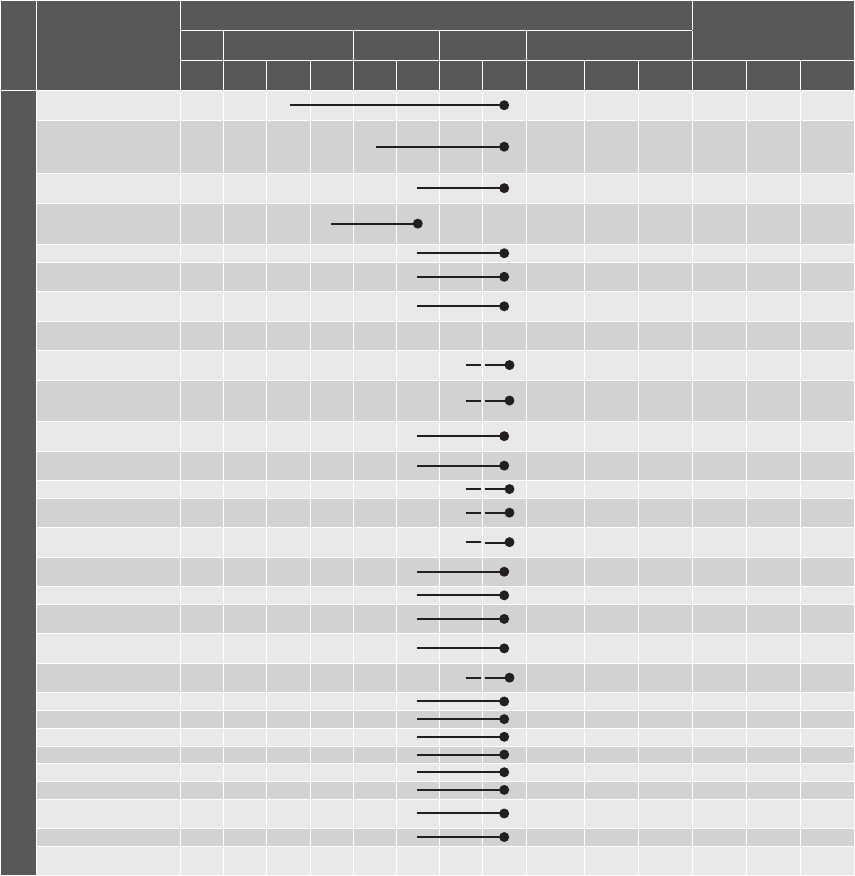
224224
LEED Project
Deliverables
Capital Project Phases
CPSD
Pre-
SD
SD DD CD Construction
Int. I Int. II 100% 50% 100% 75% 100%
Bid &
Award
Constr.
Admin
Post-
Constr.
Stage
I
Stage
II
Stage
III
LEED Credit Deliverables (cont.)
EA Minimum/ Optimize
Energy Performance
X
EA Building-Level
Energy Metering/
Advanced Energy
Metering
X
EA Fundamental
Refrigerant Management
X
EA Fundamental and
Enhanced
Commissioning
X
EA Demand Response
X
EA Renewable
Energy Production
X X
EA Enhanced Refrigerant
Management
X
EA Green Power and
Carbon Offsets
X
MR Storage and
Collection of Recyclables
X
MR Construction
and Demolition Waste
Management Planning
X
MR PBT Source
Reduction-Mercury
X
MR Building Life-Cycle
Impact Reduction
X
MR BPDO-EPDs
X
MR BPDO-Raw
Materials Sourcing
X
MR BPDO-
Material Ingredients
X
EQ Minimum Indoor Air
Quality Performance
X
EQ ETS Control
X
EQ Enhanced Air
Quality Strategies
X
EQ Low-Emitting
Materials
X
EQ Construction IAQ
Management Plan
X
EQ IAQ Assessment
X
EQ Thermal Comfort
X
EQ Inerior Lighting
X
EQ Daylight
X
EQ Quality Views
X
EQ Acoustic Performance
X
ID Innovation/ Pilot
Credits
X
ID Active Design
X
ID LEED AP with
Specialty
X
CHAPTER 08: SUSTAINABLE DESIGN
A. SUSTAINABLE DESIGN

225225
B. RESILIENT DESIGN
1) INTRODUCTION
A changing climate and rising sea levels will challenge NYC in the coming years. Resilient design, broadly
speaking, delivers projects capable of adapting to these changes. Well-coordinated tactics that can evolve
and adapt over time can create robust buildings, infrastructure, neighborhoods and services.
2) CLIMATE RESILIENCY DESIGN GUIDELINES
The City is taking a proactive stance against potential environmental threats. In March 2019, the Mayor’s
Office of Resiliency (MOR) issued the third version of their Climate Resiliency Design Guidelines (CRDG).
While these guidelines are not mandatory at present, resiliency needs to be an integral part of all new
city projects. These guidelines should serve as a starting point to incorporate resiliency into our planning
and design process as we begin to understand the risks we face. Refer to the latest version of the CRDG
available on MOR’s website.
3) DELIVERABLES
For each of the applicable deliverables listed below, refer to the Sustainable Design’s Section 5
Deliverables Table for anticipated deliverables by phase.
a. Risks
As part of the initial investigation and research phase of Schematic Design, the Consultant shall
investigate the risks that climate change poses to the project. The findings shall be on the agenda
of the Integrative Process meeting or a separate Resilient Design meeting, as appropriate.
Using the CRDG as a basis, the Consultant shall investigate the following risks:
i. Increased Heat
The CRDG address two aspects of increased heat: increasing the urban heat island
effect and the resultant increased demand on building systems.
1. Heat Island Effect
The Consultant shall design all projects to reduce their contribution to the heat
island effect as practicable. For projects pursuing LEED certification, the design
shall pursue the two Heat Island Effect credits, one for the roof and one for non-
roof. Non-LEED projects can also use these credits as a guide.
2. Building Systems and Enclosure
While the impact of increased heat on building systems will likely be significant,
the time frame in which these changes will occur exceeds the useful life of most
HVAC equipment. According to the CRDG, it is not necessary to design building
mechanical systems for these increased temperatures.
08
CHAPTER 08: SUSTAINABLE DESIGN
B. RESILIENT DESIGN
226226
On the other hand, most of our buildings will eventually experience these increased
temperatures. The useful life of the building enclosure long exceeds the time
frame in which we expect to see significant increases. Passive strategies, namely
increased insulation, window performance, and air tightness, will help mitigate the
impacts of rising temperatures and contribute to a more energy-efficient building
from the onset. These and other strategies, such as operable windows, also provide
for passive survivability when systems fail.
The Consultant shall give due attention to thermal expansion, warping, softening,
or other forms of material change, as well as accelerated degradation of structural
integrity caused by excessive heat.
The Consultant shall also investigate any alternate or emergency uses for the
facility, such as libraries being used as cooling centers. Depending on the criticality
of the facility, redundancy or back up power might be necessary.
ii. Increased Precipitation
The NYC Panel on Climate Change (NYC PCC) predicts that the City will see increased
precipitation in “normal” storms as well as more intense precipitation events.
1. Design Storm:
The CRDG lay out the process the Consultant shall use to determine increased
DEP requirements for CSOs, MS4, and direct drainage. These findings should be
incorporated into the Integrative Process meeting for water-related issues.
During schematic design, for projects with DEP retention requirements, the
Consultant shall provide a baseline design based on the current DEP requirements
and an up-sized design to meet the increased retainage suggested by the CRDG.
The Consultant shall also provide a cost estimate for this alternate.
2. Intense Precipitation Events
Although not specifically addressed in CRDG v. 3.0, the City is at risk for severe
flooding due to intense precipitation events such as the flooding in Islip, NY on
August 12-13, 2014, 13.57” of rain over 24 hours was recorded. Had this storm
tracked 40 miles to the east, portions of the city would have been devastated. In
such an event, the flow would exceed the capacity of roof drains and storm sewer
systems and the water would find its way through scuppers and the streets. In
many cases, very simple design adjustments can prevent significant flooding or
reduce the damage from flooding.
The Consultant shall investigate the risks associated with Intense Precipitation
Events that greatly exceed typical design capacities and explore the ways in
which drainage systems would fail or overflow. Attention should be paid to both
environmental risks, such as relatively low-lying sites, and building-specific risks,
such as roof overflows. The intent of this investigation is to discover potential
hazards and avoid them.
Once the results of the City’s assessment of intense precipitation events is
published, the Consultant shall incorporate those findings into their designs.
Unlike hurricanes, these events are usually sudden and unpredictable, so they do
not offer a chance to prepare barriers or other deployable structures. Management
of Intense Precipitation Events must be built into the original design.
CHAPTER 08: SUSTAINABLE DESIGN
B. RESILIENT DESIGN

227227
iii. Sea Level Rise (SLR)
The NYC PCC predicts up to 75” of SLR by 2100 in the worst-case scenario. The
middle range prediction is 22-55”, which will have severe adverse impacts on many city
facilities.
1. Tidal Inundation
The CRDG lays out the process the Consultant shall use to determine the design
flood elevation based upon expected tidal inundation due to Sea Level Rise (SLR).
Since tidal inundation will be a regular occurrence, all designs should prevent any
damage or loss of use to the facility for the expected life of the project.
The Project Objectives will present preliminary information on tidal inundation due
to SLR. The Consultant shall verify all information.
2. Storm Surge
The CRDG lay out the process the Consultant shall use to determine the design
flood elevation (DFE) for storm surge, incorporating the effects of SLR. Ideally, all
facilities will be able to handle storm surge passively, but in some cases special
designs incorporating wet or dry floodproofing might be necessary. There is usually
advanced warning of flood threat, so deployable structures may be acceptable, but
not preferred.
The Project Objectives will present preliminary information on current DFE and
future DFE based on the CRDG and the determine degrees of resilience to
explore.
The Consultant shall identify impacts, base code compliance, CRDG compliance
and professional best practices. During Schematic Design, the Consultant shall
design, present, and cost out CRDG-compliant as well as non- or partially-
compliant schemes so that the City can ascertain the benefits and costs of multiple
perspectives.
b. Planning
Following the initial schematic design investigation sub-phase, the Consultant team shall conduct
a Resilient Design meeting. Depending on the issues discovered, this may either be a dedicated
meeting or be part of a larger Integrative Process meeting.
For each of the above risks, the discussion should include:
i. Is this an issue at all? High elevations are not at risk for flooding due to SLR but may be
affected by intense precipitation.
ii. Can we avoid the issue through design? Consider raising the elevation of the building
above the design flood elevation or the surrounding area.
iii. Can we design around it? Wet or dry floodproofing, while not desirable, may be viable
options. Refer to the latest versions of the NYC Building Code and ASCE 24 Flood
Resistant Design and Construction to determine options, as based on project specifics.
iv. How? Identifying design constraints at this early stage will help set the course for a
successful project.
v. Costs associated? Many solutions can be free or have very little impact on the budget
when incorporated early.
vi. What risks cannot be avoided? Some projects must accept a certain level of risk. This
exercise will help the Sponsor Agency identify those risks.
08
CHAPTER 08: SUSTAINABLE DESIGN
B. RESILIENT DESIGN
228228
c. Risk Summary and Abatement
As Schematic Design progresses, the Consultant shall address all risks and design issues for each
option presented. At the culmination of Schematic Design, the Consultant shall present all the
required design features necessary to address climate resilience issues.
During subsequent design phases, the Consultant shall ensure that further developments and/
or modifications of the design continue to address all climate resilience issues. Systems shall be
integral with the design whenever possible.
d. Other Mitigation Strategies
In some cases, design alone will not be sufficient to assure resilience. Whenever special systems
will need to be implemented (e.g. deployment of flood barriers), or where special procedures will
be necessary (e.g. relocating vehicles or storage to higher ground), the Consultant shall prepare
a Climate Resilience Action Plan to clearly communicate to the building operators the steps
necessary to protect the asset(s) and how to train staff in their proper use. An outline of this
document shall be presented at 100% Design Development with the full document at 100%
Construction Documents. Drafts shall be presented at the 75% interim submissions for both.
Simplicity and brevity is appreciated.
CHAPTER 08: SUSTAINABLE DESIGN
B. RESILIENT DESIGN

229
CHAPTER 09:
PERCENT FOR ART
229
A. INTRODUCTION
B. THE PERCENT FOR ART LAW
C. GENERAL INFORMATION FOR THE CONSULTANT
D. APPROACHES TO COMMISSIONING PUBLIC ART
E. PERCENT FOR ART CONTRACT
F. ARTWORK REVIEW INFORMATION
G. ARTWORK PAYMENTS
H. DELIVERABLES
230230

231
CHAPTER 09: PERCENT FOR ART
A. INTRODUCTION
B. THE PERCENT FOR ART LAW
231
A. INTRODUCTION
The Percent for Art Program offers City agencies the opportunity to acquire, commission, or restore works of art
specifically for City-owned buildings throughout the five boroughs. Managed by the City’s Department of Cultural
Affairs (DCLA), the Percent for Art Program has commissioned hundreds of site-specific projects in a variety of
media — painting, new technologies, lighting, mosaic, glass, textiles, sculpture, and works that are integrated into
infrastructure and architecture — by artists whose sensibilities reflect the diversity of New York City. Percent for
Art seeks to commission works from the broadest range of artists from all backgrounds. By bringing artists into
the design process, the City’s civic buildings and public spaces are enriched. For more information and to view
examples of past Percent for Art projects visit: www.nyc.gov/percent.
As the City’s primary capital construction project manager, the Department of Design and Construction (DDC)
partners with DCLA to implement the Percent for Art program on eligible capital projects. For each eligible
capital project, an art project manager from DDC’s Public Art Unit and a representative of the Percent for Art
Program at DCLA, join the project management team for the duration of the project. Completed artworks
become a part of the collection of the City of New York.
B. THE PERCENT FOR ART LAW
Since 1982, New York City’s Percent for Art law (Local Law 65/1982) has required that one percent of the
budget for eligible City-funded construction projects be spent on public artwork. The Percent for Art law is
defined in Chapter 9 § 224 of the New York City Charter, and procedures related to the implementation of the
law are described in Title 43 § 2 of the Rules of the City of New York.
1) EXCERPTS FROM THE RULES OF THE CITY OF NEW YORK: “PERCENT FOR ART
LAW PROCEDURES”
a. Applicability
“These regulations apply to projects listed in the city’s capital budget and include each line
project and each project of a multi-project effort generally described in a lump sum budget line.
Individual projects, including multi-year projects, which are part of a major improvement program or
betterment at a specific site, may be subject to these rules as set forth below.”
b. Exemptions
“In the scope of each capital project, the Design Agency [DDC] shall specifically state, either, that:
the project is an eligible project, as defined in § 224 of the Charter; or the project is not an eligible
project.”
“The mayor may exempt a capital project from the provisions of this section if, in his/her sole
judgment, the inclusion of works of art as provided thereby would be inappropriate.”
c. Implementation
“It is the intent of the Percent for Art Law that the works of art be an integral part of and compatible
with the project being constructed. Hence, the procedures called for in these regulations are
meant to commence at the earliest stages of project design to assure that the project construction
schedule has incorporated into it the schedule to be followed for the creation, acquisition, or
restoration of the works of art to be included therein.”
09

232
CHAPTER 09: PERCENT FOR ART
C. GENERAL INFORMATION FOR THE CONSULTANT
232
2) EXCERPTS FROM THE NEW YORK CITY CHARTER: “WORKS OF ART”
a. Eligible Capital Projects
“Works of art shall be provided for each capital project which involves the construction or the
substantial reconstruction of a city-owned public building or structure the intended use of which
requires that it be accessible to the public generally or to members of the public participating in,
requiring or receiving programs, services or benefits provided thereat.”
b. Art Allocation
“An amount not less than 1% of the first $50,000,000 and 1/2% of any amount in excess of
$50,000,000 of capital funds appropriated by the city for each such capital project, other than
funds appropriated for the acquisition of real property, shall be allocated for works of art; provided,
however, that this section shall in no case require, but shall not prohibit, the expenditure of more than
$900,000 for works of art for any capital project, nor more than the sum of $4,000,000 for all works
of art in any fiscal year.”
C. GENERAL INFORMATION FOR
THE CONSULTANT
1) OVERVIEW OF KEY RESPONSIBILITIES
The Consultant shall:
a. Design any site preparation required to integrate the artwork with the design of the capital project,
including engineering and detailing or accommodating all resources necessary to support the
artwork;
b. Participate in meetings and give presentations;
c. Provide project materials and information to the Artist;
d. Make payments to the Artist for services performed;
e. Advise the Artist of all applicable statutes, ordinances, and regulations of any governmental regulatory
body having jurisdiction over the project and monitor the Artist’s compliance with said requirements;
f. Coordinate reviews of the artwork at key milestones;
g. Monitor compliance by and act as liaison to the Artist with regard to certain procedures as set forth in
the Percent for Art contract for the project.

233
CHAPTER 09: PERCENT FOR ART
D. APPROACHES TO COMMISSIONING PUBLIC ART
E. PERCENT FOR ART CONTRACT
233
D. APPROACHES TO COMMISSIONING
PUBLIC ART
The art allocation can be used in several different ways, as described below. The approach employed will be
based on the specific considerations of each project.
1) ARTIST FULL SERVICES
The Artist is responsible for designing, fabricating, and installing a site-specific artwork. The Consultant
ensures that the capital project has been designed to properly receive the artwork at installation.
2) ARTIST DESIGN ONLY
The Artist collaborates with the design team to develop an artwork that is fully integrated into the design
of the capital project. The Contractor is responsible for installing the artwork as part of the construction of
the capital project.
3) ARTWORK PURCHASE
Readily available artworks may be chosen and purchased for pre-determined locations within the capital
project. The Consultant manages transport, delivery, installation, and any other vendor services in relation
to the artworks.
4) ARTWORK CONSERVATION
Existing artwork is accessed and conserved by professionals. When appropriate, the art allocation can
be used for restoring or refurbishing existing artworks for the site, the moving of artworks to the eligible
project from another site, storage of artwork offsite while building renovation is in process, or any other
appropriate alternative recommendations. The Consultant manages the conservation project and ensures
that any necessary site preparation is completed before the installation or re-installation of the artwork.
E. PERCENT FOR ART CONTRACT
Upon selection, the Consultant shall retain and contract with the selected Artist(s). The Artist shall be responsible
for providing the artwork, as described in the Percent for Art contract. The actual contract utilized will be
determined by the specifics of a given project and the artwork approach pursued.
09

234
CHAPTER 09: PERCENT FOR ART
F. ARTWORK REVIEW INFORMATION
234
F. ARTWORK REVIEW INFORMATION
The artwork shall be reviewed and approved at key milestones, as described in the Percent for Art contract for
the project.
1) REVIEWING ENTITIES
a. Core Review Group
All artwork reviews are conducted first by the Core Review Group (CRG). The CRG includes
representatives of:
i. The Consultant
ii. The Department of Design and Construction
iii. The Department of Cultural Affairs
iv. The project Sponsor Agency
v. The facility user, if applicable
b. Community Board
Once an artwork proposal is approved by the CRG, and before Conceptual review by the Public
Design Commission, the proposal should be presented to the local community board.
c. Public Design Commission
All Percent for Art commissions must be reviewed by the Public Design Commission (PDC).
Artwork reviews should be coordinated with PDC reviews of the capital project and submitted in
tandem as shown below, whenever possible. For the installation of new artworks, PDC reviews
the project at three points: Conceptual review, Preliminary review, and Final review. For more
information, including submission checklists for each review, please refer to requirements regarding
Artwork Installation on the PDC website at www.nyc.gov/designcommission.
Capital Project Reviews New Art Work Reviews
Submit in
Tandem
Preliminary Review Conceptual Review
Final Review Preliminary Review
2) CONCEPTUAL REVIEW
Artworks should be submitted for Conceptual review and approval early in the design process and will be
reviewed at a committee meeting prior to a public hearing. If any significant design changes are made in
design development after Conceptual approval, the project must be submitted for committee review and
approval prior to proceeding to fabrication drawings.
3) PRELIMINARY REVIEW
Preliminary review and approval by the Public Design Commission shall take place when the design has
been fully developed. Approval at this stage means that a work of art can be fabricated and installed.
In addition, any conservation, restoration, repair, alteration, replication, removal, or relocation of any City-
owned artwork must be submitted to the Public Design Commission for Preliminary review and approval
before the work begins. Artworks shall not be sold, disposed of, altered, modified in any way, or relocated
without the prior written approval of the Public Design Commission.

235
CHAPTER 09: PERCENT FOR ART
G. ARTWORK PAYMENTS
235
4) FINAL REVIEW
Final review by the Public Design Commission does not occur until installation of the artwork is complete.
Final review and approval are based on the submission of color, archival-quality photographs documenting
the completed work in situ.
G. ARTWORK PAYMENTS
The Consultant is responsible for payments to the Artist. The artwork allowance will be added to the Consultant’s
scope of work through a Task Order and identified as an allowance in the Consultant’s payment requisitions.
The artwork allowance is calculated based on the capital budget for the project and is allocated as a lump sum
amount that is paid out according to the Fee Schedule in the Percent for Art contract for the project.
1) FEE SCHEDULE
A typical Fee Schedule for a Full Service Percent for Art project follows for reference. Please refer to the
actual Fee Schedule in the signed Percent for Art contract for the project for the specific terms.
Payment Milestone Percent of Total
A Initial Proposal 6%
B Conceptual Design 7%
C Preliminary Design 7%
D Notice to Fabricate 25%
E Fabrication 50% completion 25%
F Fabrication 100% completion 15%
G Installation 10%
H Final Acceptance 5%
Total 100%
2) PAYMENT PROCESS
When a payment milestone can be approved according to the requirements described in the Fee Schedule,
the following process is used to submit and process a payment to the artist:
a. The Consultant or DDC’s Public Art Unit notifies the artist and CRG of approval of the milestone.
b. The Artist submits an invoice to the Consultant for the payment milestone that has been reached,
along with any required documentation.
c. When preparing a payment requisition to DDC, the Consultant adds a corresponding percentage of
the Consultant’s fee for artwork to the amount of the artist’s invoice.
d. The Consultant includes the Artist’s invoice and any required documentation in their next payment
requisition to DDC.
e. DDC has up to 30 days for review. At any point during the review period, DDC auditors may reject
the requisition and ask the Consultant to revise and resubmit it. The 30-day review clock starts over
upon resubmission,
f. The City issues payment to the Consultant;
g. Upon receipt of funds from the City, the Consultant issues payment to the Artist as soon as possible
or within 10 business days.
09

236236
H. DELIVERABLES
1) CAPITAL PROJECT DELIVERABLES
a. Pre-Design or Schematic Design Phase
i. Initial Artwork Meeting
The Consultant is asked to participate in a brainstorm meeting to consider opportunities
for artwork and any constraints within the project scope. The Consultant may
recommend general locations and site parameters for the artwork, a concept (i.e. media,
style, materials), and/or artists to be considered. An overview of the Percent for Art
process is provided during the meeting.
ii. Workshop/Design Charrette (optional)
If requested, a charrette may be held with project stakeholders and/or potential artists
under consideration. The Consultant will prepare and present opportunities for artwork
and any related constraints within the context of the proposed project. The Consultant
will use the charrette to gather feedback about the site, initial artwork ideas, and to
assess compatibility with the Consultant’s design approach, and Sponsor Agency or
community goals and preferences. This charrette may be conducted in lieu of Artist
Selection Panel 2, depending on the project.
iii. Artist Selection Panel 1 (Managed by DCLA)
1. The Consultant will present a brief overview of the project and art opportunities
to the artist selection panel. The presentation should include project scope, site
designs, art opportunities and any related constraints, budget, schedule, and any
other considerations relevant to the panelists, Sponsor Agency, site context, and/or
local community.
2. During the panel, DCLA staff will present approximately 30 to 60 different artists
to be considered for the project. The group of artists considered may include
suggestions from: the Consultant, Project Team, panelists, community members,
and/or elected officials, among others. A DCLA staff person chairs the panel and
the voting panelists choose a small group of artists to be considered as finalists,
generally 3 to 6 artists.
3. The voting panelists include three arts professionals from the neighborhood or
borough where the project will be located and one representative each from
DCLA’s Percent for Art Program, DDC’s Public Art Unit, and the Sponsor Agency.
The Consultant and all other participants are considered advisory panelists.
An invitation to participate in the selection panel in an advisory capacity is also
extended to representatives of the Public Design Commission, local community
board, and local elected officials.
iv. Artist Orientation
1. DDC and DCLA staff will arrange a project orientation for the artist finalists. The
orientation meeting may be conducted on site, where appropriate. During the
meeting, the Consultant and Project Team will provide an overview of the project
and neighborhood context, current design, artwork budget, opportunities and
constraints for the artwork, and potential locations, if identified.
CHAPTER 09: PERCENT FOR ART
H. DELIVERABLES

237237
2. The Consultant shall distribute electronic file copies of the current design materials
to the artist finalists before or immediately following the Artist Orientation. The
materials will include: a project narrative that includes project history, mission,
vision and scope; a design description that includes site map, existing site photos,
proposed plans, and renderings or other visuals that will inform the artists about
the project, site, and opportunities; a community profile; drawings of identified art
locations and opportunities; and project sponsor information.
3. The Consultant shall also be available to respond to questions or requests for
additional information from the artists, as requested.
v. Artist Selection Panel 2 (Managed by DCLA)
1. The Consultant will present a brief overview of the project and art opportunities
to the artist selection panel. The Consultant shall participate as an advisor to the
panel.
2. Each artist is given a 30-minute time slot to present his/her proposal and/or past
work to the panel.
3. The voting panelists select an artist(s) who will be awarded the commission,
plus one or more alternates. Afterward, DCLA will notify the artist finalists of the
outcome of the panel.
vi. Percent for Art Contract
1. Upon selection, the Consultant shall retain and contract with the selected Artist(s),
using the approved Percent for Art contract for the project, as provided by the City.
2. If applicable, Payment Milestone A (Initial Proposal) is payable upon contract
signing and submission of an initial proposal for the artwork
b. Design Development Phase
i. Artist Conceptual Design Development
The Consultant will participate in meetings with the artist and/or Project Team
throughout the Conceptual Design development process.
1. The Artist’s Conceptual Design phase usually begins with a kick-off meeting with
the artist and CRG/Project Team.
2. The Consultant shall distribute electronic file copies of the current design materials
to the artist, as requested. The materials requested may include: a project narrative,
location maps, photos of the existing site and neighborhood context, existing and
proposed site plans, and drawings, renderings, or other visuals.
3. Throughout the Design Development phase, the Artist and Consultant shall work
together to integrate the artwork into the project design and the Consultant shall
advise the artist and Project Team of any applicable regulations, design parameters,
and/or potential issues.
ii. Artist Conceptual Design Review
1. Core Review Group
Upon the Artist’s submission of a completed Conceptual Design proposal, the
Consultant shall arrange for review of the Conceptual Design proposal by the CRG.
09
CHAPTER 09: PERCENT FOR ART
H. DELIVERABLES
238238
2. Community Board
Once the Artist’s Conceptual Design proposal has been approved by the CRG, and
before Public Design Commission review, the City will schedule a presentation
to the local community board for the project, if applicable. The Consultant will
attend the community board meeting to answer any relevant questions and give a
presentation if requested.
3. Public Design Commission
Following the presentation of the Artist’s Conceptual Design proposal to the
community board or, if no such presentation is made, after the Conceptual Design
is approved by the CRG, DDC, and DCLA will submit the artist’s proposal to the
Public Design Commission for Conceptual review. During the period in which the
Public Design Commission is considering the Conceptual Design proposal, the
Artist and Consultant shall be available to meet with the Project Team, Percent for
Art Program, and/or Public Design Commission to discuss the Conceptual Design
proposal and make revisions as requested. The Consultant shall accompany the
artist to the Public Design Commission hearing for the artist’s Conceptual Design
proposal, if applicable, and be prepared to answer any relevant questions.
If applicable, Payment Milestone B (Conceptual Design) is payable upon approval
by Public Design Commission of the Conceptual Design proposal for the artwork.
c. Construction Documents Phase
i. Artist Preliminary Design Development
After Public Design Commission approval of the Artist’s Conceptual Design proposal,
the Artist will prepare and submit to the Consultant a detailed Preliminary Design
proposal for the artwork. The Preliminary Design proposal should specify the materials,
dimensions, weight, finish, proposed site preparation requirements, proposed installation
method, and any additional modifications to the site necessary to prepare it for the
artwork. To assist the artist in preparing the Preliminary Design proposal, the Consultant
shall furnish to or obtain for the artist all drawings, material samples, and other similar
documentation necessary to enable the artist to prepare the Preliminary Design
proposal in compliance with any applicable legal requirements.
ii. Artwork Site Preparation/Design Integration
The Consultant is responsible for coordinating the design of the selected site with the
artwork, including engineering and detailing all resources necessary to support the
artwork and/or accommodating electrical, structural, landscaping, lighting, footings,
plumbing, and any other loads imposed by the artwork; provided, however, that all such
work shall have been fully outlined and approved in advance by the City as part of the
approved artwork design. By 75% CD review, the CDs shall note all artwork locations
on relevant drawings and all required site preparation shall be detailed, including any
drawings, dimensions, specifications, notes, and/or other information required by the
Contractor; or that are necessary for proper coordination during construction.
iii. Artist Preliminary Design Review
1. Core Review Group
Upon the Artist’s submission of a fully developed Preliminary Design proposal, the
Consultant shall arrange for review of the Preliminary Design proposal by the CRG.
CHAPTER 09: PERCENT FOR ART
H. DELIVERABLES

239239
2. Public Design Commission
Following CRG approval of the artist’s Preliminary Design proposal, DDC and DCLA
will submit the artist’s proposal to the Public Design Commission for Preliminary
review. During the period in which the Public Design Commission is considering the
Preliminary Design proposal, the artist and Consultant shall be available to meet
with the Project Team, Percent for Art Program, and/or Public Design Commission
to discuss the Preliminary Design proposal and make revisions as requested. The
Consultant shall accompany the artist to the Public Design Commission hearing for
the artist’s Preliminary Design proposal, if applicable, and be prepared to answer
any relevant questions.
If applicable, Payment Milestone C (Preliminary Design) is payable upon approval
by Public Design Commission of the Conceptual Design proposal for the artwork.
d. Construction Administration Phase
i. General Construction Coordination
The Consultant will monitor construction progress, with special attention paid to
ensuring that site preparation for the artwork is scheduled appropriately, executed
correctly, and coordinated with any relevant sub-contractors.
ii. Artwork Shop Drawings Review
The Consultant, along with the CRG, shall review all shop drawings, including materials,
means, and methods, and provide comment. The Consultant should inform the CRG
in writing of any proposed deviation from the approved Preliminary Design for the
artwork. Significant changes in the appearance, color, or dimensions of the artwork may
require submission of an amended Preliminary Design proposal to the Public Design
Commission for review. Upon approval of shop drawings for the artwork, a Notice to
Fabricate will be issued by DDC. Fabrication should not commence before a formal
Notice to Fabricate is issued.
If applicable, Payment Milestone D (Notice to Fabricate) is payable upon the artist’s
submission of approved schedule for fabrication and installation, and receipt of a Notice
to Fabricate.
iii. Artwork Inspection at 50% Fabrication
The Consultant, along with the City, will inspect the artwork at 50% fabrication
completion and provide comment. The Consultant should inform the CRG in writing
of any deviation from the approved Preliminary Design and/or shop drawings for the
artwork. Upon approval by the CRG, DDC will issue a letter documenting the approval.
If applicable, Payment Milestone E (50% Fabrication) is payable upon 50% completion
of the fabrication of the artwork, as determined by the CRG.
iv. Artwork Inspection at 100% Fabrication
The Consultant, along with the City, will inspect the artwork at 100% fabrication
completion and provide comment. The Consultant should inform the CRG in writing
of any deviation from the approved Preliminary Design and/or shop drawings for the
artwork. Upon approval by the CRG, DDC will issue a letter documenting the approval.
If applicable, Payment Milestone F (100% Fabrication) is payable upon completion of
the fabrication of the artwork and preliminary acceptance of the artwork by the CRG.
09
CHAPTER 09: PERCENT FOR ART
H. DELIVERABLES
240240
v. Artwork Installation
Once installation of the artwork is complete, the Consultant, along with the City, shall
inspect the artwork along with any related plaques or signage and provide comment.
The Consultant should inform the CRG in writing of any deviation from the approved
Preliminary Design for the artwork, or if there are outstanding construction issues that
affect or may affect the artwork. If, after artwork installation, there will be ongoing or
future construction activities that could affect the artwork, the Consultant shall ensure
that appropriate measures are being taken to protect the artwork. Upon approval by the
CRG, DDC will issue a letter documenting the approval.
If applicable, Payment Milestone G (Installation) is payable upon determination by the
CRG that the artwork as installed is ready for review and acceptance by the Public
Design Commission.
vi. Post-Installation
After installation approval and the resolution of any missing, incorrect, or incomplete
items affecting the artwork, the Artist shall submit their final deliverables to the City,
including installation photos of the artwork in situ. DDC and DCLA will then submit the
artwork installation photos to the Public Design Commission for Final Review.
vii. Artist Payment
If applicable, Payment Milestone H (Final Acceptance) is payable upon Final
Acceptance of the artwork by the Public Design Commission and completion of all other
service required of the artist under the Percent for Art contract, including submission to
Percent for Art of all required documentation.
2) CAPITAL PROJECT SCOPE DEVELOPMENT (CPSD) DELIVERABLES
a. New Artwork
The Consultant should assess the applicability of LL 65/1982 (the Percent for Art Law) to the
capital project. If the Consultant determines that Percent for Art likely applies, an anticipated
approach, budget, and possible locations or other recommendations related to the commissioning of
new artworks should be included in the Phase 3 and Final CPSD Reports.
b. Existing Artwork
If the project includes existing artwork(s), commissioned through the Percent for Art program or
otherwise, the Consultant should also assess the applicability of LL 65/1982 (the Percent for
Art Law) to the capital project regarding artwork conservation or relocation. If the Consultant
determines that Percent for Art likely applies, an anticipated approach, budget, and locations or
other recommendations related to the conservation or relocation of the existing artwork(s) should
be developed and included in the Phase 3 and Final CPSD Reports. Any measures necessary to
protect existing artwork(s) during construction should also be identified in the Final CPSD Report,
even if the artwork is not likely eligible for conservation through the Percent for Art Program.
CHAPTER 09: PERCENT FOR ART
H. DELIVERABLES

241241
CHAPTER 10:
REGULATORY
APPROVALS
A. INTRODUCTION
B. REGULATORY APPROVAL SERVICES
C. REGULATORY APPROVAL DELIVERABLES
D. DEPARTMENT OF BUILDINGS
E. NEW YORK CITY COMMUNITY BOARDS
F. PUBLIC DESIGN COMMISSION
G. LANDMARKS PRESERVATION COMMISSION
H. ADDITIONAL REGULATORY AGENCIES
242242

243243
A. INTRODUCTION
The Consultant is responsible for filing complete applications and documentation, and for obtaining all approvals
for the project in accordance with current requirements of the appropriate regulatory entities and utility
companies.
B. REGULATORY APPROVAL SERVICES
It is the professional responsibility of the Consultant to ensure that the project’s design satisfies all applicable
codes and regulations. The Consultant shall file complete applications and documentation to obtain required
approvals from the appropriate regulatory entities and utility companies. The Consultant shall include projected
dates for all required regulatory approvals and utility company applications in the overall project schedule and
update the status on a regular basis.
1) The Consultant shall file for utility service requests at the earliest possible time because review periods
can be of considerable duration. Where the same utility company provides electric, gas, and/or steam
service, requests for such services must be made at the same time. The Consultant shall include a plot
plan of the proposed building, with the desired points of service entry measured from a fixed surveyed
point. The Consultant will submit a copy of accepted service requests to the DDC Project Manager.
2) Immediately upon filing any application, the Consultant shall submit copies to the DDC Project Manager
and the Office of Community Outreach & Notification (OCON). The Consultant must follow through to
insure rapid handling and examination, to minimize time loss. The Consultant must notify the DDC Project
Manager if any delays occur. Copies of responses from regulatory agencies and utilities must be submitted
to the DDC Project Manager.
3) When approvals have been received and changes are subsequently made which affect the work, the
Consultant shall arrange to file amendments and receive approvals for the revised work. The Consultant
shall advise the DDC Project Manager and OCON of any developments which conflict with submittals
under review or submittals previously approved by regulatory agencies.
4) The Consultant shall provide documents required for permitting amendments and sign-offs.
10
CHAPTER 10: REGULATORY APPROVALS
A. INTRODUCTION
B. REGULATORY APPROVAL SERVICES

244244
C. REGULATORY APPROVAL
DELIVERABLES
1) DELIVERABLES BY PHASE
Copies of all regulatory agency approvals of both plans and applications shall be included in the required
milestone submissions.
a. Schematic Design
i. Any regulation that impacts the siting or other schematic development of the project
must be resolved prior to the conclusion of the SD phase to ensure that there are no
fatal flaws in the selected scheme. This includes zoning issues requiring a determination
(ZRD1), egress easements, or other property line issues that may impact the building’s
footprint.
ii. Public Design Commission Review. See section in this Chapter for requirements.
b. Design Development
i. Determinations by the New York City Department of Buildings (DOB)
Any item requiring clarification or pre-consideration by the DOB must be filed as a
Construction Code Determination (CCD1) and fully resolved by the conclusion of the
DD phase. Approved CCD1s are to be included with the DD Submission.
The DOB has primary responsibility for the enforcement of the NYC Building, plumbing,
mechanical, fuel and gas, electrical, energy conservation codes, the Zoning Resolution,
portions of the NYS Multiple Dwelling Law and Labor Laws, as well as the enforcement
of regulations relating to construction, alteration, maintenance, use, occupancy, safety,
and sanitary conditions of buildings in New York City. The DOB also issues violations for
non-compliance with the Building Code. Some NYC Building Code items and filings also
require approval by the DEP, DOT, FDNY, OER, or other agencies. Projects adjacent to
waterways are reviewed by the New York City Department of Small Business Services
(SBS) rather than the DOB.
ii. Hazardous Materials
When hazardous material abatement is not performed by DDC, the Consultant shall file
the appropriate documentation with DEP and DOB.
iii. Public Design Commission Review. See section in this Chapter for requirements.
iv. Landmarks Preservation Commission. See section in this Chapter for requirements.
c. 75% CD
i. Plan/Work Applications
The initial DOB Filing Set should be completed and filed with the DOB before the 75%
CD phase. Electronic filings are preferred by DDC. The Consultant shall file appropriate
applications with DOB for project work. The Consultant shall be governed by DOB
application and approval procedures as related to individual application type, such as
New Building, Alteration, Use Permits, Public Assembly, etc.. Any filings with other
Agencies having Jurisdiction must also be initiated prior to the 75% CD Phase. Filing ID
numbers shall be provided as part of the submission.
CHAPTER 10: REGULATORY APPROVALS
C. REGULATORY APPROVAL DELIVERABLES

245245
ii. Special Inspections/Progress inspections
Special/progress inspections are paid for and furnished by DDC. For each project
DDC will identify the Registered Professional responsible for the special/progress
inspections. The Consultant is responsible for identifying all items that will require
special inspections. This information should be provided to DDC four weeks prior to
the projected pre-filing date at the DOB. After the application is approved, DDC will
designate the special/progress Inspection provider who will perform the inspections.
iii. Builder’s Pavement Plan (BPP)
The Builder’s Pavement Plan Unit of the DOB and DOT reviews and approves paving
applications that are required for all new buildings and Alt 1 projects. Paving plans must
show sidewalks, street trees, curbs, roadway work, street modifications, sidewalk vaults,
drainage across sidewalks, and planned legal sidewalk, road, and curb elevations as
established by DOT or by official waiver of legally established grades.
iv. Department of Small Business Services (SBS)
The Waterfront Permits unit at SBS, instead of DOB, reviews and approves construction
on properties adjacent to the waterfront and certain other specialty projects.
v. Public Design Commission Review. See section in this Chapter for requirements.
vi. Any related existing violations which will be corrected during the process of the
application shall be included in the application process.
d. 100% CD
Any objections received by any authority having jurisdiction are to be submitted with the 100% CD
Submission.
i. B-Scan/DOB Now: Build
The Consultant shall provide copies of DOB approved plans and applications to DDC to
be held at the project construction site. The documents shall bear original DOB approval
stamp. Whenever E-filing, or DOB Now Filing, Consultant shall include DDC staff (CPM,
PM, Deputy Director and Director) as delegates.
ii. Amendments
The Consultant must file amendments for changes implemented during construction
that cause the executed work to differ from that for which approvals were originally
obtained from the regulatory agencies.
iii. Sign-offs and Certificate of Occupancy
Consultant participation may be required during the sign-off and the Certificate of
Occupancy process at the DOB. Any related existing violations corrected during the
process of the application shall be administratively closed out.
iv. Record Set
The Consultant shall also provide a digital copy of scanned, approved plans and
applications on a digital storage device for DDC’s records.
10
CHAPTER 10: REGULATORY APPROVALS
C. REGULATORY APPROVAL DELIVERABLES

246246
D. DEPARTMENT OF BUILDINGS
1) BACKGROUND AND HISTORY
a. Background
i. The Department of Buildings (DOB) promotes the safety of all people that build, work,
and live in New York City by regulating the lawful use of over one million buildings
and construction sites across the five boroughs. The Department enforces the City’s
Construction Codes, Zoning Resolution, and the New York State Multiple Dwelling Law.
ii. The Department enforces compliance with these regulations through its review and
approval of building plans, permitting and licensing functions, and inspections.
2) DEPARTMENT OF BUILDINGS REVIEW IS REQUIRED IN THE FOLLOWING
INSTANCES:
a. Building Systems Installation & Modifications
b. Alterations
c. Renovations
d. Demolition
e. Construction Equipment
f. New Buildings
3) SUBMISSION REQUIREMENTS
a. DOB Is in a process of modernizing its submission interfacing. As a result, there are currently three
approaches to submitting initial applications. They are:
i. Manual paper filing which should be avoided at all costs. Forms may be found here:
https://www1.nyc.gov/site/buildings/about/forms.page
ii. Hub Filing otherwise called E-filing or E-submit. This method is first generation of
e-filing and has 4 variants (Development Hub, Hub Full-Service, Hub Self-Service, NYC
Development Hub) https://a810-efiling.nyc.gov/eRenewal/loginER.jsp
iii. DOB Now: Build not to be confused with DOB Now: Safety, DOB Now: Inspections,
DOB Now: Licensing which is the second-generation e-filing and DDC preferred
method of filing. https://a810-dobnow.nyc.gov/publish/#/ For more, see their FAQ and
Resources sections.
1. Each of the above forms of filing has three variants for review type:
a. Plan examined (DDC preferred variant)
b. Self-Certification of objections
c. Self-Certified
CHAPTER 10: REGULATORY APPROVALS
D. DEPARTMENT OF BUILDINGS

247247
2. Closeout inspections have two variants:
a. Self-Certified usually called Directive 14
b. Agency inspection usually called Non-directive
b. Minimum DOB submission requirements for first review are:
i. Initial Application form (PW1, PA1, Laa1 or other)
ii. 3 sets of plans conforming to Bscan standards
iii. Cost affidavit (PW3)
iv. Identification of special and progress inspections (TR forms)
v. Asbestos Form or filing with DEP
c. Upon receipt of initial objections from DOB the applicant shall schedule
meetings with the plan examiner to resolve objections. Objections are usually
resolved by processing a Pre-approval amendment:
i. Submitting a PW1 to clerical staff and an AI1 form listing resolution by objection
number and meeting with the plan examiner in office or virtually
ii. Meeting with plan examiner and their supervisor (for objections not resolved in previous
step)
iii. Meeting with Chief plan examiner (for objections not resolved in previous step)
iv. Submitting a formal reconsideration process for Commissioner’s review or Technical
review
v. Getting mayoral override or affected agency waiver
4) TIMING OF SUBMISSIONS
Projects are submitted prior to 75% CD. As determined complex projects requiring DOB Zoning or
Building Code pre-determinations may also require submission earlier in the timeline. On occasion,
relatively simple projects may be filed at about 90% CD. Approval shall be attained prior to construction
kickoff meeting.
5) POST-APPROVAL AMENDMENTS
DOB has a process to amend initial approvals via the Post Approval Amendment process. This process
is basically the same as the initial approval. Changes are submitted to DOB / Changes are reviewed /
Objections are resolved via appointments and approval is obtained.
10
CHAPTER 10: REGULATORY APPROVALS
D. DEPARTMENT OF BUILDINGS

248248
E. NEW YORK CITY COMMUNITY
BOARDS
1) BACKGROUND AND HISTORY
Community boards are local representative bodies. There are 59 community boards throughout the City,
and each one consists of up to 50 unsalaried members, half of whom are nominated by their district’s City
Council members. Board members are selected and appointed by the Borough Presidents from among
active, involved people of each community and must reside, work, or have some other significant interest
in the community. Each community board is led by a District Manager who establishes an office, hires
staff, and implements procedures to improve the delivery of City services to the district. While the main
responsibility of the board office is to receive complaints from community residents, they also maintain
other duties, such as processing permits for block parties and street fairs. Many boards choose to
provide additional services and manage special projects that cater to specific community needs, including
organizing tenants associations, coordinating neighborhood cleanup programs, and more.
2) RESPONSIBILITIES & COMMITTEES
a. Responsibilities, include but are not limited to:
i. Dealing with land use and zoning issues: CBs have an important advisory role and
must be consulted on the placement of most municipal facilities in the community.
Applications for a change in or variance from the zoning resolution must come before
the board for review, and the board’s position is considered in the final determination.
ii. Assessing the needs of their own neighborhoods: CBs assess the needs of their
community members and meet with City agencies to make recommendations in the
City’s budget process.
iii. Addressing other community concerns: Any issue that affects part or all of a community,
from a traffic problem to deteriorating housing, is a proper concern of community
boards. It is important to note that while community boards serve as advocates for their
neighborhood, they do not have the ability to order any City agency or official to perform
any task. Despite this limitation, boards are usually successful in resolving the problems
they address.
b. Committees:
Board committees do most of the planning and work on the issues that are brought to action
at community board meetings. Each community board establishes the committee structure
and procedures it feels will best meet the needs of its district. Committees may be functional
committees that deal with specific Charter mandates (e.g. “Land Use Review” and “Budget”
committees) or agency committees that relate to a particular agency (e.g. “Police” and “Sanitation”
committees), among other structures. Non-board members may apply to join or work on board
committees, which helps provide additional expertise and manpower.
CHAPTER 10: REGULATORY APPROVALS
E. NEW YORK CITY COMMUNITY BOARDS

249249
3) CONSULTANT RESPONSIBILITIES
a. Community Boards have pre-set meeting dates/times/locations. This is something to keep in
mind when LPC or PDC approval is required before DOB permits may be issued. The Consultant
must anticipate the need to present to the community board and as soon as possible and with
the knowledge and assistance of DDC-Office of Community Outreach & Notification (OCON). It
is much more likely to be added to the agenda for any particular committee one or two months in
advance then it is to be added on an agenda that is only a few days or weeks away.
b. Community Boards generally do NOT have any meetings in July or August (Summer Hiatus)
c. The Consultant must prepare presentations and must attend/present as required by the needs of
the project and by DDC.
F. PUBLIC DESIGN COMMISSION
1) OVERVIEW
a. Background
The Public Design Commission (PDC) is New York City’s design review agency. PDC approval is
required for work on City-owned property as stipulated in Chapter 37 of the New York City Charter.
PDC reviews projects during design, construction, and closeout, and PDC approval is required to
obtain a building permit and a Certificate of Occupancy from the Department of Buildings (DOB).
By properly planning for PDC review, teams can ensure an efficient process that does not impact
the project schedule. All submissions and communication with PDC are managed via DDC’s PDC
liaisons, who are responsible for guiding teams through the review and approval process and
handling all PDC-related matters on behalf of the agency.
b. History
PDC was originally established as the Municipal Art Commission in 1898 to regulate public art
and architecture. Created in response to the City Beautiful movement, the Art Commission was
established as part of the City Charter that consolidated the five boroughs into a single municipality.
It was renamed the Public Design Commission in 2008 to better reflect its mission: “As an advocate
for excellence and innovation in the public realm, the PDC works to ensure the quality and viability
of public projects, programs, and services for New Yorkers in all five boroughs for years to come.”
Additional information can be found on the Commission’s website at: http://www1.nyc.gov/site/
designcommission/index.page
c. People
PDC is comprised of eleven Commissioners serving pro bono and a staff headed by an executive
director. As stipulated by the City Charter, the Commissioners include an architect, landscape
architect, painter, sculptor, and three lay members, all of whom are nominated by the Fine Arts
Federation and appointed by the mayor. They also include one representative of the Mayor’s office,
the Metropolitan Museum of Art, the New York Public Library, and the Brooklyn Museum.
10
CHAPTER 10: REGULATORY APPROVALS
F. P U B LIC DES IGN COMM IS SION
250250
d. Purview
PDC reviews permanent works of architecture, engineering, landscape, and art on City-owned
property, where “permanent” is defined as lasting for 365 days or more. PDC reviews exterior work
only, regardless of whether that work is visible, except in the case of art. PDC reviews all artworks
on City-owned property, both exterior and interior, and serves as the curator and caretaker of the
City’s public art collection.
Properties designated as NYC landmarks are subject to review by the Landmarks Preservation
Commission (LPC) instead of PDC. However, PDC has binding jurisdiction over construction of
new structures and works of landscape architecture within scenic landmarks. Additionally, PDC
has binding jurisdiction of all works of art on City owned property, including designated Landmarks.
In cases where PDC review is binding, LPC has advisory review and a written Advisory Report
from LPC must accompany the submission to PDC. See Landmarks Preservation Commission
section in this Chapter for more information, including jurisdictional purview, and to PDC’s website
for additional jurisdictional information: http://www1.nyc.gov/site/designcommission/review/
jurisdiction.page
e. Role of DDC’s PDC Liaisons
DDC’s Project Excellence team serves as the liaison to PDC, managing the submission process
and handling all PDC-related matters on behalf of the agency and its Consultants. The team
provides guidance on civic design requirements and best practices to aid projects in receiving
timely approval. DDC’s PDC liaisons advise teams on the required PDC approvals, provide up-to-
date guidance on submission requirements, and provide an in-depth review of all draft submissions
before they are submitted to PDC. All communication between project teams and PDC is handled
via the liaisons, who further assist in acquiring the requisite agency signoffs from DDC and partner
agencies. Liaisons are key stakeholders in all projects requiring PDC review and approval and
remain engaged from project kickoff through design and construction.
2) REQUIRED REVIEWS
a. Overview
PDC reviews and approves projects during design, construction, and project closeout. PDC
Commissioners meet once a month to review projects submitted by all agencies City-wide. To
be reviewed at PDC’s monthly meeting, projects must be listed on DDC’s monthly transmittal and
submitted to PDC on the required date. Before a project can be submitted to PDC, a complete
draft of the submission must be reviewed and approved by DDC’s PDC liaisons. PDC’s monthly
meeting calendar is posted on their website, and DDC’s PDC liaisons maintain and distribute a
calendar that includes draft submission deadlines.
b. Stakeholder Review and Approval
Before a project can be submitted to PDC for review and approval, it must be reviewed and
approved by all stakeholders, including the DDC Program Unit, A&E, and Project Excellence
teams, the Sponsor Agency, and any other agencies with jurisdiction over the project or site. In
addition, the community is given the opportunity to review projects prior to PDC review through the
Community Board process.
All projects subject to the Uniform Land Use Review Procedure (ULURP) must be reviewed by
PDC at a conceptual level during the application and pre-certification phase, and prior to ULURP
certification. Submission should be made at or around the same time as the Department of City
Planning (DCP) inter-divisional meeting.
See the Additional Regulatory Agencies section in this Chapter for additional information on partner
agency and Community Board requirements.
CHAPTER 10: REGULATORY APPROVALS
F. PUBLIC DESIGN COMMISSION

251251
c. Review of Capital Projects During Design
During design, the requirements for PDC review and approval depend on project type, scope, and
complexity. Large or complex projects such as new buildings, major additions or renovations, and
master plans, require at least three levels of design review. Standard projects, such as façade
replacements, ADA upgrades, and site improvements, typically require two levels of design review.
Projects with limited exterior scope, such as system upgrades, may qualify for a single level of
design review. Teams must consult with DDC’s PDC liaisons at project kickoff and throughout
design and construction to identify all required PDC reviews.
i. Conceptual Review
Conceptual review and approval occurs at Schematic Design Interim II Submission,
after selection of a schematic design scheme. It is required for all new buildings
and significant additions, major infrastructure, master plans, or other large-scale or
complex projects. As noted above, all projects subject to the Uniform Land Use Review
Procedure (ULURP) must receive PDC conceptual review prior to ULURP certification.
PDC conceptual review occurs prior to review by Community Board.
ii. Preliminary Review
Preliminary review and approval occurs at Schematic Design Final Submission. It
is required for all projects that were reviewed at a conceptual level, and for all other
projects with exterior work unless they qualify for a single design review as described
below. PDC preliminary review occurs after review by the Community Board. If the
design changes substantially after this milestone, the project must be submitted for
interim review as described below.
iii. Final Review and Combined Preliminary/Final Review
Final review and approval occurs at approximately 75% CD and is required for all
projects with exterior work, including those that were reviewed at conceptual and
preliminary levels. Projects with limited exterior scope, such as system upgrades, roof
replacements, or window replacements, may qualify for a single combined preliminary/
final review at this milestone as identified by DDC’s PDC liaisons. PDC preliminary/final
review occurs after review by the Community Board.
Final approval by PDC is required to obtain a building permit from the Department
of Buildings and must be secured before construction can proceed. If the design
changes after this milestone, the project must be submitted for amended final review as
described below.
iv. Interim Review
Interim review and approval occurs between preliminary and final review, and may be
required to address any conditions of approval stipulated by PDC at preliminary review.
Interim review is also required when the design changes substantially after preliminary
approval. DDC’s PDC liaisons guide the team in determining whether interim review is
required or appropriate.
v. Informal Review
Informal review is available for complex and high-priority projects with expedited
timelines, including projects receiving an Emergency Declaration. It occurs during a
pre-schematic or master plan phase, or during the early stages of schematic design.
Informal review does not take the place of the required design reviews but, for time-
sensitive projects, can aid in achieving Commission buy-in and support early decision-
making.
10
CHAPTER 10: REGULATORY APPROVALS
F. P U B LIC DES IGN COMM IS SION
252252
d. Review of Capital Projects During Construction
i. Amended Final Review/Construction Change
Amended final review and approval occurs when the design changes after the project
has received final approval. When this occurs during construction, amended final
review is also known as “construction change review,” and design revisions must be
submitted to PDC prior to proceeding with the work. To expedite the approval process,
construction change submissions have an abbreviated set of requirements and may be
submitted outside the typical review cycle upon coordinating with DDC’s PDC liaisons.
ii. Extension of Approval
Extension of approval occurs when the final approval expires prior to the start of
construction. Final approval by PDC is conditioned on construction commencing within
two years.
e. Review of Capital Projects During Closeout
i. Final Sign-off
Final sign-off occurs when the construction of a project is complete. It is required to
demonstrate that the project was built as approved.
Final sign-off by PDC is required to close out a building permit and obtain a Certificate
of Occupancy from the Department of Buildings.
f. Waivers for Replacement-in-Kind
For projects eligible for a PDC waiver, the waiver request occurs after a permit application has been
submitted to DOB and DOB has returned an objection identifying the requirement for PDC review.
Waivers are available for projects where the exterior work is strictly limited to repair or replacement-
in-kind, with replacement components having the same specifications, size and finish as existing
components. Replacement of exterior mechanical equipment does not typically qualify for a waiver.
DDC’s PDC liaisons will advise whether the project qualifies for a waiver.
g. Review of Artwork
Artwork is subject to separate review and approval by PDC, including the installation of new artwork
through the Percent for Art program and the conservation or relocation of existing artwork. DDC’s
PDC liaisons and Public Art team provide guidance on submission requirements and coordination
with capital project submissions.
i. Percent for Art
PDC requires Percent for Art projects to be submitted for conceptual, preliminary, and
final review. Conceptual review and approval occurs early in the design process and
should occur when the associated capital project is submitted for preliminary review.
Preliminary review and approval of Percent for Art projects occurs prior to fabrication,
and requires information on the fabricator, installation specifications, maintenance
requirements, and maintenance funding. Final review and approval occurs after
installation of the artwork and is required to demonstrate that the work was installed
as approved. As with capital projects, interim review may be required to resolve any
conditions of approval or to address substantial changes after approval. DDC’s PDC
liaisons guide the team in determining whether interim review is required or appropriate.
See Chapter 09: Percent for Art.
CHAPTER 10: REGULATORY APPROVALS
F. PUBLIC DESIGN COMMISSION

253253
ii. Artwork Relocation and Conservation
PDC requires any conservation, repair, alteration, removal, or relocation of existing City-
owned artwork to be submitted for preliminary and final review. For complex projects or
when additional guidance is needed, projects can be submitted for conceptual review
before requests for proposals (RFPs) are completed and/or before a conservation
team has been engaged. Preliminary review and approval occurs prior to the start of
work. Final review and approval occurs after the work is complete and is required to
demonstrate that the work was executed as approved.
3) SUBMISSION REQUIREMENTS
Each type of PDC review has specific submission requirements, many of which are detailed on checklists
specific to the submission (conceptual, preliminary, etc.) and project type (structures, open spaces, etc.)
DDC’s PDC liaisons provide the relevant checklists and submission instructions. For submission types that
do not have a checklist, DDC’s PDC liaisons identify the items required for the submission.
For any submissions that require an application as identified on the checklist, DDC’s PDC liaisons are
responsible for completing the application, obtaining the required agency signatures, and delivering the
original application to PDC.
4) SUBMISSION PROCESS
Successful review and approval by PDC requires that teams work closely with DDC’s PDC liaisons
throughout the project to accurately plan for all required approvals.
a. Early Planning
The team must consult with DDC’s PDC liaisons early in the design process to identify the required
PDC approvals. This early coordination ensures that the PDC review and approval process does
not impact the overall project schedule. DDC’s PDC liaisons remain key stakeholders throughout
the design and construction process and will guide the team in planning for PDC approvals in the
event of scope or design changes.
b. Pre-Submission Planning
Two to three months prior to submitting for PDC review, teams must reach out to DDC’s PDC
liaisons to obtain the current review calendar, submission checklist, and project-specific instructions
and guidelines.
c. Submission and Review of Drafts
DDC requires that a complete draft of the submission, including all items on the checklist, be
provided to DDC’s PDC liaisons by noon two weeks prior to the PDC submission date. Additional
time may be required for large or complex projects that require submission by multiple agencies.
Prior to submission of a draft, the design of the project must be approved by the DDC Program
Unit and A&E team, in addition to the Sponsor Agency and any other agencies with jurisdiction
over the site. DDC’s PDC liaisons review the draft for completeness and clarity of the submission,
conformance to PDC requirements and guidelines, alignment with city-wide standards and best
practices, and appropriateness of the design. Multiple draft revisions may be required within the
two-week period prior to PDC submission.
For certain high-priority projects, DDC may require the Consultant to present the project in person
at DDC before it is submitted to PDC. This meeting generally occurs at least one week prior to the
submission to PDC.
10
CHAPTER 10: REGULATORY APPROVALS
F. P U B LIC DES IGN COMM IS SION
254254
d. PDC Submission
PDC requires submission of hard copies, samples and models, and digital files as described
below. With the exception of the application form and Community Board letter, all items are the
responsibility of the Consultant. DDC’s PDC liaisons complete the required application form,
obtain the requisite agency signature(s), and deliver the monthly transmittal, signed application, and
Community Board letter to PDC.
i. Submission of Digital Files
DDC submits all digital files to PDC directly. A complete digital submission, including a
checklist and all indicated items, must be submitted to DDC’s PDC liaisons by noon on
the day before the PDC submission date.
ii. Submission of Hard Copies
Hard copies are delivered by the Consultant to the north entrance of 1 Centre Street
and dropped off in the mail room for screening. All materials must be clearly labeled
with the project name and addressed to the Design Commission at City Hall, Third
Floor. Hard copy submissions are due on the submission date by noon and may not be
delivered early.
iii. Submission of Samples and Models
Large or delicate samples and models may be delivered directly to PDC’s offices on the
third floor of City Hall on the submission date. Such deliveries must be coordinated in
advance with DDC’s PDC liaisons, who will arrange a delivery time with PDC staff.
After PDC has completed their review, the Consultant will be required to pick up any
models or large samples at a pre-arranged time coordinated via DDC’s PDC liaisons.
e. PDC Review
Upon submission to PDC, the project is reviewed by staff and informal committees of
Commissioners. PDC provides feedback including questions, requests for information, and requests
for revision. These requests are conveyed to the team via DDC’s PDC liaisons and require timely
response due to the limited review period.
f. PDC Meeting
Three business days prior to the monthly meeting, PDC distributes a meeting agenda via DDC’s
liaisons. The agenda includes three sections: Committee, Consent, and Public Hearing. Projects
on the Committee Agenda will be presented to PDC by the Consultant, with the DDC and Sponsor
Agency teams in attendance. Projects listed on the Consent Agenda are recommended for
approval at the meeting and do not require attendance by the team. Projects may be scheduled for
a Public Hearing if a member of the public wishes to testify.
The meeting agenda is limited to the major types of design review submission (conceptual,
preliminary, and final review, with interim review submissions occasionally presented). Other
submission types, such as construction changes, are handled via communication with DDC’s PDC
liaisons and are not included on the meeting agenda.
CHAPTER 10: REGULATORY APPROVALS
F. PUBLIC DESIGN COMMISSION

255255
i. Meeting Attendance
Meetings are typically held in PDC’s offices on the third floor of City Hall, and teams
presenting a project on the Committee Agenda are required to arrive 45 minutes in
advance of their scheduled presentation. However, meeting times and locations are
subject to change and will be confirmed by DDC’s PDC liaisons.
PDC will have the team’s submitted presentation displayed on a screen, and samples
and models will be laid out on a table. Teams may not bring any new material to the
meeting.
g. Approval and Documentation
Following the monthly meeting, PDC distributes formal communication documenting the results of
their review. The type of communication depends on the type of review. In addition, PDC meetings
are video recorded and may be viewed via a link on PDC’s website. All communication from PDC is
distributed via DDC’s PDC liaisons.
i. Interagency Communication Memo
Projects that were presented at the monthly meeting as part of the Committee Agenda
will receive an interagency communication memo summarizing feedback from the
Commission and identifying the next step. Formal approval is not granted by the
interagency communication memo, but the project may be recommended for approval at
PDC’s next meeting.
ii. Certificate and Perforated Drawing Set
Projects on the Consent Agenda will receive a numbered certificate, which serves as the
formal documentation of PDC approval. The certificate types are as follows: Conceptual
(for Percent for Art projects only), Preliminary, Final, and combined Preliminary/Final.
Preliminary certificates may include conditions of approval that must be addressed in
subsequent submissions.
Certificates for final approval include the following conditions: that construction must
commence within two years of the certificate date, and that photographs be submitted
for final sign-off upon completion of the work. For projects receiving final approval,
PDC also provides a perforated drawing set for record of the approved design.
iii. Email
PDC may require that a project be revised and resubmitted at a subsequent submission
date before it is calendared for the monthly meeting. This type of request is
communicated via email to DDC’s PDC liaisons.
For submission types not listed on the monthly meeting agenda, including construction
changes, final sign-offs, and some interim submissions, PDC’s response will be provided
by email via DDC’s PDC liaisons. This email serves as the formal documentation of
PDC’s review and approval.
10
CHAPTER 10: REGULATORY APPROVALS
F. P U B LIC DES IGN COMM IS SION

256256
G. LANDMARKS PRESERVATION
COMMISSION
1) BACKGROUND AND HISTORY
a. The Landmarks Preservation Commission (LPC) is the mayoral agency responsible for designating
and protecting New York City’s architecturally, historically, and culturally significant buildings
and sites. Since its creation in 1965 by the Landmarks Law, Section 3020 of the New York City
Charter, and Chapter 3 of Title 25 of the Administrative Code, LPC has granted landmark status
to more than 36,000 buildings, including 1,415 individual landmarks, 120 interior landmarks, 11
scenic landmarks, and 144 historic districts in all five boroughs. The agency consists of eleven
commissioners comprised of at least three architects, a historian, a realtor, and a planner or
landscape architect, as well as at least one commissioner from each borough. The paid chair leads
the agency and a staff headed by the executive director.
b. The objective of designating landmark properties is to “safeguard the city’s historic, aesthetic,
and cultural heritage” and to “foster civic pride in the beauty and accomplishments of the past.”
Protection of designated properties is achieved through mandatory review and approval of plans for
restoration, alteration, addition, reconstruction or other proposed changes.
c. The LPC has jurisdiction over all properties that are either designated or pending designation as
NYC landmarks. The four types of landmark designation are individual (exterior), interior, scenic,
and historic districts. In addition, projects undergoing City Environmental Quality Review (CEQR)
fall under LPC jurisdiction. Properties reviewed under CEQR or other environmental laws might be
listed on or eligible for the New York State or National Registers of Historic Places or meet criteria
for local designation, even if they are not New York City designated landmarks. CEQR review covers
historic, aesthetic, cultural, archaeological, and architectural resources.
d. Coordination between LPC and the Public Design Commission
Areas of overlapping jurisdiction between the LPC and the PDC have been minimized with the
adoption of Local Law 77 (1995). If the project primarily concerns an individual landmark, or a
project within an historic district, the LPC will conduct the only design review, and PDC review will
not be required. For these projects LPC review and approval will be binding. However, all projects
within scenic landmarks, except for work on existing buildings, and all works of art as defined by the
PDC will continue to require review by both the PDC and LPC.
2) DDC HISTORIC PRESERVATION OFFICE
The DDC Historic Preservation Office assists and guides the Consultant in the completion of all steps
leading to approval of the project by the Landmarks Preservation Commission and by other entities
having jurisdiction over historic properties such as the State Historic Preservation Office (SHPO). The
DDC Historic Preservation Office should be contacted at the outset of projects potentially within the
jurisdiction of the LPC to verify the designation status of the property. Assistance is provided throughout
the application and approval process, and HPO may also monitor the job during construction. The schedule
of LPC submission deadlines and hearings is available on the LPC website. Please note that “landmark
quality” properties also are identified by the DDC Historic Preservation Office. (See Historic Preservation
Design Criteria in Chapter 06: Design Criteria of this Guide for details).
CHAPTER 10: REGULATORY APPROVALS
G. LANDMARKS PRESERVATION COMMISSION

257257
3) PROCEDURES
There is usually only one formal application to the Landmarks Preservation Commission for a given project;
however, there are sometimes two or more separate submissions. The first submission accompanies the
application form for the proposed work. This is typically done during the Design Development phase when
a clear design direction has been determined. At this point a Landmarks Preservation Commission staff
member will be assigned to the project, and the likely level of action, either staff review or public hearing,
will be established.
The second required submission is for the final approval, issued in the form of a permit or report. This
submission includes final construction documents including specifications. For some simple and straight-
forward projects, a single submission near the end of design will be sufficient. When a submission for final
approval has been deemed complete by LPC staff, the Commission has 45 business days to issue a report.
For more complex projects, such as those involving a Pre-Schematic Phase or extensive alterations to a
landmark, it is important to involve the LPC early. For these projects it is useful to have a pre-submission
meeting with the LPC staff to discuss project scope and possible alternative design strategies. It is also
useful to discuss the scope of work and get advice on appropriate presentation materials. Initial contact
could be by telephone or by a meeting, depending on the nature of the project. HPO will guide the Project
Te am o n th e ap p r opr ia t e t i m ing f o r i n t era ct i o ns w ith L PC b a s ed on t he n at u r e o f t h e p r oje ct .
For projects that require a pre-submission meeting with LPC, the Consultant shall prepare all information
as required to discuss alternate strategies, schematic designs or scopes of work with the LPC staff. DDC
will receive and review the Consultant-prepared materials prior to the meeting with LPC. This meeting
should include the Sponsor Agency, the Consultant, staff of the DDC Historic Preservation Office, the
DDC project manager and team leader. After approval by DDC, the Consultant will deliver the required
submission materials to the LPC.
4) SUBMITTAL REQUIREMENTS FOR INITIAL APPLICATION
Please see the Permit Application Guide on the LPC website http://NYC.gov/landmarks for the latest
submission requirements for various types of work. These may specify materials in addition to the
general illustrative materials described below. All submission materials must be approved by DDC prior to
submitting to the LPC. Two sets are required for the LPC and two sets for DDC.
a. Application Form
The application form will be prepared by the HPO staff, with the Chief of Historic Preservation
entered as “Person Filing Application,” and the Associate Commissioner of A&E signing as “Owner.”
b. Landmark Presentation Illustrative Materials
Materials illustrating the proposed design shall include a full and complete set of drawings,
renderings, photographs, and photo-montages that clearly and completely describe all the proposed
work that affects the protected features, interior or exterior, of the landmark structure or site.
Materials will typically show, side by side, historic, existing, and proposed conditions. These typically
include all relevant floor plans, building sections, exterior elevations, interior elevations if applicable,
details, and building and site context.
10
CHAPTER 10: REGULATORY APPROVALS
G. LANDMARKS PRESERVATION COMMISSION
258258
c. Samples
One set of material and color samples with supporting product literature and identification
specifications is required.
d. Research
Relevant research, test reports, and documentation shall be submitted with the application.
e. Presentations to the Landmarks Preservation Commission Staff
Accompanied by DDC staff and the Sponsor Agency representative, the Consultant is required to
make presentations to the LPC staff.
f. Mock-Up Requirements
For all rooftop additions and/or mechanical equipment installations, the Consultant will be required
to provide all necessary information for the construction of a wood or light steel frame mock-up
matching the overall size and configuration of the proposed addition/equipment. Photographs
of the completed mock-up shall be part of the LPC submission package. In certain cases, the
mock-up may be required to remain in place for a period of time to allow Commission members
an opportunity to visit the site. Costs for the construction of the mock-up shall be identified as a
reimbursable expense or part of the construction budget, depending on the direction of the DDC
project manager.
5) SUBMITTAL REQUIREMENTS AND PROCEDURES FOR A PUBLIC HEARING
(IF REQUIRED)
Projects requiring public hearing review can be scheduled about five weeks after the Commission receives
a substantially complete application. Hearings are held on at least two Tuesdays per month, generally
during normal business hours. The scheduled time for each item on the day’s calendar is posted on the
LPC web site at the end of the week before the hearing.
If a public hearing is required for LPC review, the Consultant must first present the proposed project to
the appropriate committee of the local community board prior to the hearing. The Sponsor Agency will
typically take the lead in scheduling this with the assistance of DDC and the Consultant. Usually one
presentation to the CB committee is sufficient. However, depending on the nature of the proposed project,
the Consultant may be required to present to the full Community board as well. LPC requires that the
community board have the opportunity to review the project and submit a written resolution by the time of
the scheduled Landmarks public hearing.
It is at this stage that the Consultant must include OCON for input regarding the presentation that the
Consultant plans on showing to the Community Board. OCON may require some revisions be made
and provide the Consultant with contacts and guidance on engaging the Community Board. Once the
presentation has been executed, the Consultant will ask the Community Board to provide a “resolution”
letter which is then included as part of the submission to LPC.
Please note that most of the 59 Community Board’s Committees meet only once per month and do not
meet at all in July and August.
CHAPTER 10: REGULATORY APPROVALS
G. LANDMARKS PRESERVATION COMMISSION

259259
Illustrative materials for the public hearing are as described in section (4) above. In addition, the Consultant
must provide 12 sets of 11 by 17-inch, color copies of the presentation for distribution to the LPC
commissioners. Digital presentations in final form can be submitted by PDF or thumb-drive about one
week prior to the hearing. Presentation boards are also acceptable.
At the close of the public hearing, the Commission will vote on the project, request revisions or additional
information, or defer action. A vote, which requires a majority of the 11 commissioners, may be to approve,
approve with specified modifications, approve with revisions to be worked out with staff, or deny. A vote
(other than a denial) will result in issuance of a Status Update Letter describing the action taken. This
letter will indicate that a permit (or report) will be issued upon review of final contract documents that
conform to the Commission’s approval.
6) SUBMITTAL REQUIREMENTS FOR FINAL APPROVAL
Final Construction Documents shall include:
i. Two sets of signed and sealed drawings and one set of specifications each for LPC and
DDC.
ii. One set of material and color samples as well as related product literature and
specifications.
7) CHANGES DURING CONSTRUCTION
If there are changes to the design during construction that deviate from the approved LPC drawings, the
Consultant shall prepare for submission to LPC all necessary drawings and documentation illustrating the
changes, with a letter requesting an amendment prepared by the HPO staff.
8) NOTICE OF COMPLIANCE FROM LPC
At the end of the construction phase, LPC will issue a Notice of Compliance if so requested. The LPC
Notice of Compliance is a requirement by the Department of Buildings before its final sign-off. The
Consultant shall submit to DDC final photographs with key of all work that affected any of the protected
features of the landmark structure or site. DDC will forward these photographs to LPC with a request for
issuance of a Notice of Compliance. The Consultant shall also submit to DDC and LPC as-built drawings
for any portions of the work that deviate from the LPC-approved drawings. After determining that all the
work was completed in accordance with the approved plans and specifications as well as any amendments
to the approval, LPC will issue the Notice of Compliance.
10
CHAPTER 10: REGULATORY APPROVALS
G. LANDMARKS PRESERVATION COMMISSION

260260
H. ADDITIONAL REGULATORY
AGENCIES
Depending on circumstances, approval may also be required from other agencies. The following list is intended
as a guide and should not be considered comprehensive.
1) NYC DEPARTMENT OF CITY PLANNING (DCP) AND THE CITY PLANNING
COMMISSION (CPC)
The DCP and the CPC have overall responsibility for zoning variances, special permits, and Uniform
Land Use Review Procedure (ULURP). ULURP is required for zoning changes, site selection, acquisition
and disposition of City owned property, select concession contracts, select revocable consents, permits,
and map changes. Consultant services in support or preparation of ULURP shall be identified in the
Agreement.
2) NYC DEPARTMENT OF TRANSPORTATION (DOT)
DOT is responsible for operations relating to streets, bridges, and tunnels, and the issuance of necessary
permits. These include review and approval, as necessary, by:
a. Administrative Superintendent of Highway Operations (ASHO)
ASHO may place a hold on a permit when the proposed work location is scheduled for resurfacing
by DOT in the near future or was resurfaced within the past 18 months.
ASHO may release the hold if the proposed work can be scheduled or designed in a way that does
not interfere with planned or recent work. ASHO may also place a hold when the proposed work
location is part of a DDC street reconstruction project, in which case DDC will review the permit
and seek to coordinate the proposed work with the reconstruction
b. Bureau of Permit Management and Construction Control (the Bureau)
The Bureau issues permits relating to the maintenance and repair of public roads, streets, highways,
parkways, bridges, and tunnels. Permits are required to be taken out by the Contractor for street
closings, sidewalk and roadway construction, protective bridges (sidewalk sheds) and other similar
construction operations. The Consultant may be required to prepare necessary drawings.
c. Office of Franchises, Concessions, and Revocable Consent (OFCRC)
Approval from the OFCRC of DOT is required for any construction extending beyond the property
line, whether above or below street level, that is not exempt by provisions of the NYC Building Code,
and underground tunnels, vaults, and utilities. It is required for other work, including the construction
of bridges over streets and tunnels or utilities under roadways. Such approval can be withdrawn at
any time (revocable consent). Any above ground work, requiring revocable consent will also require
the approval of the PDC or LPC.
CHAPTER 10: REGULATORY APPROVALS
H. ADDITIONAL REGULATORY AGENCIES

261261
3) METROPOLITAN TRANSIT AUTHORITY (MTA)
If the proposed construction could infringe upon or adversely affect structures of subsurface, surface, or
elevated transit systems, it will be necessary to receive the approval of the MTA prior to receiving approval
by the DOB.
4) FIRE DEPARTMENT (FDNY)
The FDNY’s Bureau of Fire Prevention enforces all laws and rules pertaining to the prevention of fire.
5) NYC DEPARTMENT OF ENVIRONMENTAL PROTECTION (DEP)
The NYC DEP enforces all laws and rules pertaining to environmental conditions and hazardous materials
and includes:
a. Asbestos Control Program
While DEP oversees asbestos reporting and abatement in the City, DDC has primary responsibility
for identifying asbestos containing materials at DDC projects and developing drawings and
specifications for their abatement (see Section A-1 of this Appendix, Part A, “Design Process”,
and Part K, “Hazardous Materials”). In most instances, the Consultant’s responsibility is limited
to identifying potential areas of asbestos containing material and coordinating other work with
abatement work. Asbestos forms may need to be filed with DEP regardless of whether the overall
project requires filing with DOB.
b. Bureau of Environmental Planning and Analysis
The Bureau supports the City and State Environmental Quality Review processes (CEQR and
SEQR) through which City agencies may be required to assess, disclose, and plan for the
mitigation of the environmental consequences of projects (see NYS Department of Environmental
Conservation below). Consultant services in support of CEQR/SEQR, including environmental
assessment statements (EAS) and environmental impact statements (EIS), shall be identified in the
Agreement.
c. Division of Air and Noise Policy, Permitting and Enforcement
This division regulates activities and equipment that emit atmospheric contaminants, including
demolition activities that can produce airborne particulate matter, boilers that can produce noxious
gases, and construction vehicles that can produce both kinds of contaminants. This division also
enforces the NYC Noise Code, Local Law 113. The Consultant is responsible for ensuring that
noise-producing elements of the project scope, such as outdoor mechanical equipment, comply with
code.
d. Bureau of Water and Sewer Operations (BWSO)
BWSO authorizes the repair or replacement of water and sewer lines, the installation of backflow
prevention devices, and the connection of domestic water, sprinkler, sanitary, and stormwater
systems to City water and sewer mains. BWSO also provides water pressure tests for connections
to new domestic water and sprinkler systems and confirms the availability of sewer service for new
sanitary and stormwater systems. If applicable to a project, BWSO approvals are required to obtain
DOB approvals (see Appendix A-1 Section I, “Plumbing Engineering Design Criteria”).
10
CHAPTER 10: REGULATORY APPROVALS
H. ADDITIONAL REGULATORY AGENCIES
262262
e. Bureau of Wastewater Treatment (BWT)
Construction activities such as excavations and well drilling that will discharge more than 10,000
gallons per day of ground water into the public sewers must obtain a Dewatering Permit from
BWT. Projects involving well point de-watering in Brooklyn and Queens must also contact the NYS
Department of Environmental Conservation (see below).
f. NYC Water Board
The Board manages DEP’s Comprehensive Water Reuse Program, which offers a rate reduction for
buildings that capture and use stormwater.
6) NYC DEPARTMENT OF PARKS AND RECREATION (NYC PARKS)
NYC Parks approves projects within parks or designated parkland, as well as removal or planting of street
trees. Street tree plantings may be required for new construction or significant renovation projects as
required by DCP regulations. Street tree planting approval is required prior to DOB or DOT approval. Street
tree plantings must be inspected and accepted by NYC Parks Forestry division to obtain DOB final sign-off
or Certificate of Occupancy.
7) NYC DEPARTMENT OF HEALTH AND MENTAL HYGIENE (DOHMH)
The DOHMH approves the operations of food service establishments and swimming pool facilities.
DOHMH regulations also pertain to other types of facilities including day care centers and animal care
facilities.
8) NYC DEPARTMENT OF SANITATION (DSNY)
The DSNY approves refuse disposal methods, including disposal of special refuse.
9) ENVIRONMENTAL CONTROL BOARD (ECB)
The ECB is the division of the Office of Administrative Trials and Hearings (OATH) that hears cases on
violations of City laws that protect the public’s health, safety, and environment issued by agencies including,
but not limited to, the DOB, DOT, FDNY, DEP, and NYC Parks.
10) UTILITY COMPANIES AND NYS ENERGY RESEARCH AND DEVELOPMENT
AUTHORITY (NYSERDA)
Utility companies review and approve applications for electric, gas, and steam connections. Consultants
are also expected to be aware of and help Sponsor Agencies apply for energy conservation incentive
programs by NYSERDA and individual utility companies.
CHAPTER 10: REGULATORY APPROVALS
H. ADDITIONAL REGULATORY AGENCIES

263263
11) COMMUNITY BOARDS
Community Boards review and make recommendations pertaining to projects located within their
boundaries. All projects that must undertake a PDC or LPC review must begin with a presentation
reviewed by the community board and/or particular committee and/or the Full Board themselves.
Consultants may need to present new buildings, major additions, and landscape projects to at least one
group the community board designates and on occasion more than one. The Consultant should be in
direct contact with DDC/Office of Community Outreach & Notification (OCON) to begin this process. The
Consultant is also responsible for all services in support of Community Board notification and review, if
required or if requested by DDC/OCON.
12) MAYOR’S OFFICE OF ENVIRONMENTAL COORDINATION (MOEC)
This office coordinates the City Environmental Quality Review (CEQR) process. DDC projects that have
potential for significant effects on the environment, including historic resources, are subject to CEQR.
During the process these potential effects are identified and disclosed, and options for avoiding or
mitigating the effects are proposed. See the CEQR Technical Manual (https://www1.nyc.gov/site/oec/
environmental-quality-review/technical-manual.page). CEQR requirements and procedures are equivalent
to those for the New York State Environmental Quality Review (SEQR) (see section 13, below). OER has
an electronic filing process for applications at the following website: https://a002-epic.nyc.gov/app/
search/advanced
13) NEW YORK STATE AGENCIES
a. Department of Environmental Conservation (DEC)
DEC administers and enforces the State’s Environmental Conservation Law (ECL). Consultants
for DDC projects will work primarily with DEC’s office for Region 2, which covers New York City,
and with the Division of Environmental Permits, which conducts environmental assessments and
reviews projects that require DEC permits. Permit applications are processed according to the ECL’s
Uniform Procedures Act. The most common DEC reviews, permits, and authorizations required for
DDC projects include:
i. State Environmental Quality Review (SEQR)
DDC projects that receive State funding, require a DEC permit, or require discretionary
action such as a variance by a State agency, must proceed through SEQR. Under SEQR,
an Environmental Assessment Statement (EAS) must be prepared to identify potential
environmental impacts; if such impacts are anticipated, an environmental impact
statement (EIS) must be prepared to describe how they will be mitigated.
Under SEQR, projects may be designated as follows:
1. Type I Action: Projects that meet or exceed statewide or agency thresholds,
typically – but not always – requiring the preparation of an EIS.
2. Ty p e I I A c t i o n : P r o j e c t s t h a t d o n o t r e q u i r e f u r t h e r S E Q R r e v i e w .
3. Unlisted Action: Projects that do not meet Type I thresholds but may still require an
EIS.
10
CHAPTER 10: REGULATORY APPROVALS
H. ADDITIONAL REGULATORY AGENCIES
264264
ii. State Pollutant Discharge Elimination System (SPDES)
This permit is required for construction activities involving soil disturbance of at least
one (1) acre, or less than 1 acre where DEC finds a potential threat to water quality.
Construction activities involving soil disturbance of more than 5 acres at a time must
comply with additional requirements. To obtain approval, projects must prepare a
Stormwater Pollution Prevention Plan (SWPPP) that conforms to the NYS Stormwater
Management Design Manual. Because the SWPPP for a project in New York City
must be approved by DEP (see above), such projects must also conform to the DEP
Guidelines for the Design and Construction of Stormwater Management Systems.
iii. Coastal Erosion Hazard Area
This permit is required for construction activities on land along coastal waters including
the Hudson, Harlem, and East Rivers; the Kill van Kull and Arthur Kill; Long Island
Sound; the Atlantic Ocean; and all connecting water bodies, bays, harbors, shallows,
and wetlands. To obtain approval, projects must have public benefit, must not cause an
increase in erosion or have adverse effects on protective features or natural resources,
and must be safe from flood and erosion damage. DEC maintains maps of the State’s
Coastal Erosion Hazard Areas.
iv. Tidal Wetlands and Freshwater Wetlands
This permit is required for construction activities that could impact wetland functions. To
obtain approval, projects must not degrade or destroy any wetlands. DEC maintains the
State’s Fisheries (freshwater wetlands) Maps and Tidal Wetland Inventory. In general,
the City’s wetlands are concentrated around the south shores of Brooklyn and Queens
(see Critical Environmental Areas below), the north shore of Queens, the southeast
shore of the Bronx, and the north and west shores of Staten Island, with small tidal and
freshwater wetland areas scattered throughout the five boroughs, especially Staten
Island and the major parklands of northern Queens.
v. Critical Environmental Areas (CEA)
The shoreline of Jamaica Bay, which includes parts of Brooklyn and Queens, is the only
designated CEA in New York City. Projects subject to SEQR that are in or substantially
contiguous to this area must specifically evaluate potential impacts to the unique
characteristics of the CEA, which may include its benefit or threat to human health;
valuable natural, agricultural, cultural, historic, recreational, or educational qualities; or an
inherent environmental sensitivity to change.
vi. Environmental Remediation
DEC maintains the States’ Registry of Inactive Hazardous Waste Disposal Sites and,
together with the New York City Mayor’s Office of Environmental Remediation (OER),
oversees the remediation of State Superfund Sites and brownfields in the City.
b. Office of Parks, Recreation and Historic Preservation (OPRHP)
In addition to administering the seven (7) New York State parks within the City, as well as Hudson
River Park, jointly administered with the City through the Hudson River Park Trust, OPRHP
administers the State’s Open Space Conservation Plan, which identifies conservation and historic
preservation priorities on public and private property in the City and throughout the State.
CHAPTER 10: REGULATORY APPROVALS
H. ADDITIONAL REGULATORY AGENCIES

265
c. State Historic Preservation Office (SHPO):
This office of OPRHP maintains the National and New York State Registers of Historic Places
(see Landmarks Preservation Commission above) and maps of known areas of archeological
sensitivity. SHPO acts as the primary reviewer of projects receiving state or federal funding that are
found through SEQR (see DEC above) to have potential impacts on Register-listed properties or
archeological resources. Projects receiving only City funding are reviewed by LPC.
d. Department of State
Projects located in Coastal Erosion Hazard Areas (see above) must obtain a Coastal Consistency
Certification from the Department’s Coastal Management Program. The certification will be
incorporated into the permit decision of the U.S. Army Corps of Engineers if federal approval is
required, or of DEC if no federal approval is required.
10
CHAPTER 10: REGULATORY APPROVALS
H. ADDITIONAL REGULATORY AGENCIES
266
Acknowledgements
Tom Foley, PE, CCM, DBIA, NAC
Commissioner
Design Consultant Guide Team:
Eric D. Boorstyn, AIA LEED AP
Associate Commissioner Architecture & Engineering
Starling Keene, RA
Quilian Riano
Kate Solis, LEED AP
Sarah Yehuda
CHAPTER 10: REGULATORY APPROVALS
H. ADDITIONAL REGULATORY AGENCIES
267
Contributors:
DDC ARCHITECTURE & ENGINEERING:
Ashwani Bedi, PE
Dora Blount
Margaret Castillo, FAIA, LEED AP
Carol Clark
Chris Diamond, PE, LEED AP
Xenia Diente
Omar El-Anwar, PhD, PMP, CCP
Jenny Gillette, RA, LEED AP BD + C
William Harris, RLA
Frank Kugler, RA
Joseph Le Pique, RA
Rebecca Massey, CEM, CBCP, CEA
Brett Miller, PE
Mathew Park, AIA, CEM, CPCP, LEED AP BD + C
Rebecca Schmidt, LEED AP, CPHD
Sarah Shelley, CDT, LEED AP
Ron Tagliagambe, RA
Subhash Tuladhar, PMP
Isaac Vanunu, PE
Jeremy Woodoff
Raymond Zebrowski, RLA, LEED AP BD + C
PROJECT EXCELLENCE:
Michaela Metcalfe, AIA, CCM, LEED AP
Rebecca Yurek, AIA
CREATIVE SERVICES:
Michael Estabrook
Carol Hayes
Hoey-Ling Lee
CHAPTER 10: REGULATORY APPROVALS
H. ADDITIONAL REGULATORY AGENCIES

Allied Works
EMS STATION 17
FEBRUARY 18TH, 2020
PERSPECTIVE VIEW
Scale: N/A
Building Front
nyc.gov/ddc
