IPMI – A Gentle Introduction
with OpenIPMI
Montavista Software
February 10, 2006
2
Preface
This document describes IPMI in great detail; how it works and what it does and does not do. It starts
from the basics and moves into details. If you’ve heard about IPMI and want to find out more, this is the
document for you. If you know something about IPMI but wish to find out more, you can gloss over the
introductory text and dive more into the details .
This document also describes OpenIPMI and how to use that library. A basic understanding of IPMI is
required to use OpenIPMI. However, OpenIPMI hides the details of IPMI like messages and data formats;
if you do not care about those things you can skip those se c tions.
IPMI stands for Intelligent Platform Management Interface. Not a great name, but not too bad. It is
intelligent (in a manner of speaking, anyway) because it requires a processor bes ides the main processor that
is always on and maintaining the system. In most systems with IPMI, you can monitor and maintain the
system even when the main processor is turned off (though the system must generally be plugg e d in).
Platform means that IPMI deals with the platform, not the software running o n the platfor m. Software
management is mostly out of the scop e of IPMI
Management Interface means that the management system uses IPMI to talk to the s ystem to monitor
and perform maintenance on the platform. IPMI is mostly a bout monitoring, though it does have a few minor
management functions. However, many companies and organiza tions have built more extensive management
control using OEM extensions to IPMI.
The IPMI specifica tion[2], of course, has the details, but they can be obscure. This document hopefully
provides an easier to understand introduction to IPMI.
i
ii PREFACE
Contents
Preface i
Acronyms ix
1 Management, Systems, and IPMI 1
1.1 IPMI Implementation . . . . . . . . . . . . . . . . . . . . . . . . . . . . . . . . . . . . . . . . 1
1.2 System Types . . . . . . . . . . . . . . . . . . . . . . . . . . . . . . . . . . . . . . . . . . . . . 4
2 OpenIPMI 9
2.1 The User View . . . . . . . . . . . . . . . . . . . . . . . . . . . . . . . . . . . . . . . . . . . . 9
2.2 OpenIPMI Concepts . . . . . . . . . . . . . . . . . . . . . . . . . . . . . . . . . . . . . . . . . 10
2.2.1 Event-Driven Systems . . . . . . . . . . . . . . . . . . . . . . . . . . . . . . . . . . . . 10
2.2.2 The OS Handler . . . . . . . . . . . . . . . . . . . . . . . . . . . . . . . . . . . . . . . 12
2.2.3 Error Handling . . . . . . . . . . . . . . . . . . . . . . . . . . . . . . . . . . . . . . . . 14
2.2.4 Locking . . . . . . . . . . . . . . . . . . . . . . . . . . . . . . . . . . . . . . . . . . . . 14
2.2.5 OpenIPMI Objects . . . . . . . . . . . . . . . . . . . . . . . . . . . . . . . . . . . . . . 18
2.2.6 Callbacks . . . . . . . . . . . . . . . . . . . . . . . . . . . . . . . . . . . . . . . . . . . 20
2.3 OpenIPMI Include Files . . . . . . . . . . . . . . . . . . . . . . . . . . . . . . . . . . . . . . . 21
2.3.1 Files the normal user deals with . . . . . . . . . . . . . . . . . . . . . . . . . . . . . . 22
2.3.2 Files dealing with messaging interfaces . . . . . . . . . . . . . . . . . . . . . . . . . . . 22
2.3.3 File for sy stem configur ation . . . . . . . . . . . . . . . . . . . . . . . . . . . . . . . . 22
2.3.4 Semi-internal includes . . . . . . . . . . . . . . . . . . . . . . . . . . . . . . . . . . . . 22
2.4 Starting Up OpenIPMI . . . . . . . . . . . . . . . . . . . . . . . . . . . . . . . . . . . . . . . 23
2.5 Creating OpenIPMI Domains . . . . . . . . . . . . . . . . . . . . . . . . . . . . . . . . . . . . 23
2.5.1 Domain Connections . . . . . . . . . . . . . . . . . . . . . . . . . . . . . . . . . . . . . 23
2.5.2 Domain Fully Up . . . . . . . . . . . . . . . . . . . . . . . . . . . . . . . . . . . . . . . 24
2.5.3 Domain Options . . . . . . . . . . . . . . . . . . . . . . . . . . . . . . . . . . . . . . . 24
3 IPMI Interfaces 27
3.1 OpenIPMI Generic Interface . . . . . . . . . . . . . . . . . . . . . . . . . . . . . . . . . . . . . 27
3.2 System Interfaces . . . . . . . . . . . . . . . . . . . . . . . . . . . . . . . . . . . . . . . . . . . 27
3.2.1 Server Management Interface Chip (SMIC) . . . . . . . . . . . . . . . . . . . . . . . . 28
3.2.2 Keyboard Style Controller (KCS) . . . . . . . . . . . . . . . . . . . . . . . . . . . . . . 28
3.2.3 Block Transfer (BT) . . . . . . . . . . . . . . . . . . . . . . . . . . . . . . . . . . . . . 28
iii
iv CONTENTS
3.2.4 SMBus System InterFace (SSIF) . . . . . . . . . . . . . . . . . . . . . . . . . . . . . . 28
3.2.5 The OpenIPMI Driver . . . . . . . . . . . . . . . . . . . . . . . . . . . . . . . . . . . . 2 8
3.2.6 The OpenIPMI Sys tem Interface . . . . . . . . . . . . . . . . . . . . . . . . . . . . . . 34
3.3 Channels . . . . . . . . . . . . . . . . . . . . . . . . . . . . . . . . . . . . . . . . . . . . . . . 34
3.4 Bridging . . . . . . . . . . . . . . . . . . . . . . . . . . . . . . . . . . . . . . . . . . . . . . . . 35
3.4.1 Channels . . . . . . . . . . . . . . . . . . . . . . . . . . . . . . . . . . . . . . . . . . . 35
3.4.2 Sending Bridged Message . . . . . . . . . . . . . . . . . . . . . . . . . . . . . . . . . . 37
3.4.3 Message Tracking . . . . . . . . . . . . . . . . . . . . . . . . . . . . . . . . . . . . . . . 38
3.4.4 Receiving Asynchronous Messages on the System Interface . . . . . . . . . . . . . . . 38
3.4.5 System Interface to IPMB Bridging . . . . . . . . . . . . . . . . . . . . . . . . . . . . 39
3.4.6 LAN to IPMB Bridging . . . . . . . . . . . . . . . . . . . . . . . . . . . . . . . . . . . 39
3.4.7 System Interface to LAN . . . . . . . . . . . . . . . . . . . . . . . . . . . . . . . . . . 44
3.5 IPMB . . . . . . . . . . . . . . . . . . . . . . . . . . . . . . . . . . . . . . . . . . . . . . . . . 44
3.5.1 IPMB Broadcas t . . . . . . . . . . . . . . . . . . . . . . . . . . . . . . . . . . . . . . . 44
3.5.2 OpenIPMI and IPMB . . . . . . . . . . . . . . . . . . . . . . . . . . . . . . . . . . . . 45
3.6 ICMB . . . . . . . . . . . . . . . . . . . . . . . . . . . . . . . . . . . . . . . . . . . . . . . . . 45
3.7 SMBus . . . . . . . . . . . . . . . . . . . . . . . . . . . . . . . . . . . . . . . . . . . . . . . . . 45
3.8 Session Support . . . . . . . . . . . . . . . . . . . . . . . . . . . . . . . . . . . . . . . . . . . . 45
3.9 LAN . . . . . . . . . . . . . . . . . . . . . . . . . . . . . . . . . . . . . . . . . . . . . . . . . . 45
3.9.1 LAN Configuration . . . . . . . . . . . . . . . . . . . . . . . . . . . . . . . . . . . . . . 45
3.9.2 ARP control . . . . . . . . . . . . . . . . . . . . . . . . . . . . . . . . . . . . . . . . . 51
3.9.3 LAN Mes saging . . . . . . . . . . . . . . . . . . . . . . . . . . . . . . . . . . . . . . . . 51
3.9.4 OpenIPMI LAN Configuration . . . . . . . . . . . . . . . . . . . . . . . . . . . . . . . 51
3.9.5 The OpenIPMI LAN Interface . . . . . . . . . . . . . . . . . . . . . . . . . . . . . . . 52
3.10 Serial . . . . . . . . . . . . . . . . . . . . . . . . . . . . . . . . . . . . . . . . . . . . . . . . . 53
3.10.1 Serial Configur ation . . . . . . . . . . . . . . . . . . . . . . . . . . . . . . . . . . . . . 54
3.10.2 Direct Serial . . . . . . . . . . . . . . . . . . . . . . . . . . . . . . . . . . . . . . . . . 54
3.10.3 Terminal Mode . . . . . . . . . . . . . . . . . . . . . . . . . . . . . . . . . . . . . . . . 54
3.10.4 Serial over PPP . . . . . . . . . . . . . . . . . . . . . . . . . . . . . . . . . . . . . . . . 54
3.11 User Management . . . . . . . . . . . . . . . . . . . . . . . . . . . . . . . . . . . . . . . . . . 54
3.11.1 User management in OpenIPMI . . . . . . . . . . . . . . . . . . . . . . . . . . . . . . 55
3.11.2 User management commands . . . . . . . . . . . . . . . . . . . . . . . . . . . . . . . . 56
3.12 Channel Configuration . . . . . . . . . . . . . . . . . . . . . . . . . . . . . . . . . . . . . . . . 59
3.12.1 Channel handling in OpenIPMI . . . . . . . . . . . . . . . . . . . . . . . . . . . . . . . 60
3.12.2 Channel handling commands . . . . . . . . . . . . . . . . . . . . . . . . . . . . . . . . 63
3.12.3 Channel Authentication . . . . . . . . . . . . . . . . . . . . . . . . . . . . . . . . . . . 65
3.13 The PEF Table and SNMP Traps . . . . . . . . . . . . . . . . . . . . . . . . . . . . . . . . . . 65
3.13.1 PEF and Alerting Commands . . . . . . . . . . . . . . . . . . . . . . . . . . . . . . . . 65
3.13.2 The PE F Postpo ne Timer . . . . . . . . . . . . . . . . . . . . . . . . . . . . . . . . . . 67
3.13.3 PEF Configur ation Parameters . . . . . . . . . . . . . . . . . . . . . . . . . . . . . . . 67
3.13.4 OpenIPMI and SNMP Traps . . . . . . . . . . . . . . . . . . . . . . . . . . . . . . . . 76
3.13.5 The Alert Immediate Command . . . . . . . . . . . . . . . . . . . . . . . . . . . . . . 78
3.14 OpenIPMI Addressing . . . . . . . . . . . . . . . . . . . . . . . . . . . . . . . . . . . . . . . . 78
CONTENTS v
4 The MC 81
4.1 OpenIPMI and MCs . . . . . . . . . . . . . . . . . . . . . . . . . . . . . . . . . . . . . . . . . 81
4.1.1 Discovering MCs . . . . . . . . . . . . . . . . . . . . . . . . . . . . . . . . . . . . . . . 81
4.1.2 MC Active . . . . . . . . . . . . . . . . . . . . . . . . . . . . . . . . . . . . . . . . . . 82
4.1.3 MC Information . . . . . . . . . . . . . . . . . . . . . . . . . . . . . . . . . . . . . . . 82
4.1.4 MC Reset . . . . . . . . . . . . . . . . . . . . . . . . . . . . . . . . . . . . . . . . . . . 83
4.1.5 Global Event Enables . . . . . . . . . . . . . . . . . . . . . . . . . . . . . . . . . . . . 84
5 IPMI Commands 85
5.1 Sending Commands in the OpenIPMI Librar y . . . . . . . . . . . . . . . . . . . . . . . . . . . 88
6 SDR Repositories 89
6.1 SDR Reservations . . . . . . . . . . . . . . . . . . . . . . . . . . . . . . . . . . . . . . . . . . 89
6.2 The Main SDR Repository . . . . . . . . . . . . . . . . . . . . . . . . . . . . . . . . . . . . . 89
6.2.1 Modal and Non-Modal SDR Repositories . . . . . . . . . . . . . . . . . . . . . . . . . 89
6.2.2 Commands for Main SDR Repositories . . . . . . . . . . . . . . . . . . . . . . . . . . . 89
6.3 Device SDR Repositories . . . . . . . . . . . . . . . . . . . . . . . . . . . . . . . . . . . . . . . 89
6.3.1 Dynamic Device SDR Reposito ries . . . . . . . . . . . . . . . . . . . . . . . . . . . . . 90
6.3.2 Commands for Device SDR Repositories . . . . . . . . . . . . . . . . . . . . . . . . . . 90
6.4 Records in an SDR Repository . . . . . . . . . . . . . . . . . . . . . . . . . . . . . . . . . . . 90
6.5 Dealing with SDR Repositories in OpenIPMI . . . . . . . . . . . . . . . . . . . . . . . . . . . 90
6.5.1 Getting an SDR Repository . . . . . . . . . . . . . . . . . . . . . . . . . . . . . . . . . 90
6.5.2 SDR Repository Information . . . . . . . . . . . . . . . . . . . . . . . . . . . . . . . . 92
6.5.3 Handling a SDR Repository . . . . . . . . . . . . . . . . . . . . . . . . . . . . . . . . . 93
7 Entities 95
7.1 Discovering Entities . . . . . . . . . . . . . . . . . . . . . . . . . . . . . . . . . . . . . . . . . 97
7.2 Entity Containment and OpenIP MI . . . . . . . . . . . . . . . . . . . . . . . . . . . . . . . . 98
7.3 Entity Presence . . . . . . . . . . . . . . . . . . . . . . . . . . . . . . . . . . . . . . . . . . . . 99
7.3.1 Entity Presence in OpenIPMI . . . . . . . . . . . . . . . . . . . . . . . . . . . . . . . . 99
7.4 Entity Types and Info . . . . . . . . . . . . . . . . . . . . . . . . . . . . . . . . . . . . . . . . 100
7.5 Sensor and Controls in an Entity . . . . . . . . . . . . . . . . . . . . . . . . . . . . . . . . . . 102
7.6 Entity Hot-Swap . . . . . . . . . . . . . . . . . . . . . . . . . . . . . . . . . . . . . . . . . . . 105
7.6.1 Hot-Swap State . . . . . . . . . . . . . . . . . . . . . . . . . . . . . . . . . . . . . . . . 105
7.6.2 Hot-Swap Events . . . . . . . . . . . . . . . . . . . . . . . . . . . . . . . . . . . . . . . 106
7.6.3 Hot-Swap Activation and Deactivation . . . . . . . . . . . . . . . . . . . . . . . . . . . 108
7.6.4 Auto Activation and Deactivation . . . . . . . . . . . . . . . . . . . . . . . . . . . . . 109
7.7 FRU Data . . . . . . . . . . . . . . . . . . . . . . . . . . . . . . . . . . . . . . . . . . . . . . . 109
7.7.1 Reading FRU Data . . . . . . . . . . . . . . . . . . . . . . . . . . . . . . . . . . . . . . 109
7.8 Entity SDRs . . . . . . . . . . . . . . . . . . . . . . . . . . . . . . . . . . . . . . . . . . . . . 114
8 Sensors 115
8.1 Sensor Events . . . . . . . . . . . . . . . . . . . . . . . . . . . . . . . . . . . . . . . . . . . . . 115
8.2 Rearm . . . . . . . . . . . . . . . . . . . . . . . . . . . . . . . . . . . . . . . . . . . . . . . . . 115
8.3 Threshold Sensors . . . . . . . . . . . . . . . . . . . . . . . . . . . . . . . . . . . . . . . . . . 115
8.3.1 Threshold Sensor Events . . . . . . . . . . . . . . . . . . . . . . . . . . . . . . . . . . . 116
vi CONTENTS
8.3.2 Hysteresis . . . . . . . . . . . . . . . . . . . . . . . . . . . . . . . . . . . . . . . . . . . 116
8.4 Discrete Sensors . . . . . . . . . . . . . . . . . . . . . . . . . . . . . . . . . . . . . . . . . . . 118
8.5 IPMI Commands Dealing with Sensor s . . . . . . . . . . . . . . . . . . . . . . . . . . . . . . . 118
8.6 Using Sensors in OpenIP MI . . . . . . . . . . . . . . . . . . . . . . . . . . . . . . . . . . . . . 118
8.6.1 General Information About Sensors in OpenIPMI . . . . . . . . . . . . . . . . . . . . . 127
8.6.2 Threshold Sensors in OpenIPMI . . . . . . . . . . . . . . . . . . . . . . . . . . . . . . 133
8.6.3 Discrete Sensors in OpenIPMI . . . . . . . . . . . . . . . . . . . . . . . . . . . . . . . 142
8.7 Sensor SDRs . . . . . . . . . . . . . . . . . . . . . . . . . . . . . . . . . . . . . . . . . . . . . 143
9 Controls and Miscellany 145
9.1 Controls . . . . . . . . . . . . . . . . . . . . . . . . . . . . . . . . . . . . . . . . . . . . . . . . 145
9.1.1 Control Name . . . . . . . . . . . . . . . . . . . . . . . . . . . . . . . . . . . . . . . . . 14 6
9.1.2 Controls and Events . . . . . . . . . . . . . . . . . . . . . . . . . . . . . . . . . . . . . 147
9.1.3 Basic Type Controls . . . . . . . . . . . . . . . . . . . . . . . . . . . . . . . . . . . . . 147
9.1.4 Light . . . . . . . . . . . . . . . . . . . . . . . . . . . . . . . . . . . . . . . . . . . . . . 1 48
9.1.5 Display . . . . . . . . . . . . . . . . . . . . . . . . . . . . . . . . . . . . . . . . . . . . 151
9.1.6 Identifier . . . . . . . . . . . . . . . . . . . . . . . . . . . . . . . . . . . . . . . . . . . 151
9.1.7 Chassis Controls . . . . . . . . . . . . . . . . . . . . . . . . . . . . . . . . . . . . . . . 151
9.2 Watchdog Timer . . . . . . . . . . . . . . . . . . . . . . . . . . . . . . . . . . . . . . . . . . . 151
9.3 Direct I
2
C Access . . . . . . . . . . . . . . . . . . . . . . . . . . . . . . . . . . . . . . . . . . . 152
10 Events 153
10.1 Event Format . . . . . . . . . . . . . . . . . . . . . . . . . . . . . . . . . . . . . . . . . . . . . 153
10.2 Event Data Information for Specific Events . . . . . . . . . . . . . . . . . . . . . . . . . . . . 153
10.3 MC Event Enables . . . . . . . . . . . . . . . . . . . . . . . . . . . . . . . . . . . . . . . . . . 154
10.4 Coordinating Multiple Users of an SEL . . . . . . . . . . . . . . . . . . . . . . . . . . . . . . 154
11 Other OpenIPMI Concerns 155
11.1 When Operations Happen . . . . . . . . . . . . . . . . . . . . . . . . . . . . . . . . . . . . . . 155
A Special IPMI Formats 157
A.1 IPMI strings . . . . . . . . . . . . . . . . . . . . . . . . . . . . . . . . . . . . . . . . . . . . . 157
A.1.1 Ope nIPMI and IPMI strings . . . . . . . . . . . . . . . . . . . . . . . . . . . . . . . . 157
B The Perl Interface 159
C Compariso n wi th SNMP 163
D Comparison w ith HPI 165
E ATCA 167
F Motorola MXP 169
G Intel Se rvers 171
H Sample Program Showing Basic Operations 173

CONTENTS vii
I Sample Program Showing Event Setup 185
J Command Receiver Program 201
K Connection Handling Interface (ipmi
conn.h) 205
L OS Handler Interface (os
handler.h) 217
viii CONTENTS
Acronyms
ATCA AdvancedTCA
IPMI Intellige nt Platform Mangement Interface
OEM Original Equipment Manufacturer
SDR Sensor Device Record
FRU Field Replacable Unit
KCS Keyboard Style Controller
BT Block Transfer
SMIC Serve r Management Interface Chip
SSIF SMBus System InterFace
MC Management Controller
BMC Baseboard Mana gement Controller
I
2
C Inter Integrated Circuit
SNMP Simple Network Management Protocol
SPD Serial Presence Detect
HPI Hardware Platform Interface
LUN Logical Unit Number
NetFN Network FuNction
IPMB Intelligent Platform Management Bus
EEPROM Electronically Erasable Programmable Read Only Memory
LAN Local Area Network
SEL System Event Log
ix
x ACRONYMS
PPP Point to Point Protocol
RMCP Remote Mana gement Control Protocol
IP Internet Protocol
UDP User Datagram Protocol
MD2 Message Digest 2
MD5 Message Digest 5
PDU Protocol Data Unit In SNMP, this is a packet holding an SNMP operation.
PEF Platform Event Filter
MAC Media Access Code?
ARP Address Resolution Protocol
GUID Globally Unique IDentifier
NMI Non Maskable Interrupt
EAR Entity Associa tion Recor d
DREAR Device Relative Entity Association Record
DLR Device Locator Record
MCDLR Management Controller Device Locator Record
FRUDLR Field Replacable Unit Device Locator Record
GDLR Generic Device Locator Record
ICMB Intelligent Chassis Management Bus
PET Platform Event Trap
DMI ?
Chapter 1
Management, Systems, and I P MI
Management will mean different things to differe nt industries. In simple server systems, a manag e ment
system may only deal with controlling power on a few servers and making sure they don’t get too hot. In a
telecom system, management systems generally control every aspect of the system, including star tup of all
parts of the system, full monitoring of all co mpo nents of the system, detection and recovery from software
and hardware errors, basic configuration of the system, and a host of other things. IPMI obviously only
plays one role in this, but it is a role that must be played. In the past, the monitoring and management of
hardware has been done with lots of proprietary interfaces. IPMI standardizes this interface.
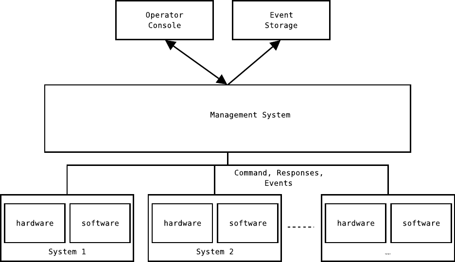
Figure 1.1 shows a management system and the things it manages. IPMI fits mostly within the “Hard-
ware” box, although there may be other hardware interfaces the management system must manage. The
management system ties into all elements of the system and makes global decisions based upon inputs from
all parts of the systems. For instance, a server may b e overheating or have a low voltage. The management
system will be informed of this through the hardware interfaces. It may choose to move the function of that
server to another server and bring that server down so it may be repaired. If no other server is available to
take over the oper ation, the management system may look at the s e verity of the problem, predict how long
the s ystem may survive, and let it co ntinue. These types of decisions are called “policy”.
In all cases these events are logged to permanent storage. An operator is informed of things that need
human attention. The opera tor may also issue manual operations to configure and override the management
system as necessary.
The operations the management system performs on the system are called “Commands” in this picture.
Commands have “Responses” from the system. Asynchronous notifications from the system to the manage-
ment system are called “Events”. The sys tem never sends commands to the management system, and the
system may perform local operations on its own (such as controlling fan speed) but never per form global
operations unless pre-configured by the management sys tem to do so. So the system may perform limited
policy decisions, but the management system is firmly in control of policy.
1.1 IPMI Implementation
The Management Controller (MC) sits at the center of an IPMI s ystem, providing the “intelligence” of IPMI.
It is suppose to be always on when the system is plugged in, even if the system is off. The management
system communicates with the management controller; the management controller provides a normalized
1
2 CHAPTER 1. MANAGEMENT, SYSTEMS, AND IPMI
Figure 1.1: Management Interfac e s
1.1. IPMI IMPLEMENTATION 3
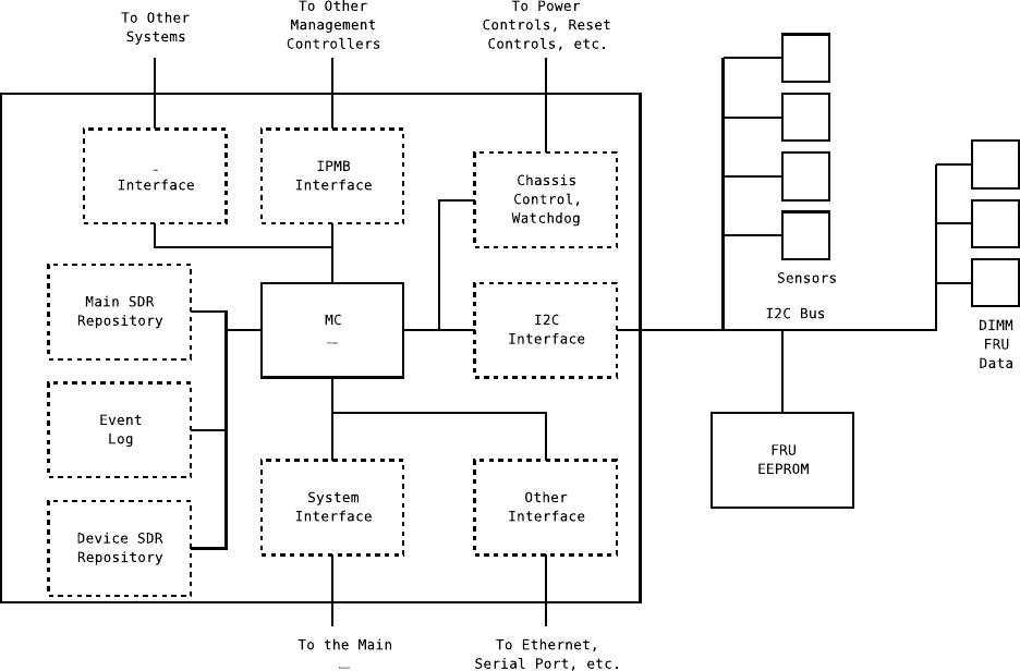
Figure 1.2: Parts of a Mana gement Controller
interface to all the sensors, events, and Field Replacable Unit (FRU) data in the system.
Figure 1.2 shows the va rious parts of the management controller. Note that most everything is optional;
depending on what a management contro ller does it may only need some things. The Baseb oard Management
Controller (BMC) is required to have a lot of the items.
The MC Processor is generally a small, inexpensive, but reliable microcontroller. Several companies sell
processors that have a lot of the IPMI components a lready implemented and software to help a company
implement IPMI on their system.
The system interface provides a way for the main pro c e ssor to communicate with the management
controller. Some systems do not have this connection a nd only use external interfaces and/or Intelligent
Platform Management Bus (IPMB) interfaces. System interfaces include SMIC, KCS, and BT interfaces.
An MC (generally the BMC) may have other interfaces to an external ma nagement system through serial
ports or Ethernet.
Generally, sensors sit on an I
2
C bus since many off-the-s helf sensors can sit directly on the bus with
no extra logic. Wherever the sensors sit, the MC provides a more abstract interface to the sensors so that
the management system does not have to know the details of how to talk to the sensor. Sensors may be
traditional analog sensors like temp e rature and voltage. But they may report other things, too, like the
4 CHAPTER 1. MANAGEMENT, SYSTEMS, AND IPMI
current BIOS state, whether a device is present or not, or other things like that.
FRU data is often stored in I
2
C EEPROMs on the I
2
C bus. FRU da ta is information about a Field
Replacable Unit. This includes things like the manufacturer, the serial number, date of manufacture, etc. A
system generally has information about the chassis and information about each field replaceable unit it has.
Field replaceable units may include power supplies, DIMMs (memory devices ), plug-in-boar ds , or a host of
other things.
Connections to other MCs may be done through a n IPMB . On an IPMB, each MC is a peer and they
communicate dir ectly through messages.
In addition to IPMB, IPMI systems can be interconnected through an Intelligent Chassis Manag e ment
Bus. This is a serial bus that runs between chassis.
A manage ment controller may be able to control various aspects o f the chassis, such as power and reset.
It may also have a watchdog timer for the main processor.
The Sensor Device Record (SDR) repositories store information about the sensors and components of
the system. The BMC must have a main SDR repository; this repository is writable. There may only be
one main SDR repository in the sys tem. Any MC may have a device SDR repository; these are a re ad-only
repositories.
When a problem or change in the system is detected, the MC handling tha t sensor may issue an event.
This allows management software to detect these problems or changes without having to poll every sensor
constantly. The events are stored in an event log. Events may be for warded through the system inter face or
other interfaces, but they are always stored in the event log. The BMC must have an event log; generally
the other management controllers forward their events to the BMC.
1.2 System Types
Although any arbitrary type of s ystem may use IPMI for platform management, systems generally fall into
two categories: server systems and bus systems.
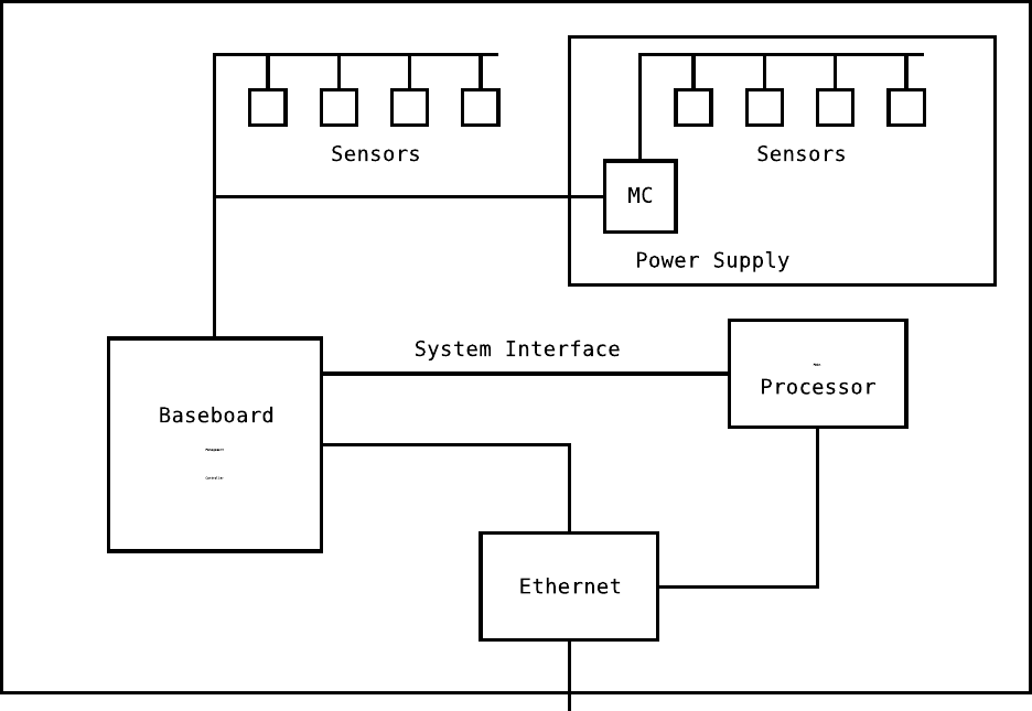
Figure 1.3 shows a typical server system. It is a single stand-alone box that is a single computer. It
has a BMC that is the main management controller in the system. It controls a number of sensors. In this
example, the power supply also has a MC with it’s own sensor s.
A BMC can have several connectio ns to managing systems. It may have a system interface connection to
the main process or. It may share an interface to the ethernet chip so the system may be managed through
the LAN when the main process or is not working. Systems can have serial po rt connections. They can even
have connections to modems where they can dial up a management system or page an operator w hen they
detect a problem, or be dialed into by a management system.
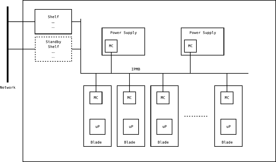
Figure 1.4 shows a typical bus s ystem. The word “bus” is perhaps a bit misleading ; these types of
systems used to have busses (like CPCI and VME) but re c e ntly have tended to not have big busses and use
networking for interconnect (like PICMG 2.16 and ATCA). These systems generally contain a number of
processors on pluggable boards often called Single Board Computers (SBCs) or blades. One or mor e powe r
supplies power the whole system. The boards and power supplies can be hot-plugg able.
These systems generally have one or two boards that manage the system; this can be on a standard SBC,
on another special purpose blade (like a blade used as a network switch), o r on a standalone bo ard with this
purp ose. The shelf management controller(s) generally act as the BMC in the system; they will have the
event log and the main SDRs in the system. A system with two shelf controllers will generally allow the
system to be managed even if one of the shelf controllers fails.
1.2. SYSTEM TYPES 5
Figure 1.3: A typical ser ver system
6 CHAPTER 1. MANAGEMENT, SYSTEMS, AND IPMI
Figure 1.4: A typical bus system
1.2. SYSTEM TYPES 7
Bus systems generally use one or more IPMBs (a sister standard to IPMI) to interconnect the various
components for management. IPMB is a modified I
2
C interface; it provides for a somewhat slow but simple
communication bus.
The boards can generally be individually power controlled, so even though a board is plugged into the
system it may be turned off. The shelf ma nagment controller may implement some policy, such as fan
controls or auto-powering up boa rds, but is generally used as a conduit for an external management system
to control the par ts of the s ystem.
Individal SBCs vary on whether the local Management Controller is connected to the microprocessor on
an SBC. Some are, and some ar en’t. This connection has some limited usefulness if the software on the SBC
wishes to obtain local information from the IPMI system or store logs in the IPMI event log.
These types o f systems ar e used to achieve high density in places with expensive real-estate, like a telco
central office. As you might imagine, you can pack a lot of processing power into a small space with a system
like this. Since they are generally designed for hot-swap, and can have I/O come out the back of the system
on separate car ds ; it makes mainenance easier.
8 CHAPTER 1. MANAGEMENT, SYSTEMS, AND IPMI
Chapter 2
OpenI P MI
So now we’ve got a BMC, MCs, and things like that. But how are you expected to use raw IPMI?
The first things you must do, of course, is connect to the BMC. If it’s a direct SMI connection (A SMIC,
KCS, or BT interface, or perhaps a non-standard serial interface), you just open the driver on the o perating
system and start messaging. If it’s a LAN-type connection, you have to go through an authentication
sequence. One you have a connection to the BMC, things are pretty much the same no matter what
interface you have. There are a few mes saging for doing sp e c ial controls on a LAN interface, but they don’t
generally matter to the user.
Once the connection to the BMC is up, the user should query to see wha t channels the BMC supports.
For 1.5 and later, it gets this from a command. For 1.0, it gets it from the ma in SDR repository.
Once you are connected, you should scan the SDRs in the main SDR rep ository for any entities and
sensors. Sensors and entities may a lso be in the device SDR repositor y, which should be scanned next. This
allows the user to discover the se nsors in the system. Note that the sensor s may point to entities that don’t
have a entry in the SDR that defines them, those entities need to be handled when they are detected.
After this point in time, the interface could be deemed to be “up”. However, there’s still more to do.
If the interface supports an event queue, the user will have to poll it (if the driver doesn’t deliver them
asynchronously, that is). If the interface doesn’t support a n event queue the user should pe riodically scan
the system event log for new events. (Note that even if it does support an event queue, the user should s till
poll the s ystem event log in case the event queue missed any events coming in.)
Also, the user should start scanning the IPMB bus with broadcast get device id commands to detect any
MCs on the bus.
This is what the OpenIPMI library does for you. Beyond this, it also represents the sensors, controls,
and entities in a nice OO fashion, and it handles the details of addressing, message routing, and other things
you don’t really care about. It lets you get right at the sensors and entities.
2.1 The User View
A bunch of acronyms have just been introduced, alo ng with a lot of vague concepts, and so me description
about how to use IPMI. The nice thing is that the user of OpenIPMI doesn’t re ally have to know about all
these things.
9
10 CHAPTER 2. OPENIPMI
From the user’s point of view, the entity provides the c e ntral framework for sensors and controls. Sensors
monitor entities. Entities may be present or absent. When you connect to an interface, OpenIPMI takes care
of detecting the entities in the sys tem and reporting them to you. You may register to be told w hen e ntities
are added or removed from the local databas e . Note that an entity may be in the SDRs but not physically
present in the system; the r e porting from only gives the existance in the SDRs, not physical presence in the
system. Physical presence it handled through a separate interface.
The user must know about two other Op e nIPMI concepts: connections and domains. A connection
provides the interface to the IPMI system. In essence, it is the BMC connection. You must allocate one or
more c onnections and create a domain with them. OpenIPMI supports multple connections to a doma in in
some cases, but currently it requires some OEM support for this. A domain represe nts a set of devices on a
bus (like IPMB) whos e entities will be unique. For instance, a chassis with a lot of cards plugged could be a
domain, each c ard could be an entity and then create it’s own sub-entities, but they will be designed so the
entity id’s don’t collide.
OpenIPMI will automatically manage the connections, activating and deactating the proper connections
(if the connections support that), detecting failures and switching over, etc.
Though the user doesn’t have know the inner details of IPMI a ddressing and messaging, they do need
to know about entities and sensors. Ope nIPMI ma inly focuses on representing the entities and sensors in
convenient ways . The user still needs to understand the capabilities of sensors, how the sensors advertise
those capabilties, and the things that can be done to the sensors.
You may r e gister with an entity to be told when its physical pres e nce in the system changes. Some
devices (like power supplies) ar e field-replaceable while the system is running; this type of device is called a
hot-swappable FRU. They may have sensors that monitor them, but those sensors may not be active if the
device is not physically present in the system.
Sensors and controls are also automatically detected and reported. This is done through entities; you
register with an entity to be told when a sensor or control has been added or removed.
2.2 OpenIPMI Concepts
OpenIPMI is an event-driven library that is designed to be rela tively operating system independent. If you
have written control systems or things like that in the past, you will be quite familiar with event-driven
systems and may skip to the next section. If not, you want to read this. Event-driven systems may seem a
little unusual, but they are accepted practice and by far the best way to build control systems.
2.2.1 Event-Driven Systems
In an event-driven system, you never stop and wait for something to happen. If you are no t used to this,
you are proba bly used to writing code like this:
while (true) {
wait_for_input();
perform_op1();
wait_for_op1_results();
perform_op2();
}
2.2. OPENIPMI CONCEPTS 11
This is fairly straightforward, but it has some problems. What if another more impo rtant input comes
in while you are waiting for the results of perform_op1()? Now the progra m will have to handle input in
wait_for_op1_results(), too, and somehow return and say something is happening. The loop will then
have to somehow handle multiple operations in progress. And this is a simple e xample, what if there were
hundreds of po ssible inputs, each with their own result handler, and each had to go through several states?
You could assign each to a thread, but if you have thous ands of possible pending op e rations in a system,
that many threads may thrash your system and render it inoperable, probably right at the time you need it
most (since a lot of things are going on).
In an event-driven system, instead you would say:
init()
{
<initialize input_data>
register_for_input(op1_handler, input_data);
}
op1_handler(input_data)
{
<allocate and initialize op_data>
perform_op1(..., op2_handler, op_data);
}
op2_handler(op_data)
{
perform_op2();
<free op_data>
}
As you see, when you start an operation, you provide the next thing to call when the operation completes.
The functions passed around are called “callbacks”. You allocate and pass around chunks of data to be passed
to the handlers. And you register input handlers tha t get called when certain event occurs. So the c ode runs
in short non-blocking sections, registers for the next operation, then returns back to s ome invisible main
loop that handles the details of scheduling ope rations. This may seem more complicated than the previous
example, but it has a large number o f a dvantages:
• The system is almost always ready to handle input. For ins tance, user-interface systems (like most
widget sets) are almost always event-driven, this makes them much more “live”, since they are alway s
ready to handle user input.
• This system can handle multiple simultaneous operations without threads . In gener al, threaded systems
are less reliable and mo re complicated; unless you need priorities or scala bility on SMP, why use them?
And even if you use them, you can have much better control over what is running in the system with
an event-driven system..
• If you are building a redundant system with data replication, this gives you a natural way to hold
your data, know when to transfer it over to the mate system, and continue an ope ration on the ma te
system.
• If you track the data, it’s easy to monitor every opera tio n occuring in the system, stop an operatio ns,
or whatever.
12 CHAPTER 2. OPENIPMI
• It’s much easier to detect and manage overload situations in an event driven system. Event-driven
systems have event queues of things waiting to be processed. You can put things in the queue and
watch the queue length. If the queue length gets too big, you are in overload, and can intelligently
decide which events you want to throw away, based on priority, time to live, or some other criteria.
In general, a threaded system is easier to conceptually understand until you understand event-driven
methods . An event-driven system is almost always easier to correctly implement.
Note that event-driven systems don’t pre c lude the use of threads. Threa ds may be vastly overused, but
they are important. You could, for example, allocate one event loop thead per CPU to help scale your
system. You need to use threads to manage priorities. Some inputs may be more important than others, so
you may have an event loop for each priority and feed them that way. You have a thread per CPU, and/or
a thread per priority, but you don’t need a thread per operation.
This is often called “state-machine prog ramming” since most control systems are state-machine based,
and this is a natural way to implement a state machine. The op_data holds the state of the state machine,
each input gets op_data, looks at the current state, and decides what to do next.
The OpenIPMI librar y is completely event-driven. It has no internal blocking operations , and it expects
that anything it calls will not block. IPMI messaging and oper ating system primitives are provided through
external plug-in pieces.
If a library function that takes a callback does not return an error, the callback is guaranteed to be called,
even if the object the call is associated with goes away. If it goes away, a NULL may be passed in as the
object to the callba ck, but the cb_data will still be valid.
2.2.2 The OS Handler
The OS handler provides services for the OpenIPMI library. OpenIPMI needs some things from the op e rating
system that are not standardized by the C language. The o s-handler include file is shown in Appendix L.
OS H andler Services
The classes of services require d by OpenIPMI are:
Input Callbacks The Ope nIPMI code uses the “file descriptor” concept of *nix, input devices are num-
bered. T his is not used internally in the library, but it is used by the messaging interfaces, so the
messaging interfaces and OS handler may implement their own conventions for these numbers. This
provides a way for Op enIPMI to r e gister to receive input from devic e s.
Timers OpenIPMI times everthing (as it should), thus it needs timers.
Locks OpenIP MI does not require locks, you may leave the operations NULL and they won’t be used.
However, if you are doing multi-threaded operations, you should almost certainly provide locks. The
locks do not need to be recursive (they used to, but this ha s changed in OpenIPMI 1.4). Read/write
locks are no longer required.
Condition Variables These are condition variables like the ones spec ified in POSIX threads. Although
OpenIPMI does not use condition variables (since it never waits for anything) it may b e convenient for
other things to have them. OpenIPMI does not use them, and if nothing in your system needs them,
they need not be provided.

2.2. OPENIPMI CONCEPTS 13
Random Data For certain operatio ns, OpenIPMI needs random data.
Logging Logs that OpenIPMI use s to report information and internal problems comes through the OS
Handler.
Database OpenIPMI c an use an external database to hold per sistent information (like SDRs) and thus
avoid having to fetch them every time it starts up. This interface is not required, but can greatly
reduce the startup time of OpenIPMI.
User Functions Not us e d by OpenIPMI, but available for the user for special things the user will need.
Standard User Functions in the OS Handler
OS handler s have so me standar d functions pointers for the user. These are:
free os handler Free the OS handler. Do not use the OS handler after ca lling this.
perform
one op Handle one event (a timer timeout or a file operation) and return. This takes a
timeout; it will wait up to the amount of time given for the event.
operation loop Continuously handle events. This function will not return.
These oper ations may not be available on all OS handlers, see the particular OS handler you are using
for more details.
These are part of the OS handler. As an example on how to use them, the following code performs one
operation, prints any error it returns, then frees the OS handler:
struct timeval tv;
int rv;
tv.tv_sec = 10;
tv.tv_usec = 0;
rv = os_hnd->perform_one_op(os_hnd, &tv);
if (rv)
printf("Error handling operation: 0x%x", rv);
os_hnd->free_os_handler(os_hnd);
POSIX OS Handlers
OS handlers are already defined for POSIX systems, both with and without threads. These are defined in
the include file ipmi_posix.h; see that file for more details. If you are running in a thr e aded application,
you almost certainly should use the threaded version of the OS handlers.
To allocate a POSIX OS handler, use one of the following:
os_hnd = ipmi_posix_setup_os_handler();
os_hnd = ipmi_posix_thread_setup_os_handler(wake_sig);
The wake_sig is a signal number that your program is not using (usually SIGUSR1, SIGUSR2, or a real-
time signal). The O S handlers uses this signal to send between threads to wake them up if they need to be
woken.
Freeing and handling the OS handler is done with the standard functions in the OS ha ndler, described
in section 2.2.2.
14 CHAPTER 2. OPENIPMI
The GLIB OS Handler
An OS handler is already defined for glib and will work w ith threads. It is defined in the include file
ipmi_glib.h; see that file for more details .
To allocate a GLIB OS handler, use:
os_hnd = ipmi_glib_get_os_handler();
Presumably, GLIB handles the waking of threa ds , so unlike the POSIX version no wakeup signal is
required.
All the other the OS handler functions are done with the standard functions in the OS handler, described
in section 2.2.2.
2.2.3 Error Handling
Almost all OpenIPMI calls that do anything besides fetch a piece of local data will return an integer error
value. A zero means no err or. Two types of errors are returned, system errors (which are standard Unix errno
values) and IPMI errors (which are the standard IPMI error codes). You can use the macros IPMI_IS_OS_ERR
and IPMI_IS_IPMI_ERR to tell the type of error, and IPMI_GET_OS_ERR and IPMI_GET_IPMI_ERR to get the
actual error va lues.
Note that if your system doesn’t have Unix-type error numbers, you will have to provide those for the
OpenIPMI library.
If a function returns an err or, any callbacks provided to that function will never be called. If a function
that takes a callback returns success, the callback will always be called, even if the object associated ha s
ceased to exist. If an object with outstandard operations ceases to exis t, all the callbacks for outstanding
operations will be called with ECANCELED as the e rror. Errors are pas sed into many callbacks, if an error is
present the rest of the data in the callback is probably not valid ex c ept for the cb_data variable you provide,
and possibly the object the callback is associated with. The object the callba ck is ass ociated with may be
NULL if it has ceased to exist.
2.2.4 Locking
As mentioned before, you may or may not be using locking, but you mus t read this section anyway. Locking
here involves existance of entities as well as norma l locking.
Locking has changed between OpenIPMI 1.3 and 1.4. In OpenIPMI 1.3, locks were held in user callbacks.
Locking was very course grained and the locks were recursive, so this was generally not a problem. However,
in general it is a bad idea to hold locks in user c allbacks. The user might have two domains and cause
deadlocks between them. For instance, if the user had one thread in a callback from domain 1 that then
called a function in domain 2, and another thread in a c allback fr om domain 2 that called a function in
domain 1, the system can deadlock. This is becaus e the first thread holds locks in domain 1 that the sec ond
thread needs for the function in domain 1, and the second thread holds locks in domain 2 that the first
thread needs for the domain 2 function. Because of this, locking strategy has changed in OpenIPMI 1.4.
The interfaces and basic usag e are completely unchanged, but the semantics have changed.
Locking principles
The basic principle of locking is that if you are in a ca llback for an IPMI object (an IPMI object is passed
in the callback), that object is refcounted (marked in-use) and the system cannot delete it. In any callback

2.2. OPENIPMI CONCEPTS 15
for an object owned by a particular domain, that object and anything it belong s to will be marked in-use.
So, for instance, in a callback fo r a sensor, the sensor is in-use, the entity the sensor b e longs to is in-use,
the management controller the sensor is on is in-use, and the domain the sensor is in will be in-use. No
other sensors, entities, or management controllers will necessarily be ma rked in-use. Outside of callbacks,
the library is free to chang e pointers, change information, add and remove objects, or make whatever ge neral
changes that are req uired.
So how do you mark an IPMI object in-use? If you are handling incoming IPMI callba cks you generally
don’t have to worry about this. But say you are handling outside input, such as a user interface. What
then? If the pointers can change, how do you keep a refer e nce to something?
OpenIPMI provides two identifiers for IPMI objects. One is a pointer, but a pointer is only good inside a
callback. The other is an OpenIPMI id; the id is good outside callbacks. But the only thing you can do with
an id is pass it to a function that will call a callback for you with the pointer. You c an conver t a p ointer to an
id (inside a callback, of course) so you should do that if you need to save a refere nce to the object. Note that
there are some functions that take ids that do this for you (such as ipmi_sensor_id_reading_get(), other
sensor functions, hot-swap functions, and a few others); these are provided for your convenience. Almost all
sensor, control, and entity functions tha t you would generally call asynchronously support these ipmi_xxx_id
function. The operation is exactly the sa me as the same operation without the _id, it simply takes the id
instead of the direct p ointer. See the ipmiif.h include file to see if the function you desire exists.
This mechanism, though a little inconvenient, almost guarantees that you will not forget to decrement a
use count. I t nicely encapsulates the locked operation in a function
1
. You have to r e tur n from the function
unless you exit, longjmp, or throw an e xception that falls through the callback, and you shouldn’t do those
things.
You must do this whether you are using locking or not, because the library uses this mechanism to
determine whether the id you are ho lding is good. Once it converts the id to the pointer, your pointer is
guaranteed to be good until the function returns.
The functions to convert an id to a pointer are named ipmi_xxx_pointer_cb(), where “xxx” is control,
entity, domain, or sens or. Unlike many other callbacks, the callback function you provide to these functions
will be called immediately in the same thread of execution, this callback is not delayed or spawned off to
another thread. So, for instance, you can use data on the stack of the calling function and pass it to the
callback function to use.
Locking example
For instance, suppose you have a callback registered with the domain for finding when new entities are ready,
and you are looking for a specific entity. The c ode might look like:
ipmi_entity_id_t my_entity_id = IPMI_ENTITY_ID_INVALID;
static void
entity_change(enum ipmi_update_e op,
ipmi_domain_t *domain,
ipmi_entity_t *entity,
void *cb_data)
{
1
This is how locking works in Ada95 and Java, although their mechanisms are a little more convenient since they are built
into the language
16 CHAPTER 2. OPENIPMI
ipmi_entity_id tmp_id;
switch (op) {
case IPMI_ADDED:
if (entity_i_care_about(entity))
my_entity_id = ipmi_entity_convert_to_id(entity);
break;
case IPMI_DELETED:
tmp_id = ipmi_entity_convert_to_id(entity);
if (ipmi_cmp_entity_id(my_entity_id, tmp_id) == 0)
ipmi_entity_id_set_invalid(&my_entity_id);
break;
default:
break;
}
}
In this example, the entity is in-use in this call, because you have received a pointer to the entity in the
callback.
However, s uppose you want to use the entity id later because the user asks about the e ntity to see if it
is prese nt. You might have a piece of code that looks like:
static void
my_entity_id_cb(ipmi_entity_t *entity, void *cb_data)
{
my_data_t *data = cb_data;
data->exists = 1;
data->present = ipmi_entity_is_present(entity);
}
void
check_if_my_entity_present(my_data_t *data)
{
int rv;
data->exists = 0;
data->present = 0;
rv = ipmi_entity_pointer_cb(my_entity_id, my_entity_id_cb, data);
if (rv)
printf("The entity could not be found\n");
}
Most of the data abo ut the va rious OpenIPMI objects is static, so you can pre-collect the information
about the objects in the callback where there existance is reported. Some local information, s uch as entity
2.2. OPENIPMI CONCEPTS 17
presence, whether and MC is active, and entity hot-swap state is dynamic, but the vast majority of informa-
tion is not. So, it is recommended that you collect all the static information that you need from an object
when it is reported to you.
Many operation require a mess age to the remote sy stem; the ones that take callbacks. For these operation,
functions that direc tly take the id are available.
Use of the id-base functions is recommended. The entity presence code could be rewritten using this to
be:
void
check_if_my_entity_present(my_data_t *data)
{
int rv;
data->exists = 0;
data->present = 0;
rv = ipmi_entity_id_is_present(my_entity_id, &data->present);
if (rv)
printf("The entity could not be found\n");
else
data->exists = 1;
}
Locking sem antics
As mentioned before, OpenIPMI will not delete an object you have a po inter to while in a callback, but in
multi-threaded systems it is free to do pretty much anything else to the object, including call callbacks on
it. This means, for instance, that you can be iterating over the e ntities in the system and a new entity can
be added, have the entity update c allback called on it, and be added to the list. There is no guarantee or
order between the adding of entities to the list and the callback. So the new entity mig ht be iterated, it
might not, the iteration might be b e fore or after the the callback, etc.
How can you avoid this? You have a few options:
• Ignore the problem. I strongly recommend that you do not take this option.
• Single-thread your program. If you don’t need be able to take advantage of multiple CPUs in an
SMP system, and you have no need for priorities, single-threading is a good option. With Op e nIPMI,
you can have a single-threaded application tha t is non-blocking and can perform very well. Plus,
single-threaded programs are easier to debug, easier to understand and maintain, and more reliable.
• Do your own locking. For instance, you co uld claim a lock in both the entity iteration and the callback
for a new e ntity. This would prevent the both pieces of code from running at the same time. You are
in control of the locks, so you can handle it as appropriate. You have to know what you are doing, but
that goes without saying when doing multi-threaded programming.
This is pretty standard in multi-threaded systems. Ha rdware Platform Interface (HPI), for instance has
the same problem. If you have one thread waiting for events fro m an HPI domain, and another iterating the
RDRs, or you have two thr e ads each doing operations on sensors, you have exactly the same situation. You
have to protect yourself with locks the same way.
18 CHAPTER 2. OPENIPMI
Note that data about an object (like the device id data, whether the MC is active, or the entity is present,
or whatever) will not change while the object is in use. This data is held until the object is no longer in use
and then installed (and in the case of ac tivity or presence, the callbacks are then called).
2.2.5 OpenIPMI Objects
In Op e nIPMI, the user deals with six basic objects: connections, domains, entities, sensors, controls, and
events.
Connections
A connection provides the low-level interface to the system. It is usually a connection to a BMC in a system.
It handles getting IP MI messages to the proper elements in the system.
Domains
The domain is the container for the system, the entities in the system are attached to it. You create a
domain with a connection to a system; the domain handles the job of discovery of the things in the s ystem.
Entities
Entities are things that are monitored. They may b e physical things such as a power supply or processor,
or more abstract things such as the set of all power supplies or the ambient air in a chassis. Sensors monitor
entities, and controls are attached to entities.
Entities may be grouped inside other entities, thus an entity may have a pare nt (if it is grouped inside
another entity) and children (if it contains other entities). A raw system with no SDR data will not have
any relationships defined. Relationships are sto red in the SDR r e pository. Yo u may change them and store
them back, if you like and if the system supports that, but changing SDR data is no t recommended.
FRU information about the entity is sometimes available. You can register with an entity to see if/when
it becomes available using :
int ipmi_entity_add_fru_update_handler(ipmi_entity_t *ent,
ipmi_entity_fru_cb handler,
void *cb_data);
Once it is available, you can fetch the FRU data using the commands defined in the IPMI include file.
Device-Relative vs System-R elative Enti ties In IPMI, entities may be either in a fixed place in the
system, or they may be moved about the system. Fixed entities, are , well, in a fixed location in the system.
These are called system relative entities. They have an entity ins tance less than 60h.
Other entities may not reside in a fixed location. For instance, a power supply or CompactPCI board
may be plugged in to one of many loc ations in a chassis; it doesn’t know ahead of time which one. These
typ es of entities are generally device-relative and thus have an entity instance of 60h or larger. For these
typ es of entities, the management controller on which they reside becomes part of the entity. In OpenIPMI,
the IPMB channel number and IPMB address are part of the entity. In ipmi_ui and ipmish, these are
printed and entered as “r<channel>.<ipmb>.<entity id>.<entity instance>”.
2.2. OPENIPMI CONCEPTS 19
Sensors
Sensor monitor something about an object. IPMI defines many types of sensors, but groups them into two
main categories: Threshold and discrete. Threshold sensors ar e “analog”, they have continuous (or mostly
continuous) readings. Things like fans speed, voltage, or temperature.
Discrete sensors have a set of binary readings that may each be independently zero or one. In some
sensors, these may be independent. For instance, a power supply may have both an external power failure
and a predictive failure at the same time. In other cases they may be mutually exclusive. For instance, each
bit may represent the initialization state of a piece of software.
Controls
Controls are not part of the IP MI spec, but are necessary items in almost all systems. They are provided
as part o f OpenIPMI so that OEM code has a consistent way to represent these, and so Ope nIPMI is ready
when the IPMI team finally sees the light and adds controls. OpenIPMI defines many types of control:
lights, relays, displays, a larms, reset, one-shot-reset, power, fan speed, general outputs, one-shot outputs,
and identifiers.
For all controls except displays and identifiers, the control may actually control more than one device.
With some controls, multiple device may be controlled together and individual ones cannot be set (ie, the
same message sets all of them). For these types of controls, OpenIPMI represents them as a single control
with multiple devices. All the devices are read and set at once.
Reset controls are reset settings that can be turned on and off. One-shot-res e t controls cause a reset by
setting the value to 1; they are no t r eadable and setting them to zero returns an error.
Lights are on/off colored devices, like an LED. They may be multi-color, but can only show one color
at a time. For instance, if you work for Kmart, or you are managing a CompactPCI system with hot-swap,
you will have a blue light in your system. You can search through the controls to find a light that’s blue.
Then, if a special is on, or you want the operator to remove a card, you can light the blue light. Lights
may blink, too. Two types of lights are available. Transition lights can have a series of transitions; as series
of transition is called a value. Each value describes a sequence of one or more tra nsitions the light may go
through. Setting lights a llow direc t setting of the color and on/off time of the light.
Relays are binary outputs. Most telephony systems have them; they are required by telephony specs.
They are simple on/off devices.
Displays are two-dimensional arrays of cha racters. OpenIPMI allows you to change individual characters
at will.
Alarms are bells, whistles, gong s, or anything to aler t the user that something is wrong.
Reset controls are used to reset the entity to which they are a ttached.
Power controls can be used to control power to or from an entity. A power control on a power supply
would generally control output power. A power control on a board would generally control input power to
the board.
Fan speed c ontrols can be used to set the speed of a fan.
General outputs are outputs that don’t fall into one of the previous categorie s. One-shot outputs are
like general outputs, but perform some action when set to o ne and are not readable. Setting them to zero
returns an error.
Identifier controls hold identification information for a system, such as a chassis id, chassis type, geo-
graphic addr e ss, or whatever.
20 CHAPTER 2. OPENIPMI
Events
When an external event comes into OpenIPMI, the user will alway s receive that event in some manner
(unless they do not register with a generic event handler, but they should always do that). T he event may
come through a callback for a sensor, control, entity, or other callback.
All the callbacks you should be using return a value telling whether the handler has “handled” the event.
Handling the event means that the callback is going to manage the event. Primar ily, this means that it is
responsible for deleting the event from the event log with ipmi_event_delete(). If no callback handles
the event, then it will be delivered to the main event handler(s). This allows calls to re c e ive events but the
events to be manag e d in a single location.
To handle the event, the event handler should return IPMI_EVENT_HANDLED. To pass the event on, it
should retur n IPMI_EVENT_NOT_HANDLED.
If a callback handles the event, then all future callbacks called due to the event will receive a NULL for
the event. So be ready to handle a NULL event in all your event handlers. A NULL may also be passed to an
event ha ndler if the callback was not due to an event.
Where OpenIPMI Gets Its Data
OpenIPMI gener ally gets all of its data from the IPMI system, either from SDRs, the event log, or via
commands. OpenIPMI will pull in anything it can r e c ognize. Note that some data in an IPMI system is
duplicated; if the data is not consistent it will continue to b e inconsistent in OpenIPMI.
For instance, OpenIPMI gets all the information about a management controller from the “Get Device Id”
command. However, the system may have a record in the SDR repository describing an entity that represents
the management controller. If the data from the command and the SDR repository is incons istent, OpenIPMI
will happily provide the data from the SDR rep ository when loo king at the entity, and the data from the
“Get Device Id” command when looking at the MC.
If the system has OEM controls and sensors, they may have been created by OEM code and may not
have come from SDRs (thus the phrase “generally” in the first sentance of this section). This is a major
reason not to use direct IPMI messaging with Ope nIPMI. OpenIPMI provides an abstraction for the sensors
and controls and thus multiple implementations can sit below it. If software bypasses the abstraction, it will
loose the ability to talk to non-standard se ns ors and co ntrols that use the sa me abstraction.
2.2.6 Callbacks
As you will discover, OpenIPMI is very callback based. The callbacks are somewhat fined gra ined; you
register for exactly what you want to see on individual o bjects. This is not as bad as you might imagine
(even though it may seem somewhat strange). It does mean that you have to do a lot of registering in all the
right places, though. IPMI has a large number of asyncronous things that it has to inform you a bout. If it
delivered all these through one interface, you would have to look at each call and try to figure out what type
of things was being re ported, what o bject is was associated, etc. In effect, that work is done by OpenIPMI.
For user-level callbacks, the object the callback is for will always b e va lid, it will never be NULL. This
means, for instance, if you request a reading from a s e nsor, the reading response will always get called a nd
the sensor pa rameter will alway s be valid. It may be in the destruction process and you c annot set any
setting, get any readings, or anything else that requires sending a message. If the handler gets an ECANCELED
error, the sensor is being destroyed. This also a pplies to all control, entity, and most domain callbacks. This
is new for OpenIPMI 1.4, but is fully backwards compatible.
2.3. OPENIPMI INCLUDE FILES 21
This does not apply to internal interfaces, especially ones that send messa ges. If you send a message to
a MC, for instance, the MC c an be NULL when the response comes back. Be very careful.
Note that the handlers don’t get called immediately with current state when you add a callback handler.
So you must reg ister for the event then query the current state.
Updated Call backs
Updated callbacks tell you w hen an object comes into existance, is destroyed, or if configura tion information
about an object has changed. On an entity, for instance, when an entity is first added, the entity update
handler o n the domain will be called with the entity. when an SDR is read and causes a change to the entity,
the updated handler will be called again with the change. When the entity is deleted, it will be called again.
In general, you should add updated handlers whenever the thing you want to register against comes into
existance. So for entities and the main event handler, you should register them in the setup_done callback
for the domain. The entity update handler should register the update handlers for sensors, controls, and
FRU information. It s hould register the event handlers for presence and hot-swap there, too.
Sensor and control update handlers should set up and register for events from the sensor.
Asynchronous Callbacks
Asynchronous callbacks tell you when asynchronous things happen in the system. For instance, a card gets
plugged in and an entity becomes present. You will be told with the present callback on the entity. The
hot-swap state of an entity changes. That is reported via the hot-swap state callback. Events because of
sensors going out of range is another example.
Note that these are usually due to a n IPMI event, but do no t necessarily have to be caus e d by an IP MI
event. For instance, if, dur ing an audit, OpenIPMI dis c overs that it has the state wrong for something, it
will report the correct state in a callback.
Synchronous Callbacks
Synchronous callbacks are callbacks fo r things you request and are one-shot operations. For instance, if you
want to know the current value of a sensor , you call call ipmi_reading_get() and you give it a handler to
call when the reading has been fetched.
This is always done for things that OpenIPMI might have to send a message to do. If it is a re sult of
OpenIPMI’s requirement to be able to work in non-threaded systems and still be responsive to operations
while waiting.
2.3 OpenIPMI Include Files
OpenIPMI ha s a large number of include files. The ones dealing with internals are in the internal directory
and are only needed for OEM code. The include file a re classified by need in the sections below.

22 CHAPTER 2. OPENIPMI
2.3.1 Files the normal user deals with
ipmiif.h T he main include file for O penIPMI. It contains the main functions the user must deal
with when working with the OpenIPMI library. Almost everything will include this. It
includes ipmi
types.h and ipmi bits.h, too, so you don’t have to include those.
ipmi
fru.h Interface for FRU data.
ipmi auth.h The file holding information about athentication algorithms. You need this if dealing
with an authenticated interface.
ipmi
bits.h Various values, mostly for sensors, used by the user. ipmiif.h includes this file, so you
generally do n’t have to include it explicitly.
ipmi types.h Types for the basic IPMI objects. ipmiif.h includes this file, so you ge nerally do n’t
have to include it explicitly.
ipmi
err.h Error values, both IPMI and system, as well as macros for interpreting these.
os
handler.h The os-specific handler typ e s are defined here. You must implement this and s upply it
to the IPMI code.
selector.h For *nix systems, This file a default mechanism for handling ma ny of the os- spe c ific
handler ope rations.
ipmi
posix.h This defines some POSIX OS handlers.
ipmi log.h Holds definitions for the logging interface.
2.3.2 Files dealing with messaging interfaces
ipmi
lan.h This is the LAN messaging interface, this contains the calls for crea ting a LAN connection.
ipmi smi.h This is the messaging interface for talking to local IPMI interfaces (like KCS), this contains
the calls for creating an SMI connection.
2.3.3 File for system configuration
ipmi
pef.h Contains code for configuring the PE F.
ipmi
lanparm.h Contains code for configuring the LAN c onfiguration data.
ipmi pet.h Contains code that allows the user to easily set up an IPMI LAN interface on a BMC
to send SNMP traps.
2.3.4 Semi-internal includes
These files expose the more IPMI-ish parts of OpenIPMI; things that are clo ser to raw IPMI. You should
not use these unless you really need them.
ipmi
mc.h This defines interfaces for the management controllers.
ipmi addr.h The file holding information about IPMI addresses.
ipmi
conn.h This defines the interface for the messaging interfaces.
ipmi msgbits.h This defines various I PMI messages.
ipmi
picmg.h This defines various PIGMC messages.
ipmi sdr.h This defines internal interfaces for the SDR re pository.
2.4. STARTING UP OPENIPMI 23
2.4 Starting Up OpenIPMI
Starting up OpenIPMI is relatively easy. You must allocate an OS handler and initialize the library with it.
Then you are free to set up connections. The following code shows this for a non-threaded POSIX program:
os_hnd = ipmi_posix_setup_os_handler();
if (!os_hnd) {
printf("ipmi_smi_setup_con: Unable to allocate os handler\n");
exit(1);
}
/* Initialize the OpenIPMI library. */
ipmi_init(os_hnd);
The ipmi_init function s hould be done once when your progra m starts up. Generally, you only have
one OS handler, but you are free to have more if they interwork properly and you have some special need.
2.5 Creating OpenIPMI Domains
If you want to talk to an IPMI BMC, you must create a connection to it. The connection method depends
on the type of connection; these are desc ribed in Chapter 3.
Once you have a connection, you can open a domain with it. You do this like so:
ipmi_con_t cons[N];
int num_cons, rv;
ipmi_domain_id_t id;
/* Set up connection(s) here */
rv = ipmi_open_domain(cons, num_cons, con_change, user_data,
domain_fully_up, user_data2,
options, num_options, &domain_id);
2.5.1 Domain Connections
Up to two connections to a single domain are currently supported. A connection is an independent MC in the
same domain; if two MCs have external connections, they can both be used for fault-tole rance. This generally
requires some special support for the particular domain type, see the appendices on specific domain types
for more detail. The con_change function is called whenever the connection changes states (a connection is
established or lost). The connection change callback looks like:
static void
con_change(ipmi_domain_t *domain,
int err,
unsigned int conn_num,
unsigned int port_num,
24 CHAPTER 2. OPENIPMI
int still_connected,
void *user_data)
{
...
}
If a connection is established, then err will be zero. Otherwise it is the error that caused the connection
to fail. The conn_num parm is the particular connection numbe r (from the cons array passed into the
domain setup). A connection may have specific po rts, generally multiple connections to the same MC. The
still_connected parm tells if you still have some connection to the domain.
If a connectio n is down, the connectio n change callback will be called p e riodically to r e port the problem
as Ope nIPMI attempts to re-establish the connection.
2.5.2 Domain Fully Up
The domain_fully_up callback will be called after the domain has been fully s c anned, a ll SDRs fetched,
all FRUs fetched, and all SELs read for the first time. This gives you an indication tha t the domain is
completely “up”, although there rea lly is no concept of completely “up” in IPMI since the s ystem may
dynamically change. It is useful for some things, though (and people complained a lot about not having it
in the past) so it is now available. The callback is in the form:
static void
domain_fully_up(ipmi_domain_t *domain,
void *user_data2)
{
...
}
Note that this will not be called until the domain is fully up. If the domain never comes up, this will never
be called. So don’t rely on this. The connection up callback will always be ca lled.
2.5.3 Domain Options
When a domain is created, it may be passed options to control how the domain operates. For instance, if
you do not want to sc an FRUs, or you do not want to fetch SDRs, you can control exactly what OpenIPMI
will do.
Control o f this is done through the options. This is an array of values passed to ipmi_open_domain.
Each element is:
typedef struct ipmi_open_option_s
{
int option;
union {
long ival;
void *pval;
};
} ipmi_open_option_t;

2.5. CREATING OPENIPMI DOMAINS 25
IPMI OPEN OPTION ALL Uses the ival value as a boolea n. This is an all-or-nothing ena ble.
If this is enabled, then all startup processing will be done. If this
is disabled, then the individual sta rtup pr ocessing options will be
used to individually control the enables. This is true by default.
IPMI OPEN OPTION SDRS Uses the ival value as a boolean. The all option overrides this.
This e nables or disables fetching SDRs. This is false by default.
This is false by default.
IPMI OPEN OPTION FRUS Uses the ival value as a boolean. The all option overrides this.
This enables or disables fetching FRU information. This is false by
default.
IPMI OPEN OPTION SEL Uses the ival value as a boolea n. The all option over-
rides this. This enables or disables fetching SELs. Note
that you can fetch the SE L s by hand from an MC by set-
ting ipmi
mc set sel rescan time() to ze ro a nd then calling
ipmi mc reread sel() when you want to reread the SEL. This
is false by default.
IPMI OPEN OPTION IPMB SCAN Uses the ival value as a boolean. The all option overrides this.
This enables or disables automatic scanning of the IPMB bus. If
you tur n this off you can still scan the bus by hand using the
ipmi
start ipmb mc scan() function. This is fa lse by default.
IPMI OPEN OPTION OEM INIT Uses the ival value as a boolean. The all option overrides this.
This will enable or disable OEM startup code for handling special
devices. This is the code that creates custom controls and things
like that. This is false by default.
IPMI OPEN OPTION SET EVENT RCVR Uses the ival value as a boolean. This is not affected by the all
option. This enables setting the event r eceiver auto matically. If
true, OpenIPMI will detect if the event destination of an MC is
not set to a valid value and set it. However, this requires admin
level access; you will get errors if you connect with a lower level of
access and have this turned on. This is true by default.
Table 2.1: Domain options in OpenIPMI
The option goes into the option variable and the union holds the option value, whose type depends on the
option. Table 2.1 shows the o ptions available.
26 CHAPTER 2. OPENIPMI

Chapter 3
IPMI Interfaces
IPMI has a large number of interfaces for talking to management controllers. They vary in performance and
capability, but the same messages work over the top of all of them. Generally, it does not matter how you
interface to an IPMI system, the messages will work the same.
3.1 OpenIPMI Generic Interface
The OpenIPMI libary has a generic interface to the var ious connectio ns . You use a per-interface command
to set up the interface, but once set up, the interfaces all work the same. The file shown in Appendix K
defines the interface for connections.
Note tha t not all operations are available on all interfaces. LAN connectio ns , for instance, cannot receive
commands.
3.2 System Interfaces
The most common interface to a management controller is the sys tem interface. This provides a direct
connection between the main processor of a system and the management controller. Obviously, this interfa ce
isn’t very useful if the system is turned off, but it allows a running system to monitor itself.
The low-level format of a s ystem interface messag e that is n bytes long is:
0
Bits 0-1 - Destination LUN
Bits 2-7 - NetFN
1
Command
2 - n-1 Message Data
Commands and resp onses have basically the same format, e xcept that responses always have the com-
pletion code as the first byte of the messa ge data. See chapter 5 for more details.
27
28 CHAPTER 3. IPMI INTERFACES
3.2.1 SMIC
The SMIC interface has been around a long time, but mostly during a period when IPMI was not popular.
This is a low-per fo rmance, byte-at-a-time interface with no interrupt capa bility.
TBD - describe this interface in detail
3.2.2 KCS
The KCS interface is currently the most popular IPMI system interface. The KCS interface looks electrically
much like a standard PC keyboard interfac e . It was chosen because lots of cheap hardware was available for
these typ es of interfaces. But it is still a byte-at-a-time interface and performs poorly. It has the capability
for interrupts, but very few systems have working interrupt capability with KCS interfaces.
TBD - describe this interface in detail
3.2.3 BT
The B T interface is the best interface for IPMI. Messages are sent a whole message at a time through the
interface, thus it is a much higher performance interface than the other system interfaces.
TBD - describe this interface in detail
3.2.4 SSIF
The SSIF interface was added in the 2.0 spe c . It provides an interface over an Inter Integrated Circuit (I
2
C)
interface using the SMBus protocol. This is very cost effective interface; most systems generally already have
an I
2
C bus, so no new interfaces to processor busses are required. However, I
2
C busses are not very fast and
the interfaces from the process or to the I
2
C bus tends to perform poorly.
TBD - describe this interface in detail
3.2.5 The OpenIPMI Driver
The OpenIPMI driver on Linux provides a user interface to all the sta ndard IPMI system inter faces. It does
so in a manner that allows multiple users to use the driver a t the same time, both users in the kernel and
users in use r spa c e .
To do this, the OpenIPMI driver handles all the details of addressing and sequencing messages. Other
drivers allowed more direct access to the IPMI interface; that means that only one user at a time could
use the driver. Since the IPMI can be used fo r different purposes by different users, it is useful to do the
multiplexing in the kernel.
The deta ils of configuring the IPMI driver are found in the IPMI.txt file in the kernel documentation;
those details won’t be discussed here.
To use the IPMI device driver, you open the /dev/ipmi0 or /dev/ipmidev/0 file. The driver allows
multiple I PMI devices at the same time; you would increment the number to get to succ e ssive devices.
However, most systems only have one.
The primary interface to the driver is through ioctl calls. read andwrite calls will not work because
the IPMI driver separates the addressing and data for an IPMI message.
The core description of an IPMI mes sage is:
3.2. SYSTEM INTERFACES 29
struct ipmi_msg
{
unsigned char netfn;
unsigned char cmd;
unsigned short data_len;
unsigned char *data;
};
The netfn describes Network FuNction (NetFN) of the class of message being sent. IPMI messages are
grouped into different classes by function. The cmd is the command within the class. Chapter 5 discusses
this is more detail. The data and data_len fields are the message contents. This structure is used in bo th
sent and received messages.
Sending Com mands
To send a command, use the following:
rv = ioctl(fd, IPMICTL_SEND_COMMAND, &req);
The req structure has the following format:
struct ipmi_req
{
unsigned char *addr;
unsigned int addr_len;
long msgid;
struct ipmi_msg msg;
};
The addr a nd addr_len fields descr ibe the destination address of the management controller to receive
message. The msg field itself gives the message to se nd. The msgid is a field for the user; the user may
put any value they want in this field. When the response comes back for the command, it will contain the
message id. Since it is a long value, it can be used to hold a po inter value.
The driver guarantees that the user will re c e ive a respo nse for every message that is successfully sent. If
the message times out or is undeliverable, an error resons e will be generated and returned.
The following code fragment shows how to se nd a message to the local manage ment controller, in this
case a co mmand to rea d the value of a sensor:
struct ipmi_req req;
unsigned char data[1];
struct ipmi_system_interface_addr si;
/* Format the address. */
si.addr_type = IPMI_SYSTEM_INTERFACE_ADDR_TYPE;
si.channel = IPMI_BMC_CHANNEL;
si.lun = 0;
30 CHAPTER 3. IPMI INTERFACES
req.addr = (void *) &si;
req.addr_len = sizeof(si);
req.msgid = 0x1234;
req.msg.netfn = 0x04; /* Sensor/Event netfn */
req.msg.cmd = 0x2d; /* Get sensor reading */
req.msg.data = data;
req.msg.data_len = 1;
data[0] = 10; /* Read sensor 10 */
rv = ioctl(fd, IPMICTL_SEND_COMMAND, &req);
Note that sending the command is asyncronous; you will not immediately get the response. Instead,
the re sponse comes back later and can be received at tha t point in time. This is what makes the msgid
impo rtant.
The following example shows sending a get device id request to IPMB a ddress 0xb2.
struct ipmi_req req;
struct ipmi_ipmb_addr si;
/* Format the address. */
si.addr_type = IPMI_IPMB_ADDR_TYPE;
si.channel = 0;
si.lun = 0;
si.slave_addr = 0xb2;
req.addr = (void *) &si;
req.addr_len = sizeof(si);
req.msgid = 0x1234;
req.msg.netfn = 0x06; /* App netfn */
req.msg.cmd = 0x01; /* Get device id */
req.msg.data = NULL;
req.msg.data_len = 0;
rv = ioctl(fd, IPMICTL_SEND_COMMAND, &req);
Receiving Responses and Events
As mentioned befor e , the respo nses to commands come back in later. You can use standard select and
poll calls to wait for messages to come in. However, you cannot use read to get the message. The following
data structure is used to receive messages:
struct ipmi_recv
{
int recv_type;
unsigned char *addr;
unsigned int addr_len;
long msgid;

3.2. SYSTEM INTERFACES 31
struct ipmi_msg msg;
};
The recv_type field can be one of the following values:
IPMI
RESPONSE RECV TYPE A response to a sent command.
IPMI
ASYNC EVENT RECV TYPE An asyncronous event.
IPMI
CMD RECV TYPE A command was recevied for the system software.
IPMI
RESPONSE RESPONSE TYPE Responses se nt by this interface get acked using one of these.
This way you can tell if there was an erro r sending the r e sponse.
Received commands are discussed in section 3.2.5. You have to fill in the data for the driver to put the
received information into. The following shows how to re c e ive a message:
unsigned char data[IPMI_MAX_MSG_LENGTH];
struct ipmi_addr addr;
struct ipmi_recv recv;
int rv;
recv.msg.data = data;
recv.msg.data_len = sizeof(data);
recv.addr = (unsigned char *) &addr;
recv.addr_len = sizeof(addr);
rv = ioctl(fd, IPMICTL_RECEIVE_MSG_TRUNC, &recv);
if (rv == -1) {
if (errno == EMSGSIZE) {
/* The message was truncated, handle it as such. */
...
}
}
switch (recv.recv_type) {
case IPMI_RESPONSE_RECV_TYPE: ...
case IPMI_ASYNC_EVENT_RECV_TYPE: ...
case IPMI_CMD_RECV_TYPE: ...
case IPMI_RESPONSE_RESPONSE_TYPE: ...
The msgid comes in very ha ndy for this responses, it lets you easily correlate commands and responses.
It has no meaning for events.
The netfn for a received message have a “one” bitwise or-ed onto the value. In IPMI, even NetFNs are
always commands and odd NetFNs are always resp onses.
For responses, the a ddress will always be the same as the sent address.
A interface will not receive events by default. You must register to receive them with the following:
int val = 1;
rv = ioctl(fd, IPMICTL_SET_GETS_EVENTS_CMD, &val)
32 CHAPTER 3. IPMI INTERFACES
Setting val to true turns on events, setting it to false tur ns off events. Multiple us e rs may register to
receive events; they will all get all events. Note that this is for receiving asyncro nous events through the
interface. The events also go into the event log as des cribed in chapter 10, but that is a different thing. If
you receive an e vent through this interface, you will also g et it in the event log. Section 10.1 descr ibes the
format of events.
Receiving Co mmands and Responding
Commands sent to Logical Unit Number (LUN) two of a management controller will generally be routed to
the driver. If the driver does not have a registered user fo r that command, it will respond that it does not
handle that command.
If you wish to re c e ive comma nds, you must register to receive those commands. The cmdspec structure
defines commands the program wishes to receive:
struct ipmi_cmdspec
{
unsigned char netfn;
unsigned char cmd;
};
These are registered with the following ioctl:
rv = ioctl(fd, IPMICTL_REGISTER_FOR_CMD, &cmdspec);
To remove a re gistered command, use the following:
rv = ioctl(fd, IPMICTL_UNREGISTER_FOR_CMD, &cmdspec);
If you re c e ive a message, you must send a response. T he driver makes this e asy, you can always use the
received address to send the response to. The program in Appendix J receives one message, sends a res ponse,
and exits. When you response, you must supply the msgid that came into the command.
Overriding Default Timing Values
Be default, commands over IPMB get resent up to 5 times with a 1 seco nd timeout between the sends. For
very select applications , this is not suitable. Primarily, s ome applications need to only send once, they have
a higher-level resend mechanism and the OpenIPMI resends will only get in the way.
Note that respons e s over IPMB will not get timed or resent.
The us e r may modify the timing values two different ways. The user can set the default resend and retry
times fo r a file descriptor with the following structure:
struct ipmi_timing_parms
{
int retries;
unsigned int retry_time_ms;
};
The retries pa rm is the number of times the message will be resent. The retry_time_ms is the time
in milliseconds between resends. To get and se t the parameters, use the following:
3.2. SYSTEM INTERFACES 33
struct ipmi_timing_parms tparms;
rv = ioctl(fd, IPMICTL_GET_TIMING_PARMS_CMD, &tparms);
if (rv == -1)
error handling...
printf("parms were: %d %d", tparms.retries, tparms.retry_time_ms);
tparms.retries = 0; /* No resends */
tparms.retry_time_ms = 1000; /* one second */
rv = ioctl(fd, IPMICTL_SET_TIMING_PARMS_CMD, &tparms);
if (rv == -1)
error handling...
This will set the timing parameters for all future messages. You can a lso override the timing on individual
messages.
struct ipmi_req_settime
{
struct ipmi_req req;
int retries;
unsigned int retry_time_ms;
};
The req is the request as shown prev iously. Use the following ioctl to perform the request:
rv = ioctl(fd, IPMICTL_SEND_COMMAND_SETTIME, &req_time);
Setting Your Local IPMB Address
Unfortunately, IPMI has no standard way to determing your local IPMB address. It is usually set to 20h,
but especially in bussed systems, the local management controller may have a different address.
If you do not set your IPMB address properly, messages out on the IPMB will not have the proper source
address and thus the response will go to the wrong place. To avoid this problem, the OpenIPMI allows the
user to set the loc al IPMB address and the local LUN. The following shows how to get and set the IPMB
address:
unsigned int ipmb_addr;
rv = ioctl(fd, IPMICTL_GET_MY_ADDRESS_CMD, &ipmb_addr);
if (rv == -1)
error handling...
printf("My address was: %x", ipmb_addr);
ipmb_addr = 0xb2;

34 CHAPTER 3. IPMI INTERFACES
0h Primary IPMB Channel 0 is the primary IPMB bus on the system.
1h-7h
Implementation-
sp e c ific
These channel may be any type of channel, including IPMB, and LAN inter-
faces.
8h-Dh Reserved
Eh Present I/F This specifies the channel the message is going over. It’s no t rea lly very
useful, since you have to put the real channel in the command to send a
message to it.
Fh System Interface This specifies the system interface, but is really never used.
Table 3.2: Channel Numbers
rv = ioctl(fd, IPMICTL_SET_MY_ADDRESS_CMD, &ipmb_addr);
if (rv == -1)
error handling...
The driver also has ioctls to g et and set the LUN, but you should almost certainly leave that alone.
3.2.6 The OpenIPMI System Interface
The OpenIPMI library system interface can be set up with the following function:
int ipmi_smi_setup_con(int if_num,
os_handler_t *handlers,
void *user_data,
ipmi_con_t **new_con);
The if_num is the spe c ific interface number. Generally this is 0, but if a system has more than one
system interface then this will be the specific interface number. The handlers is the OS handler data to
use for the connection (as described in section 2.2.2). The user_data field is put into the user_data filed
in the ipmi_con_t data structure. A new connection is returned in new_con.
The OpenIPMI library understands how to get the local IPMB address for certain sytems. If it can get
the local IPMB address, it will se t it automatically.
Once you have a connection, you can start it and use it directly. However, usually you pa ss this to the
domain sta rtup code for creation of a domain, as described in section 2.5.
3.3 Channels
The IPMI interfaces o n a management c ontroller are c alled “channels”. These are messaging channels. LAN,
IPMB, sy stem interface, and any other messaging interfaces will each have their own channel on the MC.
Messages directly sent to the local management controller do not r e quire any typ e of channel infor mation.
When the user sends a message out to another interface, it must specify the channel. This is c alled “bridging”.
Channels a lso may have some type of configuration information such as users and passwords.

3.4. BRIDGING 35
3.4 Bridging
Intelligent Platform Mangement Interface (IPMI) does not have a ny type of automatic routing. Instead,
commands and responses are “bridged” between different interfaces generally using a “Send Message” com-
mand. So you have to know the route to the destination when you send the message. Generally, this is not a
big deal becaus e only one level is generally bridged (eg system interface to IPMB , L ocal Area Network (LAN)
interface to IPMB).
Note that OpenIPMI handles most o f the bridging work for you. The OpenIPMI address described in
section 3.14 ha s addre ss formats for routing message s to the proper places. But knowing what goes on behind
the s c e nes can be helpful, and some o f this information is required even with OpenIPMI.
3.4.1 Channels
An interface has the concept of a “channel”. A channel is an indepedent communication interface. Each
LAN interface, serial interface, IPMB interface, and system inter fa ce has its own channel number. Messages
are bridged to specific channels.
There are 16 specified channels. Channel 0 is always the primary IPMB channel. Channels 1-7 are for
general use, like for LAN, secondary IPMB, Intelligent Chassis Management Bus (ICMB), etc. Channels
8-Dh ar e reserved. Channel Fh is for the system interface. Channel Eh is used for whatever the present
interface. This is useful because some commands take a channel as one of their fields, if you just want to use
the current channel you can put Eh here.
To discover the channels in a system, the “Get Channel Info” comma nd shown in table 3.3 must be sent
for each possible channel.
Request
0
bits 0-3 - Channel number
bits 4-7 - reserved
Resp onse
0 Completion Code
1
bits 0-3 - Actual channel number (if you put Eh in the request, the real channel
number is returned here)
bits 4-7 - reserved

36 CHAPTER 3. IPMI INTERFACES
2
bits 0-6 - Channel medium type. Valid values ar e:
00h - reserved
01h - IPMB (I
2
C)
02h - ICMB version 1.0
03h - ICMB version 0.9
04h - 802.3 (Ethernet)
05h - Async serial/modem (RS-232)
06h - Other LAN
07h - PCI SMBus
08h - SMBus Versions 1.0/1.1
09h - SMBus Version 2.0
0Ah - rese rved for USB 1.x
0Bh - reserved for USB 2 .x
0Ch - System Interface
60h-7Fh - OEM
All other values are reserved.
bit 7 - reserved
3
bits 0-4 - Channel protocol type. Valid values ar e:
00h - reserved
01h - IPMB-1.0, used for acsIPMB, serial/modem basic mode, and LAN.
02h - ICMB-1.0, see section 3.6
03h - reserved
04h - IPMI over SMBus
05h - KCS, see sec tio n 3.2.2
06h - SMIC, see section 3.2.1
07h - BT from IPMI v1.0, se e section 3.2.3
08h - BT from IPMI v1.5, se e section 3.2.3
09h - Terminal mode, see section 3.10.3
1Ch-1Fh - OEM
All other values are reserved.
bits 5-7 - reserved
4
This field describes ses sion information about the channel. See section 3.8 for details
on ses sions.
bits 0-5 - The number of sessions that have been activated on a given channel. This
is only va lid if the channel has session support.
bits 6-7 - Session s upport, values are:
00b - channel does no t support sessions.
01b - channel is single-session.
10b - channel is multi-session.
11b - channel is sessions based, but may switch between single and multiple
sessions.
5-7
Vendor ID, used to specify the IANA number for the organization that defined the
protocol. This should always be the IPMI IANA, which is 7154 (decimal), or F2H,
1Bh, a nd 00H for these bytes.

3.4. BRIDGING 37
8-9
Auxiliary channel info.
For channel Fh, this is byte 8 is the interrupt for the system interface, byte 9 is the
interrupt for the event message buffer interface. Valid values are:
00h-0Fh - IRQ 0-15
10h-13h - PCI A-D, respectively
14h - SMI
15h - SCI
20h-5Fh - System interrupt 0-62, respecitively
60h - Assigned by ACPI, SMBIOS, or a plug and play mechanism.
FFh - No interrupt or unspe cified
All other values are reserved.
For Original Equipment Manufacturer (OEM) channel types, this value is OE M defined.
These bytes are reserved for all other channel types.
Table 3.3: Get Channel Info Command, NetFN App (06 h), Cmd
42h
3.4.2 Sending Bridged Message
Table 3.4 shows the format of a Send Message command. Note that the spec says the response can have
response data for non-system interface channels. Howe ver, this is no t actually the ca se, response data for
LAN and serial channels is carried in a different manner.
Request
0
Channel information, bits are:
0-4 - Channel number
4-5 - reserved
6-7 - tracking type. See section 3.4.3 for more information. Values are:
00b - No tracking
01b - Track request
10b - Send raw. T his is a test mechanism or a mechanism used for transmitting
proprietary pro tocols. It is optional.
11b - reserved
1-n
Message data. The for mat depends on the channel type. See the section on the specific
channel type for mor e information.
Resp onse
0
Completion code. If transmitting on an IPMB, SMBus, or PCI management bus, the
following return codes are used to inform the sender of sending problems:
81h - lost arbitration
82h - Bus Error
83h - NAK on Write
Table 3.4: Send Message Command, NetFN App (06h), Cmd 34h

38 CHAPTER 3. IPMI INTERFACES
3.4.3 Message Tracking
Message tracking is relatively simple, but difficult to unders tand from the spe c . This section should clear
that up.
Messages sent from the system interface to the IPMB interface do not have to be tracked. Instead, the
sender sets the reques ter (source) LUN to 2. In the response, the responder will thus set the requester
(destination) LUN to 2 . If an MC receives a message with a destination LUN of 2, it will route it back to
the s ystem interface. Simple to do and no s tate is required in the MC.
Other channels cannot do this. They must instead rely on message tracking to handle the responding.
With message tracking, the MC r e formats the message with its own information and remembers the original
message information. When the re sponse comes back, the MC will restore the original information in the
response. Note that the sender must still format the message properly for the destination channel.
3.4.4 Receiving Asynchronous Messages on the System Interface
Asyncronous messa ges to the system interfaces (ones with the destination LUN set to 2), both commands
and responses, have no dir e c t route to be sent up the system interface. Instead, they go into the receive
message queue and the softwa re is informed through the system interface that something is in the queue.
The software must then fetch the message from the queue using the Get Message command described in
table 3.5.
Request
-
Resp onse
0 Completion code
1
Channel information, bits are:
0-4 - Channel number
4-7 - Inferred privilege level for the message. Table 3.18 describes the privilege levels.
If the message is received fr om a session-oriented channel, this will generally b e
set to the maximum privilege level of the session.
If per-message authentication is enabled, this will be set to User privilege for
unauthenticated messages.
The privilege will be then lowered based on the privilege limit set by the Set
Session Privilege Level command.
For messages from sessionless channels, this will always be set to “None”.
Privilege levels are:
0 - None (unspecified)
1 - Callback
2 - User
3 - Operator
4 - Admin
5 - OEM
2-n
Message data. The for mat depends on the channel type. See the section on the specific
channel type for mor e information.
Table 3.5: Get Message Command, NetFN App (06h), Cmd 33h

3.4. BRIDGING 39
To know if a message is waiting in the asyncronous queue, the interface will generally set some flag so
that the user may immediately know. The software will then send a Get Message Flags command (table
3.6) to k now find out what is up. A bit will be set in the response to tell it something is in the queue.
Request
-
Resp onse
0 Completion code
1
Flags. The bits are:
0 - message(s) in the receive message queue.
1 - Event message buffer is full
2 - reserved
3 - Watchdog pre-timeout
4 - reserved
5 - OEM 0
6 - OEM 1
7 - OEM 2
Table 3.6: Get Message Flags Command, NetFN App (06h), Cmd
31h
3.4.5 System Interface to IPMB Bridging
For bridging from a system interface to IPMB, format an IPMB mess age as described in section 3.5 and set
the r e quester LUN to 2. Then issue a Send Message command with the IPMB message as the data to the
proper IPMB channel; the message will be routed out onto the IPMB bus.
The response will come back to the MC with the reques ter L UN set to 2. This will route the message
back to the system interface, where it will be put into the receive message queue. The software running on
the system must re ceive the message from the queue us ing the Get Message command described in section
3.4.4.
The response data will be in the same IPMB format.
3.4.6 LAN to IPMB Bridging
Unfortunately, the description in the spec of the LAN protocol is very confusing. An errata was introduced
that, instead of clearing things up, added another po ssibile interpretation. Four popular interpretations are
common. Fortunately, one piece of software can be written to work with three of these possibilities, and the
fourth possibility is rather broken. The three main possibilities are:
• Response comes back in the Send Message response
• Separate Send Message and IPMB r e sponses
• Separate Send Message and Transla ted responses
One might also infer from the spe c that you implement the receive message queue o n the LAN interface
and poll it with the Get Message command. It is yet another p ossible interpretation, but the side effects of
this are very bad. This will not be discussed any more.

40 CHAPTER 3. IPMI INTERFACES
In the exa mples below, a Get Device ID is encasulated in a Send Message and sent to IPMB address
C0h. For these examples, the RMCP headers and authentication information are skipped, we start directly
with the IPMI messag e. The sent data is always the same, and is:
Byte Value Description
0 20h LAN Responder address, this is the BMC’s IPMB, generally
1 18h LAN Responder LUN in bits 0-1 (0 in this case), Send Message NetFN in
bits 2-7 (6 in this case)
2 C8h Checksum for the previous two bytes
3 81h LAN Requester address (this is the value for s ystem managmenet software)
4 B8h Requester LUN in bits 0-1 (0 in this case), Sequence number in bits 2-7 (2eh
in this case). Note that the sequence number is returned in the response
as-is and helps differentiate the messages.
5 34h The command, a Send Messag e for NetFN 6.
6 40h The channel number in bits 0-4 (0 in this case), and message tracking selec-
tion in bits 6-7 (10b in this case , message tracking is on).
7 C0h The destination IPMB address
8 18h IPMB Responder LUN in bits 0-1 (0 in this case), Get Device ID NetFN in
bits 2-7 (6 in this case)
9 28h Checksum for the previous two bytes
10 20h Source address, the IPMB address of the BMC.
11 BEh Requester LUN in bits 0 -1 (2 in this case, although it g e nerally doesn’t
matter), Sequence number in bits 2-7 (2fh in this case).
12 01h The command, a Get Device Id for NetFN 6
13 25h Checksum for the IPMB message (from bytes 7 -12)
14 49h Checksum for the whole message
If yo u look at this, a lot of the contents seem pretty silly. The addresses in the LAN header, for instance,
are pretty useles s, but probably there for consistency.
Response comes back in the Send Mes sage response
In this possibility, the send messa ge response contains the message data response. This seems to be implied
in the text of the Send Messa ge command, and is certa inly the most efficient way to handle this. However,
it doe s not seem to be the accepted way.
As an example, the following shows the response to the Get Device ID previously sent:
Byte Value Description
0 81 Requester Address
1 1c LAN Requester LUN in bits 0-1 (0 in this case ), Send Messa ge response
NetFN in bits 2-7 (7 in this case)
2 63 Checksum for the previous two bytes
3 20 Resp onder Address
4 b8 Resp onder LUN in bits 0 -1 (0 in this case), Sequence number in bits 2-7
(2eh in this case).

3.4. BRIDGING 41
5 34 The command, a Send Messag e response in this case.
6 00 Completion code
7 20 IPMB Destination address (the BMC’s IPMB address)
8 1E IPMB Requester LUN in bits 0- 1 (2 in this case), Send Message res ponse
NetFN in bits 2-7 (7 in this case)
9 C2 Checksum for the previous two bytes
10 C0 Resp onder IPMB address
11 BC Requester LUN in bits 0-1 (0 in this case), Sequence number in bits 2-7 (2fh
in this case).
12 01 Command, a Get Device ID response
13 00 message data
14 00 message data
15 00 message data
16 01 message data
17 05 message data
18 51 message data
19 29 message data
20 57 message data
21 01 message data
22 00 message data
23 00 message data
24 09 message data
25 01 message data
26 01 message data
27 00 message data
28 00 message data
29 94 Checksum for the entire message
That’s it, the Send Message response contains all the data.
Separate Send Message and IPMB responses
In this possibility, a Send Message response comes back with no data and the Send Message header data
in the response hea der, then a separate message comes back with the IPMB parameters in the header. For
instance, in the first message the source is the BMC, in the second mes sage the sour c e is the IPMB sender.
The following is the first message, the Send Messa ge response, from this format:
Byte Value Description
0 81 Requester Address
1 1c LAN Requester LUN in bits 0-1 (0 in this case ), Send Messa ge response
NetFN in bits 2-7 (7 in this case)
2 63 Checksum for the previous two bytes
3 20 Resp onder Address

42 CHAPTER 3. IPMI INTERFACES
4 b8 Resp onder LUN in bits 0 -1 (0 in this case), Sequence number in bits 2-7
(2eh in this case).
5 34 The command, a Send Messag e response in this case.
6 00 Completion code
7 f4 Checksum for the whole message.
The following is the second message, the IPMB response:
Byte Value Description
0 20 IPMB Destination address (the BMC’s IPMB address)
1 1E IPMB Requester LUN in bits 0- 1 (2 in this case), Send Message res ponse
NetFN in bits 2-7 (7 in this case)
2 C2 Checksum for the previous two bytes
3 C0 Resp onder IPMB address
4 BC Requester LUN in bits 0-1 (0 in this case), Sequence number in bits 2-7 (2fh
in this case).
5 01 Command, a Get Device ID response
6 00 message data
7 00 message data
8 00 message data
9 01 message data
10 05 message data
11 51 message data
12 29 message data
13 57 message data
14 01 message data
15 00 message data
16 00 message data
17 09 message data
18 01 message data
19 01 message data
20 00 message data
21 00 message data
22 a0 Checksum for the whole message
Notice that in this second response, the destination addr ess, LUNs, sequence numbers, e tc. are from the
IPMB message, not from the original L AN message.
Separate Send Message and Translated responses
In this possibility, a Send Message respons e comes back with no data, then a separate message comes back
with the data, but the data in the second message has the same header information as the first, with a
different command. This could be inferred from the errata, but it makes things mor e difficult to track. For
instance, if you encapsulated a Send Message command inside a Send Mess age, the second respo nse would

3.4. BRIDGING 43
have the same command number as the first, so it would be harder to tell the first response from the second.
The first response for the Get Device ID would be:
Byte Value Description
0 81 Requester Address
1 1c LAN Requester LUN in bits 0-1 (0 in this case ), Send Messa ge response
NetFN in bits 2-7 (7 in this case)
2 63 Checksum for the previous two bytes
3 20 Resp onder Address
4 b8 Resp onder LUN in bits 0 -1 (0 in this case), Sequence number in bits 2-7
(2eh in this case).
5 34 The command, a Send Messag e response in this case.
6 00 Completion code
7 f4 Checksum for the whole message.
This is the same as the previous example. However, the second response would be:
Byte Value Description
0 81 Requester Address
1 1c LAN Requester LUN in bits 0-1 (0 in this case ), Send Messa ge response
NetFN in bits 2-7 (7 in this case)
2 63 Checksum for the previous two bytes
3 20 Resp onder Address
4 b8 Resp onder LUN in bits 0 -1 (0 in this case), Sequence number in bits 2-7
(2eh in this case).
5 01 Command, a Get Device ID response
6 00 IPMB completion code
7 00 message data
8 00 message data
9 01 message data
10 05 message data
11 51 message data
12 29 message data
13 57 message data
14 01 message data
15 00 message data
16 00 message data
17 09 message data
18 01 message data
19 01 message data
20 00 message data
21 00 message data
22 44 Checksum for the whole message
Notice that the header information, ex c ept for the command, is from the LAN header, not from the

44 CHAPTER 3. IPMI INTERFACES
IPMB header.
3.4.7 System Interface to LAN
TBD - write this, use the formats described in the send/rec eive message commands.
3.5 IPMB
IPMB provides the main channel for transferring messages around an IPMI system. It is a message bus that
works somewhat like Ethernet, it is a CSMA (ca rrier-sense multiple access) system. It does check to see if
another sender is transmitting before sending , and will wait for that sender to complete before starting to
transmit. However, it does not have collision detection; so if two MCs attempt to transmit at the same time,
both mes sages will be lost. Because of this, IPMB does not scale very we ll; careful use needs to be made of
the bandwith on the bus.
The format of an IPMB message of n bytes is:
0
Destination IPMB address
1
Bits 0-1 - Destination LUN
Bits 2-7 - NetFN
2 Checksum for bytes 0-1
3
Source IPMB address
4
Bits 0-1 - Source LUN
Bits 2-7 - Sequence Number
5
Command
6 .. n-2 Message Contents
n-1 Checksum for the whole message
Note that for commands, the “destination LUN” will be c alled the “respo nder LUN” and the “source
LUN” will be called the “requester LUN.” For responses, the “destination LUN” will be called the “requester
LUN” and the “source LUN” will b e called the “responder LUN.” IPMB is a p e e r-to-peer protocol, but
there is a strong master-slave sentiment in IPMI.
Unfortunately, IPMI does not have any type of routing handling or transparency of messages. To send a
message out on the IPMB, you encapsulate the entire IPMB message in a Send Message command and send
it over the proper channel.
Since IPMB can lose messages, the OpenIPMI device driver implements a resend mechanism on commands
sent over IPMB; if a response is not seen withing a g iven period of time, the command will be resent. This
will be do ne a few times before a n error is returned.
3.5.1 IPMB Broadcast
One sp e c ial type of mess age is the broadcast IPMB messag e . This message is exactly like a normal IPMB
message, but it has a 0 by te pr e pended to the message. This can only be a Get Device Id command. It
is used to discover management controllers in the system. Broadcast is a really bad name, because it will
not actually broadcast, it will go to the IPMB address is the second byte of the message. This is used for
discover y because it will not have any effect on I
2
C dev ic e s on the bus, but IPMI devices will do a normal
3.6. ICMB 45
response.
Many IPMI systems do not correctly implement broadca st; it seems to be an oft ignored part of the spec.
3.5.2 OpenIPMI and IPMB
The OpenIPMI driver and library handle the details of IP MB for the user. To send a message over IPMB,
the user create and OpenIPMI IPMB address as described in section3.14 and sends a normal OpenIPMI
message. The library and driver take care of sele c ting the sequence numb ers, formatting the messages ,
tracking and decoding the response, and resending messages.
3.6 ICMB
TBD - write this.
3.7 SMBus
TBD - write this.
3.8 Session Support
TBD - write this.
3.9 LAN
The IPMI LAN interface allows users to connect to IPMI systems over an Ethernet interface. This can
generally even be done when the system is turned off, although it probably has to be plugged in. This lets
you do things like power control the system and reset the main processor even when the operating system is
not operational on the system.
The IPMI LAN protocol runs over a subset of the Remote Management Control Protocol (RMCP)
protocol. RMCP is defined in RMCP[1].
The IPMI LAN is not well defined in the spe c . Many valid interpretations of the spec were possible. So me
errata has been issued, but that really only added one more possible interpretation. OpenIPMI implements
the three different common interpretations of the spec. They can interwork sea mles sly, so it is not a problem.
TBD - describe the protocol in detail.
3.9.1 LAN Configuration
Most systems have tools to configure the IPMI LAN interface. IPMI has a built-in way to do this, too,
through a set of tables.
LAN Configuration Commands
To set up the LAN configuration table, the command shown in table 3.14 is used to set parameters.

46 CHAPTER 3. IPMI INTERFACES
Request
0
Bits 0-3 - Channel Number
Bits 4-7 - reserved
1 Parameter Selector. This selects the entry in the table that you want to set.
2-n
The data for the parameter. You must look up the entry in table 3.16 for the exact
contents, it depends on which entry you are setting.
Resp onse
0
Completion code. Standard completion codes, plus:
80h - Parameter not supported
81h - Attempt to set the “set in progress’ value (parm 0) when the parameter is not in
the free (set complete) state.
82h - Attempt to write a read-only parameter.
Table 3.14: Set LAN Configuration Parameters Command, NetFN
Transport (0Ch), Cmd 01h
Table 3.15 shows the command used to get LAN para meters.
Request
0
Bits 0-3 - Channel Number
Bits 4-6 - reserved
Bit 7 - If 1, only get parameter revision
1 Parameter Selector. This selects the entry in the table that you want to g e t.
2
Set Selector . Some parameters are in an array, this tells which array element to set.
Set to zero if the parameter does not have a set selector.
3
Block Selector. Some parameters have two levels of ar rays (an array inside of the array).
The Set Selector is the first level array specifier, this is the second level. No standard
LAN parameter s use this, although OEM ones might. Set to zero if the parameter does
not have a block selector.
Resp onse
0
Completion code. Standard codes, plus:
80h - par ameter not supported
1
Parameter revision. Format is:
Bits 0-3 - Oldest revision parameter is backward compatible with
Bits 4-7 - Current parameter revision
2-n
Parameter data. This will not be present if bit 7 of byte 0 of the response is set to 1.
The contents of this depends on the particular parameter being fetched, see table 3.16
for the parameters.
Table 3.15: Get LAN Configura tion Parameters Command, NetFN
Transport (0Ch), Cmd 02h
The LAN Configuration Table
The LAN Configuration table has an unusual locking mechanism (although it is usual for IPMI). Parameter
zero is a lock. If you set the value to one, it will only succeed if the value is zero. Thus, to lo ck the table, you

3.9. LAN 47
set the value to one until it succeeds. You then set it to zero when you are done. This locking mechanism
leads to problem if the locke r dies while it holds the lock, so you probably need some way to override the
lock if this happens. The lock does not actually keep anyone from changing the data, it is simply a common
mechanism to mutual exclusion. Note also that the lock has a “commit” mechanism, writing two to the lock
will commit the contents if the system supports it. If the system supports rollback, setting the value to zero
will rollback and no t commit the changes you made. So for correctness, you sho uld write a two when you
are complete, and if that fails then write a zero.
All network parameter s such as IP addre ss, port, and MAC address are in network order, also called big
endian or most sig nificant byte fir st. Unless marked “volatile”, all of these will survive removal of power.
Table 3.16: LAN Configuration Parameters
Parameter # Description
Set In Progress
(volatile)
0 Used to indicate that the parameters are being updated. Bits 2-7 a re
reserved. Bits 0-1 have the following va lues:
00b - set complete. This is the s tate the system comes up in. This
means that any user is finished updating the parameters. If roll-
back is implemented, setting this value will cause any changes
made since last setting this value to “set in progress” to be un-
done.
01b - set in progress. A user will set this value to inform others that
it is updating these parameters. This value can only be set if the
current value is “s e t complete”.
10b - commit write (optional). This will commit any changes that
are pending and go to “set complete” state. Some systems may
not support this, if setting this returns an error you should s e t
this value to “s e t complete” by hand.
Authentica tio n Type
Support (Read only)
1 A read only field showing which authentication types are supported.
The format for this is defined in table 3.31.
Authentica tio n Type
Enables
2 A 5 byte field that holds the allowed authentication type for each priv-
ilege level. The bytes are:
byte 0 - callback
byte 1 - user
byte 2 - o perator
byte 3 - a dmin
byte 4 - oem
The format for each byte is defined in table 3.31.
IP Address 3 A 4 byte field holding the IP address, in network order. This is the
local IP address used for this particular channel. You only need to set
this is parameter 4 is set to “ static address”.

48 CHAPTER 3. IPMI INTERFACES
Table 3.16: LAN Configuration Parameters
Parameter # Description
IP Address Source 4 One byte field telling the BMC where to get its IP address. Bits 4 -7
are reserved. Values for bits 0-3 are:
0 - unspecified (I don’t know what that means)
1 - static a ddress, configure d from parameter 3
2 - get address from DHCP
3 - get address from BIOS or system software
4 - get address by some other method
As you probably ca n tell, static address and DHCP are really the only
useful values.
MAC Address 5 A 6 byte field. This is the Ethernet Media Access Code? (MAC) ad-
dress to use as the source when transmitting packets, in network order.
You must set this value properly.
Subnet Mask 6 A 4 byte field ho lding the subnet mask for the IP connection, in network
order.
IPv4 Header Parms 7 A 3 byte field controlling some parameters in the IP header. The bytes
are:
byte 0 - time to live (default 40h) - The number of network hops
allowed for IP packets sent by the BMC.
byte 1 bits 0 -4 - reserved
bits 5-7 - flags. Sets the of the flags field in the IP header.
The default value is 010b, or do no t fragment.
byte 2 This is the setting of the 8 -bit type of service field in the IP
header. Only one of bits 1-4 should be set.
bit 0 - unused, set to zero.
bit 1 - minimize mo netary cost
bit 2 - maximize r eliability
bit 3 - maximize throughput
bit 4 - minimize delay
bits 5-7 - Precedence, which is unused by IP systems now.
The default va lue is 00010000b.
Primary RMCP port
number (optional)
8 A 2 byte field holding the UDP port number to use for primary RMCP.
Default value is 623.
Secondary RMCP
port number (op-
tional)
9 A 2 byte field holding the UDP port number to use for the secure aux
bus RMCP port. IPMI does not use this, but it is here for complete-
ness. Default value is 664.

3.9. LAN 49
Table 3.16: LAN Configuration Parameters
Parameter # Description
BMC-generated ARP
control (optional)
10 A 1 byte field controlling how the BMC generates ARPs. If a user
attempts to set an unsupported field, the BMC will return a n error.
The bits are:
bit 0 - set to 1 to enable BMC generated gratuitous ARPs.
bit 1 - set to 1 to enable BMC generated ARP responses.
bits 2-7 - reserved
Gratuitous ARP in-
terval (optional)
11 A one byte field holding the interval betwe e n gratuitous ARPs. The
interval is specified in 500 millisecond increments, with a 10% accuracy.
If this is not implemented, the interval will be 2 seconds.
Default gateway ad-
dress
12 A 4 byte field holding the IP address of the default gateway, in network
order. The BMC will send packets to this address if the destination is
not on its subnet, if this gateway is chosen as the gateway to use.
Default gateway
MAC address
13 A 6 byte filed holding the Ethernet MAC address to use in the desti-
nation when sending packe ts to the defa ult gateway.
Backup gateway ad-
dress
14 A 4 byte field holding the IP address of the backup gateway, in network
order. The BMC will send packets to this address if the destination is
not on its subnet, if this gateway is chosen as the gateway to use.
Backup gateway
MAC address
15 A 6 byte filed holding the Ethernet MAC address to use in the desti-
ination when sending packe ts to the backup gateway.
Community String 16 An 18 byte field holding the SNMP community string to use in traps
send by the BMC. The default is “public”.
Number of Destina-
tions (read only)
17 The number of entries in the destination type and des tination address
tables in par ameters 18 and 19.

50 CHAPTER 3. IPMI INTERFACES
Table 3.16: LAN Configuration Parameters
Parameter # Description
Destination type 18 This is an array of destination types, each 4 bytes long. The first byte
in bits 0-3 is the index into the arr ay, yo u put the index here when
you set the value, and that index gets set. This index comes from the
alert policy entry destinatio n field defined in table 3.38. Destination 0
is spec ial and used by the Alert Immediate command as describ ed in
section 3 .13.5. The fields are:
byte 0 bits 0 -3 - The index into the array
bits 4-7 - reserved
byte 1 The destination type. The bits are:
bits 0-2 - Destination type, va lues ar e :
000b - PET Trap
001b-101b - reserved
110b - OEM 1
111b - OEM 1
bits 3-6 - reserved
bit 7 - If zero, the alert does not need to be acknowledged to be
considered successful. If 1, the aler t needs to be acknowl-
edged with a PET Acknowledge Command as defined in
table 3.35.
byte 2 PET Retry Time. This specified the amount of time between
resends when waiting for an acknowledge of the sent trap.
byte 3 Max PET Retr ies.
bits 0-2 - The maximum number of retries of a trap before
giving up.
bits 3-7 - reserved

3.9. LAN 51
Table 3.16: LAN Configuration Parameters
Parameter # Description
Destination address 19 This is an array of destinatio n address, each 13 bytes long. The first
byte in bits 0-3 is the index into the array, you put the index here when
you set the value, and that index gets set. This index comes from the
alert policy entry destinatio n field defined in table 3.38. Destination 0
is spec ial and used by the Alert Immediate command as describ ed in
section 3 .13.5. The fields are:
byte 0 bits 0 -3 - The index into the array
bits 4-7 - reserved
byte 1 The addre ss format:
bits 0-3 - The address type, 0h is the only valid va lue, spec i-
fying IP.
bits 4-7 - reserved
byte 2 Gateway s e lector
bit 0 0 - use the default gateway
0 - use the backup gateway
bits 1-7 - reserved
bytes 3-6 The IP addres s to send the alert to when using this des-
tination, in network order.
bytes 7-12 The Ethernet MAC address to send the alert to when
using this destination, in netwo rk order .
OEM 192+ Parameters 192 to 255 are OEM parameters. The rest of the parame-
ters are reserved.
3.9.2 ARP control
TBD - write this, include command, talk a bout config table entries.
3.9.3 LAN Messaging
TBD - write this, describe the formatting of LAN messag e s
3.9.4 OpenIPMI LAN Configuration
OpenIPMI has some support for handling the LAN configuration. This is defined in the ipmi_lanparm.h
include file; it has all the details on how to use this.
To configure the LAN para meters for a BMC, you must first allocate a lanparm structure with:
int ipmi_lanparm_alloc(ipmi_mc_t *mc,
unsigned int channel,
ipmi_lanparm_t **new_lanparm);
The channel is the IPMI channel number of the LAN port you are configuring. Generally, if a server has
more than one port, it will have a separate channel for each por t, you will have to find the channel numbers
from the manufacturer, althoug h channels 6 and 7 are commonly used as the LAN channels.
52 CHAPTER 3. IPMI INTERFACES
Once you have a lanparm structure, you can get and set individual parms assuming you follow all the
rules associated with the configuration table. However, there is a much easier way that Ope nIPMI provides.
After you have allocated a lanparm structure these, the function:
typedef void (*ipmi_lan_get_config_cb)(ipmi_lanparm_t *lanparm,
int err,
ipmi_lan_config_t *config,
void *cb_data);
int ipmi_lan_get_config(ipmi_lanparm_t *lanparm,
ipmi_lan_get_config_cb done,
void *cb_data);
will fetch the full current configuration. Note that when you call this, you will be ho lding a lock if it succeeds.
You must release the lock when you are done, or no one else will be able to change the c onfiguration unless
they fo rcefully remove your lock.
At this point, you can change the value in the config s tructure. But those changes are only local. When
you have complete making the changes, you must commit them back to the BMC. To do this, call:
int ipmi_lan_set_config(ipmi_lanparm_t *lanparm,
ipmi_lan_config_t *config,
ipmi_lanparm_done_cb done,
void *cb_data);
After this point in time, the config c annot be used for future set operatio n, because it has been committed.
You must re-read it to modify parameters again.
If you do not w ish to modify the configuration, you still need to clear the lock. Do that with:
int ipmi_lan_clear_lock(ipmi_lanparm_t *lanparm,
ipmi_lan_config_t *config,
ipmi_lanparm_done_cb done,
void *cb_data);
Once you are done with the config structure, you must free it with:
void ipmi_lan_free_config(ipmi_lan_config_t *config);
When you are done with a lanparm structure , you must fre e it with:
int ipmi_lanparm_destroy(ipmi_lanparm_t *lanparm,
ipmi_lanparm_done_cb handler,
void *cb_data);
If the lanparm structure currently has operations pending on it, the destroy will be delayed until those
operations are complete. The handler will be called when the actua l destroy takes place.
3.9.5 The OpenIPMI LAN I nterface
The LAN interface is complicated, but OpenIPMI handles most of the details for the user. A single function
sets up the interface. Unfortunately, that function takes a huge number of para meters due to the large
number of things required to configur e a IPMI LAN connection. The function is:

3.10. SERIAL 53
int ipmi_ip_setup_con(char * const ip_addrs[],
char * const ports[],
unsigned int num_ip_addrs,
unsigned int authtype,
unsigned int privilege,
void *username,
unsigned int username_len,
void *password,
unsigned int password_len,
os_handler_t *handlers,
void *user_data,
ipmi_con_t **new_con);
The parameters are:
ip
addrs An array of IP addresses. Each IP address must be a n address that connects to the exact same
management controller. If you need connections to multiple management controllers, you must set up
two different connections and use multiple connections in the domain.
ports An array of UDP ports for each IP address. This is defined as 623 in the IPMI spec, but is here for
flexibility.
num
ip addrs The number of IP addresses and ports.
authtype The authentication type to use for the connection. Table 3.30 describe s the different authentication
typ es.
privilege The privilege level to co nnect at. Table 3.18 describes the different privilege levels.
username The username to connect as. See section 3.11 for details on users.
username
len The length of the use rname. Required beca use usernames ca n be binary and contain zeros.
password The password for the user. See section 3.11 for details on users.
password
len The length of the password. Required because usernames can be bina ry a nd contain zeros.
handlers The OS ha ndler to use for this domain. See section 2.2.2 for more details.
user data This is a field that will be put into the co nnectio n data structure o f the same name. This is for
user use and OpenIPMI will no t use it.
new
con The new connection is returned in this field.
Once you have a connection, it works like a normal connection as defined in section 3.1.
3.10 Serial
TBD - OpenIPMI does not support serial interfaces, but this needs to be written someday.

54 CHAPTER 3. IPMI INTERFACES
IPMI PRIVILEGE CALLBACK (1) The user is only allowed to request that the IPMI system call back
home.
IPMI PRIVILEGE USER (2) A “read-only” user. The user can look at system state, but not change
anything. For instance, the user can fetch SEL entries, but not delete
them.
IPMI PRIVILEGE OPERATOR (3) This user can do everything but configuratio n commands. For instance,
they can clear the SEL and configure sensors, but they cannot add users
or configure LAN parameters.
IPMI PRIVILEGE ADMIN (4) This user can do pretty much anything o n an IPMI system.
IPMI PRIVILEGE OEM (5) Undefined by the spec, it’s whatever the OEM wants.
Table 3.18: Privilege levels in IPMI
3.10.1 Serial Configuration
3.10.2 Direct Serial
3.10.3 Terminal Mode
3.10.4 Serial over PPP
Table 3.17: Serial Configuration Parameters
Parameter # Description
3.11 User Management
IPMI uses users for access control on IPMI systems with LAN or seria l interfac e s. The loca l system interface
has no access controls, but the more external interfaces requir e authentication to be able to use the interface.
Users may be able to authenticate links and se nd and recieve IPMI messages.
Users have a defined maximum privilege level. They may no t negotiate a connection with a higher
privilege level than that. The privilege levels are defined in table 3.18 and they affect what messages the
system will accept from the user. In a ddition to that, the user may be restricted to only work in a callback
session.
The systems have two ways of identifying users: by number and by name. A BMC will have a set o f
users (up to 63, but the BMC may have a lower limit) indexed by number. User 0 is reserved. User 1 is
a special user that is defined to not have a name. This provides a simple but ins e c ure way to access the
system, especially if user 1 does not have a password. All the other user numbers may be assig ned names.
The name is used for system authentication.
Users may have passwords assigned to them. If no password is assigned, then an empty password is able
to authenticate the user. The pass words are used to authenticate the link and the messages.
The user number, name, password a nd enable are global for all channels in an BMC. The link/message
authentication enables are done per-channel.

3.11. USER MANAGEMENT 55
3.11.1 User management in OpenIPMI
Enabling a user is a complicated process. The user must have a name and password assigned. It must be
set with the proper authentication enables. Then it must be enabled with a separate enable command.
Fortunately, OpenIPMI handles a lot of this process for you. The functions are found in the ipmi user.h
include file. You may get a list of users (or a specific user in a one-user list) with the command:
typedef void (*ipmi_user_list_cb)(ipmi_mc_t *mc,
int err,
ipmi_user_list_t *list,
void *cb_data);
#define IPMI_MC_ALL_USERS 0
int ipmi_mc_get_users(ipmi_mc_t *mc,
unsigned int channel,
unsigned int user,
ipmi_user_list_cb handler,
void *cb_data);
Using IPMI_MC_ALL_USERS will fetch all users, otherwise the user specified will be used. The channel-specific
information will be fetched for only the given channel.
Once you have the list, you can fetch information from the list:
int ipmi_user_list_get_channel(ipmi_user_list_t *list, unsigned int *channel);
int ipmi_user_list_get_max_user(ipmi_user_list_t *list, unsigned int *max);
int ipmi_user_list_get_enabled_users(ipmi_user_list_t *list, unsigned int *e);
int ipmi_user_list_get_fixed_users(ipmi_user_list_t *list, unsigned int *f);
You can also fetch individual users from the user list. Note that if you fetch a user this way, you must
free it with ipmi_user_free().
unsigned int ipmi_user_list_get_user_count(ipmi_user_list_t *users);
ipmi_user_t *ipmi_user_list_get_user(ipmi_user_list_t *list,
unsigned int idx);
Once you fetch a user, you can get information from it. You ca n also set information for the user. This
only sets the local copy, it must be written out into the real data to activate it on the BMC.
int ipmi_user_get_channel(ipmi_user_t *user, unsigned int *channel);
/*
* Get/set the number for the user.
*/
int ipmi_user_get_num(ipmi_user_t *user, unsigned int *num);
int ipmi_user_set_num(ipmi_user_t *user, unsigned int num);
/*
* Get/set the name for the user. When getting the name, the pointer
* to "len" should point to a value of the length of "name". "len"
* will be updated to the actual number of characters copied. The
56 CHAPTER 3. IPMI INTERFACES
* password set is for 16-byte passwords, the password2 is for 20-byte
* passwords.
*/
int ipmi_user_get_name_len(ipmi_user_t *user, unsigned int *len);
int ipmi_user_get_name(ipmi_user_t *user, char *name, unsigned int *len);
int ipmi_user_set_name(ipmi_user_t *user, char *name, unsigned int len);
int ipmi_user_set_password(ipmi_user_t *user, char *pw, unsigned int len);
int ipmi_user_set_password2(ipmi_user_t *user, char *pw, unsigned int len);
/*
* Various bits of information about a user, this is per-channel.
*/
int ipmi_user_get_link_auth_enabled(ipmi_user_t *user, unsigned int *val);
int ipmi_user_set_link_auth_enabled(ipmi_user_t *user, unsigned int val);
int ipmi_user_get_msg_auth_enabled(ipmi_user_t *user, unsigned int *val);
int ipmi_user_set_msg_auth_enabled(ipmi_user_t *user, unsigned int val);
int ipmi_user_get_access_cb_only(ipmi_user_t *user, unsigned int *val);
int ipmi_user_set_access_cb_only(ipmi_user_t *user, unsigned int val);
int ipmi_user_get_privilege_limit(ipmi_user_t *user, unsigned int *val);
int ipmi_user_set_privilege_limit(ipmi_user_t *user, unsigned int val);
int ipmi_user_get_session_limit(ipmi_user_t *user, unsigned int *val);
int ipmi_user_set_session_limit(ipmi_user_t *user, unsigned int val);
/*
* The enable for the user. Note that the enable value cannot be
* fetched and will return an error unless set.
*/
int ipmi_user_get_enable(ipmi_user_t *user, unsigned int *val);
int ipmi_user_set_enable(ipmi_user_t *user, unsigned int val);
To actually set the user information on the BMC, the following command can be used:
int ipmi_mc_set_user(ipmi_mc_t *mc,
unsigned int channel,
unsigned int num,
ipmi_user_t *user,
ipmi_mc_done_cb handler,
void *cb_data);
Note that OpenIPMI keeps track of what has changed in the user a nd will only write out the changed
information. If you wis h to rewrite all information in the user (like if you want to write the same information
to a new user number) you can call ipmi_user_set_all() with the user to set the changed bits for a ll items.
Then you can write the user out.
3.11.2 User management commands
Table 3.19 o n the facing page shows the c ommand used to set the enables for the user (this is not the same
as the user enable). These are all per-channel.

3.11. USER MANAGEMENT 57
Request
0
Sets various controls for the user on the channel:
bits 0-3 - channel number
bit 4 - Enable IPMI messag ing for the user. If this is not set, the user may not send
IPMI messages.
bit 5 - Enable link authentication for the user. If this is not set, the user may not
authenticate a link.
bit 6 - User restricted to callback only. If this is set, the user is re stricted to callback
authentication in non-callback situatio ns . In a callback situation, the privilege
level is determined by the normal setting.
bit 7 - If this is 1, modify the fields in this byte. If this is 0, the fields in this byte
are ignored.
1
User ID:
bits 0-5 - User number
bits 6-7 - reserved
2
User limits
bits 0-3 - The privilege level, as defined in table 3.18 on page 54. Putting a value of
Fh in this field will disable access to this channel for the user.
bits 4-7 - reserved.
(3)
User session limit - optional byte
bits 0-3 - The user ses sion limit. If set to 0, then the limit is the channel’s session
limit. There does not appear to be any way to read this value, so it is a “write
only” parameter.
bits 4-7 - reserved
Resp onse
0 Completion Code
Table 3.19: Set User Access Command, NetFN S/E (06h), Cmd
43h
To fetch the channel information for a user, use the command shown in table 3.20 on the following page.
Request
0
bits 0-3 - channel number
bits 4-7 - reserved
1
bits 0-5 - User number
bits 6-7 - reserved
Resp onse
0 Completion Code
1
bits 0-5 - Maximum number of user ids available. If this is 1, then only user 1 is
supported.
bits 6-7 - reserved
2
bits 0-5 - Number of enabled user ids.
bits 6-7 - reserved

58 CHAPTER 3. IPMI INTERFACES
3
bits 0-5 - Count of us e r ids with fixed names (that cannot be changed with the set
user name command). This includes user 1 and must be sequential starting with
user 2.
bits 6-7 - reserved
1
Various controls for the user on the channel:
bits 0-3 - User privilege limit.
bit 4 - IPMI messaging enabled for the user. If this is no t set, the user may not s e nd
IPMI messages.
bit 5 - Link authentication enabled for the user. If this is not set, the user may not
authenticate a link.
bits 6 - User restricted to ca llback only. If this is set, the user is restricted to callback
authentication in non-callback situatio ns . In a callback situation, the privilege
level is determined by the normal setting.
bits 7 - If reserved.
Table 3.20: Get User Access Command, NetFN S/E (06h), Cmd
44h
The user name is set using the command defined in table 3.21 and the na me can be fetched with the
command defined in table 3.22.
Request
0
User ID:
bits 0-5 - User number
bits 6-7 - reserved
1-16 User name - These bytes are ASCII-encoded bytes that define the name of the user.
Resp onse
0 Completion Code
Table 3.21: Set User Name Command, NetFN S/E (06 h), Cmd 45h
Request
0
User ID:
bits 0-5 - User number
bits 6-7 - reserved
Resp onse
0 Completion Code
1-16 User name - These bytes are ASCII-encoded bytes that define the name of the user.
Table 3.22: Get User Name Co mmand, NetFN S/E (06h), Cmd
46h
The Set User Password command defined in table 3.23 on the next page sets the pass word and also
enables and disables the user with a different mode of the command. Obviously, there is no way to get the
password, but unfortunately, there is no way to get the enable value, either. Passwords for the IPMI 1.5

3.12. CHANNEL CONFIGURATION 59
authentication are 16- bytes long. Passwords for RMCP+ may be either 16 or 20 bytes long. You may set
a 20-byte password for a user, but then that user may not be used for IPMI 1.5 authentication, only for
RMCP+ authentication.
Request
0
User ID:
bits 0-5 - User number
bit 6 - If this is 0, then use 16-byte passwords. If this is 1, then use 20-byte passwords.
bit 7 - reserved
1
bits 0-1 - Opera tion:
00b - disable the use r.
01b - enable the user.
10b - set the password to the value in this command.
11b - test the password in this command a nd return an error code if it is
incorrect.
bits 2-7 - reserved
2-17/20
Password - These bytes are ASCII-encoded bytes that define the name of the user.
This is only present for the se t and test password ope rations.
Resp onse
0
Completion Code. Special values are:
80h - Password test failed
81h - Password was the wrong length
Table 3.23: Set User Password Command, NetFN S/E (06h), Cmd
45h
3.12 Channel Configuration
The channels on an IPMI s ystem are controlled with a channel setting command. In a ddition, channel
information is available.
Channels are numbered 0-7 and Fh. Channel 0 is generally IPMB. Channels 1-7 are used for other IPMB
channels, LAN interfaces, serial interfaces, and wha tno t. Channel Fh is used for the system interface.
If you specify channel E h in a command, it will use the channel the command came fro m; any returned
channel number will be the actual channel number of the channel. This can be used to discover the channel
number of the current channel.
The channel information contains the channel type, protocol, and other detailed information about the
channel.
The channel access allows control of how the channel works. It allows alerting to be enabled, it controls
whether user and per- message authentication are required for the channel, it controls when the channel
is available and the privileg e limit of the channel. Channel access has two separate are as to store the
information, a volatile area and a non-volatile area. The vola tile a rea is the area that is used in normal
operation, setting that modified behaviour immediately. This area is lost if power is lost to the system. The
system loads the volatile ar e a from the non-volatile area at startup. The areas are set se parately.
In addition to this, LAN interfaces have specific co nfiguration information as defined in section 3.9.1 on
page 45 and serial interfaces have their own informa tion as defined in section 3.10.1 on page 54.
60 CHAPTER 3. IPMI INTERFACES
3.12.1 Channel handling in OpenIPMI
Channel Information
OpenIPMI allows the user to get channel informa tion with the following command:
typedef struct ipmi_channel_info_s ipmi_channel_info_t;
typedef void (*ipmi_channel_info_cb)(ipmi_mc_t *mc,
int err,
ipmi_channel_info_t *info,
void *cb_data);
int ipmi_mc_channel_get_info(ipmi_mc_t *mc,
unsigned int channel,
ipmi_channel_info_cb handler,
void *cb_data);
The callback gets a channel information str uctur e which can b e accessed with the following functions:
int ipmi_channel_info_get_channel(ipmi_channel_info_t *info,
unsigned int *channel);
int ipmi_channel_info_get_medium(ipmi_channel_info_t *info,
unsigned int *medium);
int ipmi_channel_info_get_protocol_type(ipmi_channel_info_t *info,
unsigned int *prot_type);
int ipmi_channel_info_get_session_support(ipmi_channel_info_t *info,
unsigned int *sup);
/* Data is 3 bytes long */
int ipmi_channel_info_get_vendor_id(ipmi_channel_info_t *info,
unsigned char *data);
/* Data is 2 bytes long */
int ipmi_channel_info_get_aux_info(ipmi_channel_info_t *info,
unsigned char *data);
Table 3.24 on the facing page des cribes the channel mediums defined in OpenIPMI. Table 3.25 on the
next page describes the channel protocol types. Table 3.26 on the facing page describes the channel session
support settings.
Channel Access
Channels have access controls that define who may use them, privilege limits, and other things of that nature.
These are available to be fetched and se t with OpenIPMI functions:
typedef struct ipmi_channel_access_s ipmi_channel_access_t;
typedef void (*ipmi_channel_access_cb)(ipmi_mc_t *mc,
int err,
ipmi_channel_access_t *info,
void *cb_data);
int ipmi_mc_channel_get_access(ipmi_mc_t *mc,

3.12. CHANNEL CONFIGURATION 61
IPMI CHANNEL MEDIUM IPMB (1)
IPMI CHANNEL MEDIUM ICMB V10 (2)
IPMI CHANNEL MEDIUM ICMB V09 (3)
IPMI CHANNEL MEDIUM 8023 LAN (4)
IPMI CHANNEL MEDIUM RS232 (5)
IPMI CHANNEL MEDIUM OTHER LAN (6)
IPMI CHANNEL MEDIUM PCI SMBUS (7)
IPMI CHANNEL MEDIUM SMBUS v1 (8)
IPMI CHANNEL MEDIUM SMBUS v2 (9)
IPMI CHANNEL MEDIUM USB v1 (10)
IPMI CHANNEL MEDIUM USB v2 (11)
IPMI CHANNEL MEDIUM SYS INTF (12)
Table 3.24: Channel mediums in IP MI
IPMI CHANNEL PROTOCOL IPMB (1)
IPMI CHANNEL PROTOCOL ICMB (2)
IPMI CHANNEL PROTOCOL SMBus (4)
IPMI CHANNEL PROTOCOL KCS (5)
IPMI CHANNEL PROTOCOL SMIC (6)
IPMI CHANNEL PROTOCOL BT v10 (7)
IPMI CHANNEL PROTOCOL BT v15 (8)
IPMI CHANNEL PROTOCOL TMODE (9)
Table 3.25: Protocol typ e s in IPMI
IPMI CHANNEL SESSION LESS (0)
IPMI CHANNEL SINGLE SESSION (1)
IPMI CHANNEL MULTI SESSION (2)
IPMI CHANNEL SESSION BASED (3)
Table 3.26: Session support in IPMI

62 CHAPTER 3. IPMI INTERFACES
IPMI CHANNEL ACCESS MODE DISABLED (0) Channel is never available.
IPMI CHANNEL ACCESS MODE PRE BOOT (1) Channel is only available when the firmware is running, not
when an OS is running.
IPMI CHANNEL ACCESS MODE ALWAYS (2) Channel is always available.
IPMI CHANNEL ACCESS MODE SHARED (3) Channel is always available for multiple simultaneous users.
Table 3.27: Channel access modes in IP MI
unsigned int channel,
enum ipmi_set_dest_e dest,
ipmi_channel_access_cb handler,
void *cb_data);
int ipmi_mc_channel_set_access(ipmi_mc_t *mc,
unsigned int channel,
enum ipmi_set_dest_e dest,
ipmi_channel_access_t *access,
ipmi_mc_done_cb handler,
void *cb_data);
Once you have a channel access type, you can get/set information in it with the following functions:
int ipmi_channel_access_get_channel(ipmi_channel_access_t *access,
unsigned int *channel);
int ipmi_channel_access_get_alerting_enabled(ipmi_channel_access_t *access,
unsigned int *enab);
int ipmi_channel_access_set_alerting_enabled(ipmi_channel_access_t *access,
unsigned int enab);
int ipmi_channel_access_get_per_msg_auth(ipmi_channel_access_t *access,
unsigned int *msg_auth);
int ipmi_channel_access_set_per_msg_auth(ipmi_channel_access_t *access,
unsigned int msg_auth);
int ipmi_channel_access_get_user_auth(ipmi_channel_access_t *access,
unsigned int *user_auth);
int ipmi_channel_access_set_user_auth(ipmi_channel_access_t *access,
unsigned int user_auth);
int ipmi_channel_access_get_access_mode(ipmi_channel_access_t *access,
unsigned int *access_mode);
int ipmi_channel_access_set_access_mode(ipmi_channel_access_t *access,
unsigned int access_mode);
int ipmi_channel_access_get_priv_limit(ipmi_channel_access_t *access,
unsigned int *priv_limit);
int ipmi_channel_access_set_priv_limit(ipmi_channel_access_t *access,
unsigned int priv_limit);
Table 3.18 on page 54 gives the privilege levels that the privilege limits used in this command. Table 3.27
gives the modes the channel can run in. Not that not all channel types can support all modes.

3.12. CHANNEL CONFIGURATION 63
Note that OpenIPMI tracks what ha s changed in the channel ac cess and only writes out the changed
information. If you wish to force all data to be rewritten, you may use the ipmi_channel_access_setall()
function to ma rk all data as changed.
3.12.2 Channel handling commands
Table 3.3 on page 37 gives the command used to fetch the channel information.
Channel access is fetched and written with the commands defined in table 3.28 and table 3.29 on the
next page.
Request
0
bits 0-3 - Channel
bits 4-7 - reserved
1
bits 0-2 - Set the channel access mode per table 3.27 on the facing page
bit 3 - If 1, require authentication for user-level command. Otherwise authentication
is not required for user-level commands. Note that this has no effect on operator
or admin le vel comma nds.
bit 4 - If 1, r e quire per-mess age authentication. If 0, no authentication is required
per-message . Note that if this is 0, a sessio n must still be established, but subse-
quent messages after sess ion establishment do not require authentication.
bit 5 - Enable or diable PEF alerting on the channel. Note that if this is 0 (disabled)
alert immediate still works.
bits 6-7 - Opera tion:
00b - Do not modify the values specified in the rest of this byte.
01b - Set the non-volatile area
10b - Set the volatile area.
11b - reserved
2
bits 0-3 - Set the privilege limit for the channel per table 3.18 on page 54.
bits 4-5 - reserved
bits 6-7 - Opera tion:
00b - Do not modify the values specified in the rest of this byte.
01b - Set the non-volatile area
10b - Set the volatile area.
11b - reserved
Resp onse
0 Completion Code
Table 3 .28: Set Channel Access Command, NetFN S/E (06h), Cmd
40h
Request
0
bits 0-3 - Channel
bits 4-7 - reserved

64 CHAPTER 3. IPMI INTERFACES
IPMI AUTHTYPE NONE No authentication.
IPMI AUTHTYPE MD2 MD2 s tyle authentication.
IPMI AUTHTYPE MD5 MD5 s tyle authentication. This is the recommended type of authentication.
IPMI AUTHTYPE STRAIGHT Puts the password into the message in plain text. Don’t use this.
Table 3.30: Authenticatio n types in IPMI
0 no authentication
1 MD2 a uthentication
2 MD5 a uthentication
3 reserved
4 straight password authentication
5 OEM authentication
6-7 reserved
Table 3.31: Authentication bitmask often used in IPMI
1
bits 0-5 - reserved
00b - reserved
01b - Get the non-volatile area
10b - Get the volatile area.
11b - reserved
Resp onse
0
Completion Code. The following special return codes are defined:
82h - The channel is session-less thus does not support this c ommand.
1
bits 0-2 - The channel ac c e ss mode per table 3.27 on page 62
bit 3 - If 1, require authentication for user-level command. Otherwise authentication
is not required for user-level commands. Note that this has no effect on operator
or admin le vel comma nds.
bit 4 - If 1, r e quire per-mess age authentication. If 0, no authentication is required
per-message . Note that if this is 0, a sessio n must still be established, but subse-
quent messages after sess ion establishment do not require authentication.
bit 5 - Enable or diable PEF alerting on the channel. Note that if this is 0 (disabled)
alert immediate still works.
bits 6-7 - reserved
2
bits 0-3 - The privilege limit for the channel per table 3.18 on page 54.
bits 4-7 - reserved
Table 3.29: Get Channel Access Command, NetFN S/E (06h),
Cmd 41h

3.13. THE PEF TABLE AND SNMP TRAPS 65
3.12.3 Channel Authentication
3.13 The PEF Table and S NMP Traps
Many IPMI systems can specify that certain operations be done when an event comes in. This can depend
on the event’s contents; different actions can b e done for different sets of events. This is done with the
Platform Event Filter (PEF) configuration. Not all IPMI systems can do event filtering, but ones that do
will work as this section describes.
The PEF configuration allows several different actions to be pe rform when an IPMI event comes in (or
when the BMC powers up and there are pending events in its event queue). Except for sending an alert,
if multiple event filters match, the higher priority action will be done and the lower priority action will be
ignores. The actions are:
Action Priority Description
power down 1 (optional) Power the system down.
power cycle 2 (optional) Power off the system, then power it back on.
reset 3 (mandatory) Reset the main proce ssor in the system.
Diagnostic Interrupt 4 (optional) Send a system-defined diagnostic interrupt to the main
processor in the system. This is generall an NMI.
Send Aler t 5 Send an alert of some type, via an SNMP trap, a page, or a modem
dialup. Note that unlike the rest of the actions, this action will still be
done if a higher priority action is done. Alerts can also be prioritized
via the Alert Policy Table as described in se c tion 3.13.3.
OEM OEM (optional) Priority is defined by the OEM.
This sec tions will mainly focus on sending SNMP traps with alerts, although the other parts will also
be covered. The PEF configuration can specify sending SNMP traps to inform the the management system
that something has happened. Generally, it is saying that an event has been placed into the event log. Most
of the event information is in the SNMP trap, but unfortunately, so me key information is not there. It does
give the sy stem an immediate notification.
To have a system send traps , two tables must be set up. The LAN configuration table described in section
3.9.1 has parameters to set the SNMP community string and the tra p des tination addresses available. The
PEF table contains information ab out how to filter traps. Different events can cause different traps to be
sent to different places. As well, specific events can do other things, such as reset or power off the system.
The thing we are interested in is the “Alert” capability.
Note that alerts can also ca us e telephone pages, serial dialups and things like that to happen. They are
pretty flexible, although this section will mostly focus on SNMP traps.
3.13.1 PEF and Alerting Commands
These co mma nds control the PEF and alerting capabilities of a system.
Table 3.32 shows the command used to find out what alert capabilities a BMC has .
Request
-
-
Resp onse
0 Completion Code

66 CHAPTER 3. IPMI INTERFACES
1
PEF version, encoded as:
bits 0-3 - Major version #
bits 4-7 - Minor version #
2
Supported PEF actions, if the bit is one then the action is supported:
bit 0 - alert
bit 1 - power down
bit 2 - reset
bit 3 - power cycle
bit 4 - OEM action
bit 5 - diagnostic interrupt
bits 6-7 - reserved
3
Number of entries in teh event filter table
Table 3.32: Get PEF Capabilities Command, NetFN S/E (04h),
Cmd 10h
Table 3.33 shows the command used to set the PEF configura tio n parameters in a BMC.
Request
0 Parameter Selector. This selects the entry in the table that you want to set.
1-n
The data for the parameter. You must look up the entry in table 3.36 for the exact
contents, it depends on which entry you are setting.
Resp onse
0
Completion code. Standard completion codes, plus:
80h - Parameter not supported
81h - Attempt to set the “set in progress’ value (parm 0) when the parameter is not in
the free (set complete) state.
82h - Attempt to write a read-only parameter.
Table 3.33: Set PEF Configuration Parameters Command, NetFN
S/E (04h), Cmd 12h
Table 3.34 shows the command used to get PEF configuration parameters in a BMC.
Request
0
bits 0-6 - Parameter Selector. This selects the entry in the table that you want to get.
bit 7 - If 1, only get parameter revision
1
Set Selector . Some parameters are in an array, this tells which array element to set.
Set to zero if the parameter does not have a set selector.
2
Block Selector. Some parameters have two levels of arrays (an array inside of the
array). The Set Selector is the first level array specifier, this is the second level. Set to
zero if the parameter does not have a block selector.
Resp onse

3.13. THE PEF TABLE AND SNMP TRAPS 67
0
Completion code. Standard codes, plus:
80h - par ameter not supported
1
Parameter revision. Format is:
Bits 0-3 - Oldest revision parameter is backward compatible with
Bits 4-7 - Current parameter revision
2-n
Parameter data. This will not be present if bit 7 of byte 0 of the response is set to 1.
The contents of this depends on the particular parameter being fetched, see table 3.36
for the parameters.
Table 3.34: Get PE F Configuration Parameters Command, NetFN
S/E (04h), Cmd 13h
Table 3.35 shows the command used to send an acknowledg e for a received trap. If the “Alert Ac-
knowledge” bit is set in “Destination Type” entry of the LAN Configuration Table (Table 3.16) or in the “
“Destination Info” entry of the Serial Configuration Table (Table 3.17), then the rece iver of the trap must
send this message to stop the resends.
Request
0-1
Sequence Number, from the field in the Platform Event Tr ap (PET) of the trap being
acknowledged. Least significant byte first.
2-5
Local Timestamp, from the field in the P ET of the trap being acknowledged. Least
significant byte first.
6 Event Source Type, from the field in the PET of the trap being acknowledged
7 Sensor Device, from the field in the PET of the trap being acknowledged
8 Sensor Number, from the field in the PET of the trap being acknowledged
9-11 Event Data 1-3, from the field in the PET of the trap being acknowledged
Resp onse
0 Completion Code
Table 3.35: PET Acknowledge Command, NetFN S/E (04h), Cmd
17h
3.13.2 The PEF Postpone Timer
TBD - write this.
3.13.3 PEF Configuration Parameters
The PEF Configuration table has an unusual locking mechanism (although it is usual for IPMI). Parameter
zero is a lock. If you set the value to one, it will only succeed if the value is zero. Thus, to lo ck the table, you
set the value to one until it succeeds. You then set it to zero when you are done. This locking mechanism
leads to problem if the locke r dies while it holds the lock, so you probably need some way to override the
lock if this happens. The lock does not actually keep anyone from changing the data, it is simply a common
mechanism to mutual exclusion. Note also that the lock has a “commit” mechanism, writing two to the lock
will commit the contents if the system supports it. If the system supports rollback, setting the value to zero

68 CHAPTER 3. IPMI INTERFACES
will rollback and no t commit the changes you made. So for correctness, you sho uld write a two when you
are complete, and if that fails then write a zero.
Table 3.36 has the parameters use d to configure the event filter. Unless marked “ volatile”, all of these
will survive removal of power.
Table 3.36: PEF Configuration Parameters
Parameter # Description
Set In Progress
(volatile)
0 Used to indicate that the parameters are being updated. Bits 2-7 are
reserved. Bits 0-1 have the following va lues:
00b - set c omplete. This is the state the system comes up in. This
means that any user is finished updating the parameters. If roll-
back is implemented, setting this value will cause any changes
made since last setting this value to “set in progress” to be un-
done.
01b - set in progress. A user will set this value to inform others that
it is updating these parameters. This value can only be set if the
current value is “s e t complete”.
10b - c ommit write (optional). This will commit any changes that
are pending and go to “set complete” state. Some systems may
not support this, if setting this returns an error you should s e t
this value to “s e t complete” by hand.
PEF Control 1 O ne byte field global control bits for the PEF:
bit 0 - Set to one to enable the PEF.
bit 1 - Set to one to cause event messag e s to be sent for each action
triggered by a filter. These events are send as the System Event
Sensor (12h), offset 04h, see table 8.2. Note that these events are
subject to PEF filtering, so be careful not to cause an infinite
event message send.
bit 2 - PEF Startup Delay Enable (optional). When set to one, this
bit enables a PEF startup delay on manual startup of a chassis
and on all system re sets. If this bit is supported, the spec says
that the implementation must supply a way for the user to diable
the PEF in case the filter entries are causing an infinite loop. I
have no idea what that means. If this bit is not implemented, the
sp e c says that there must always be a startup delay. Parameter
3 of this table sets the time.
bit 3 - PEF Alert Startup Delay Enable (optiona l). When set to one,
this bit enables a delay betwe e n startup time and when alerts are
allowed to be sent. Parameter 4 of this table sets the time.
bits 4-7 - reserved

3.13. THE PEF TABLE AND SNMP TRAPS 69
Table 3.36: PEF Configuration Parameters
Parameter # Description
PEF Action Global
Control
2 A one byte field for controlling whether specific PEF actions are en-
abled at all. If the bit is set to o ne, it is enabled. The bits are:
bit 0 - alert
bit 0 - power down
bit 0 - reset
bit 0 - power cycle
bit 0 - OEM
bit 0 - diagnostic interrupt
bits 6-7 - reserved
PEF Startup Delay
(optional)
3 A one byte field giving the PEF startup delay, in seco nds, 1 0% accu-
racy. A z e ro value means no delay. This goes along with bit 2 of byte
1 o f parameter 1 of this table, see that for more details.
PEF Alert Startup
Delay (optional)
4 A one byte field giving the PEF Alert startup delay, in seconds, 10%
accuracy. A zero value means no delay. This g oes along with bit 3 of
byte 1 of parameter 1 of this ta ble, see that for more details.
Number of Event Fil-
ters (read only)
5 The number of array entries in the event filter table, parameter 6 of
this ta ble. The bits are:
bits 0-6 - The number of event filter entries. A zero here means tha t
events filter s are not supported.
bit 7 - reserved
Event Filter Table 6 This is a 21 byte field giving access to the event filter table.
byte 0 bits 0 -6 - The set selector, the array index of which event
filter to set. 00h is reserved and not used and does not count
in the number of event filters.
bit 7 - reserved
bytes 1-20 - The filter data for the array element give n by byte 1 of
this parameter. See table 3.37 for the contents of this data.
Event Filter Table
Byte 1
7 This is a 2 byte field giving acces s to the first byte of an event filter
table entry. This makes it convenient to set the first byte without
having to read-modify-write the whole entry.
byte 0 bits 0 -6 - The set selector, the array index of which event
filter to set. 00h is reserved and not used and does not count
in the number of event filters.
bit 7 - reserved
byte 1 - Byte 1 of the event filter table entry. See table 3.37 for the
contents of this da ta.

70 CHAPTER 3. IPMI INTERFACES
Table 3.36: PEF Configuration Parameters
Parameter # Description
Number of Alert Poli-
cies (read only)
7 The number of array entries in the alert policy table, parameter 9 of
this ta ble. The bits are:
bits 0-6 - The number of event filter entries. A zero here means tha t
alert po licies are not supported.
bit 7 - reserved
Alert Policy Table 8 This is a 4 byte field giving access to the alert policy table.
byte 0 bits 0 -6 - The set selector, the array index of which alert
policy to set. 00h is reserved and not used and does not
count in the number of event filters.
bit 7 - reserved
bytes 1-3 - The filter data for the array element given by byte 1 of
this parameter. See table 3.38 for the contents of this data.
System GUID 9 A 17 byte field telling how to get the system GUID for PET traps.
byte 0 bit 0 - If one, use the value in bytes 1-16 of this field as the
GUID in traps. If not set, use the value retur ned from the
Get Sys tem GUID command.
bits 1-7 - reserved
bytes 1-16 - The system GUID
Number of Alert
String Keys (read
only)
11 The number of array entries in the alert string keys, parameter 12 of
this ta ble. The bits are:
bits 0-6 - The number of alert string keys. A zero here means that
alert po licies are not supported.
bit 7 - reserved

3.13. THE PEF TABLE AND SNMP TRAPS 71
Table 3.36: PEF Configuration Parameters
Parameter # Description
Alert String Keys
(some parts are
volatile)
12 Some actions require alert strings for paging an operator. This key
is used in conjunction with the alert policy table (table 3.38) in some
cases. If bit 7 of byte 3 of an alert p olicy table entry is set to 1, then
it will use the alert string set field from that table and the event filter
number from the e vent being processed to s e arch this table. If it finds
a match, it will use the alert string that co rresponds with the same
index as the entry in this table.
For ins tance, if entry 4h of this table has a 3h in byte 1 and a 7h in
byte 2, if event filter 4 matches an event and the alert policy used has
87h in byte 3, then the alert string entry 4h of the alert strings are
used.
byte 0 bits 0 -6 - The set selector, the array index of which alert
key to set. Entry 0h is volatile and used by the Alert Im-
mediate command as described in section 3.13.5. Entr ie s
1h-7h are non-volatile. All other entries are reserved.
bit 7 - reserved
byte 1 bits 0 -6 - Event filter number to match
bit 7 - reserved
byte 2 bits 0 -6 - Alert String Set to match
bit 7 - reserved

72 CHAPTER 3. IPMI INTERFACES
Table 3.36: PEF Configuration Parameters
Parameter # Description
Alert Strings (some
parts are volatile)
13 Some actio ns require alert strings for paging an operator. This table
holds the actual alert s trings. This table is indexed by the alert policy
table (table 3.38) either directly if bit 7 of byte 3 of an alert policy
table entr y is set to 0, or indirectly through parameter 12 of this table
if that bit is one.
The meanings of the values in this table are dependent on the alert
typ e and channel.
For dial paging, this string will have a carraig e return automatically
appended to the string.
For TAP paging, this string corresonds to ’Field 2’, the pager message.
Note that TAP only supports 7-bit ASCII and the BMC will zero the
high bit when doing TAP paging.
byte 0 bits 0 -6 - The set selector, the array index of which alert
string to set. Entry 0h is volatile and used by the Alert
Immediate command as described in section 3.13.5. Entries
1h-7h are non-volatile. All other entries are reserved.
bit 7 - reserved
byte 1 - Block selector. The strings may be much larger than can
be set in a single message. This selects which block to write, in
16-byte increments. So, a 0 here is the first 16 bytes, a 1 is the
second 16 bytes, and so on.
byte 2-n - The bytes to write into the specific block If this is less
than 16 bytes, then only the given number of bytes are written.
OEM Parmeters 96 + Parameters 96-127 are allowed for OEM use. All other par ameters are
reserved.
The PEF table is read and written as part of the PEF Configuration table, parameter 6, but the contents
are documented separately in table 3.37. When an event comes in, it is compared against each filter in order.
If a match occurs on multiple filters, then the highest priority action is done and the rest except for alerts
are ignored. After the operation is completed, any alert operations are done by sc anning the alert policy
table in order. The order of the alert policy table defines the priority of the different alerts.
Table 3.37: PEF Table Entry
Byte Field Description

3.13. THE PEF TABLE AND SNMP TRAPS 73
Table 3.37: PEF Table Entry
Byte Field Description
0 Filter Configuration Bits that control the op eration of this filter:
bits 0-4 - re served
bits 5-6 - filter type
00b - Software configurable filter. A manging system may con-
figure all parts of this filter.
01b - reserved
10b - pre-configured filters. A managing system sho uld not
modify the contents of this filter, although it may turn on
and off the filter using bit 7 o f this field.
11b - reserved
1 Event filter action These bits set what action this filter will do if it ma tches. These bits
are enable if set to one.
bit 0 - alert
bit 1 - power off
bit 2 - reset
bit 3 - power cycle
bit 4 - OEM action
bit 5 - diagnostic interrupt
bits 6-7 - reserved
2 Alert Policy Number
bits 0-3 - If aler t is selected in byte 1, this chooses the policy number
to use in the alert policy table.
bits 4-7 - reserved
3 Event Severity This is the value that will be put into the eve nt severity field of the
PET trap. If more than one event filter ma tches, the highest priority
in all event filters will be use d. Valid values are:
00h - unspecified
01h - monitor
02h - information
04h - OK (returned to OK condition)
08h - non-critical condition
10h - critical condition
20h - non-recoverable condition
4 Generator ID byte 1 This matches the slave address or software id in the event. It must be
an exact match. Use FFh to ignore this field when comparing events.
5 Generator ID byte 2 This matches the channel and LUN in the event. It must be an exact
match. Use FFh to ignore this field when comparing e vents.

74 CHAPTER 3. IPMI INTERFACES
Table 3.37: PEF Table Entry
Byte Field Description
6 Sensor type This matches the se ns or type field in the event. It must be an exact
match. Use FFh to ignore this field when comparing e vents.
7 Sensor Number This matches the sensor number field in the event. It must be an exact
match. Use FFh to ignore this field when comparing e vents.
8 Event Trigg e r This matches the event direction and event type byte (byte 13) in the
event. It must be an exact match. Use FFh to ignore this field when
comparing events.
9-10 Event data 1 low nib-
ble values
This field is a bitmask specifying which values in the low 4 bits of the
event data 1 field will ma tch. If a bit is set, then the corresponding
value will match for this filter. For instance, if bits 2 and 7 are set,
then a value of 2 or 7 in the low nibble of event data 1 will cause a
filter match (if everything else matches too, of course).
byte 9 - bit positions 0-7
byte 10 - bit positions 8-15
11 Event data 1 AND
mask
This bit indicates which bits in event da ta 1 are used for comparison.
If a bit in the mask is zero, then the bit is not used for c omparison.
if a bit is one, then the co rresponding bit in event data 1 is used fo r
comparison using the next two bytes of the table.
12 Event data 1 compare
1
This byte tells how the bits in event data 1 are compared. For every
bit set to one in this byte and one in the AND mask, the corresponding
bit in event data 1 must exactly match the data in the compare 2 field.
For all bits set to zero in this byte and one in the AND mask, if any
of those bits must be set to the same value as the bit in the co mpare
2 field, it is considered a match for that byte.
For instance, if the AND mask is 00001111b, the compare 1 field is
00001100b, and the compare 2 field is 00001 010b, then the event data
1 byte matches this comparison if:
((bit0 == 0) || (bit1 == 1))
&& (bit2 == 0) && (bit3 == 1)
Because there are zeroes in bits 4-7, those are not used in the mask.
Exact matches are re quired in bits 2 and 3 to compare 2, and one of
bits 0 and 1 must be set the same as compare 2.
Setting bytes 11-13 to all zero will cause event data 1 to be ignored for
comparison (it will always match).
13 Event data 1 compare
2
This byte is used to compare the values of event data 1. See byte 12
for more details on how this works.
14-16 Event data 2 fields These bytes work the same a bytes 11-13, but apply to event data 2.
See those fields for details.

3.13. THE PEF TABLE AND SNMP TRAPS 75
Table 3.37: PEF Table Entry
Byte Field Description
17-19 Event data 3 fields These bytes work the same a bytes 11-13, but apply to event data 3.
See those fields for details.
The Alert Policy table tells the BMC what to do when an e vent filter ma tches and the alert action is set.
Every matching filter with the alert action sets that alert policy to be run. Once all the filters have been
checked, the set alert policies are checked and executed in order o f their policy number. Depending on the
settings in the policy, the BMC may go to the next alert policy or s top.
Table 3.38: Alert Policy Table Entry
Byte Field Description
0 Policy Number and
Policy
bits 0-2 - The policy. Valid values are:
0h - Alway do this alert if chosen, even if other alert policy
tables tell the BMC to stop.
1h - If an alert to a previous destination was successful, do not
do this alert. If no ale rt has b e e n successful so far, do this
alert. Then go to the next entry in the po licy table.
2h - If an alert to a previous destination was successful, do
not do this alert. If no alert has been successful so far, do
this alert. Then stop processing the policy table (except for
entries with a 0h policy).
3h - If an alert to a previous destination was successful, do not
do this alert. If no ale rt has b e e n successful so far, do this
alert. Then proceed to the next policy e ntry that ha s a
different channel.
4h - If an alert to a previous destination was successful, do not
do this alert. If no ale rt has b e e n successful so far, do this
alert. Then proceed to the next policy e ntry that ha s a
different destination type.
bit 3 - Entry enable. If set to one, the entry is enabled, if set to zero
it is ignored.
bits 4-7 - The policy number, the array index of which policy table
entry to set.

76 CHAPTER 3. IPMI INTERFACES
Table 3.38: Alert Policy Table Entry
Byte Field Description
1 Channel / Destina-
tion bits 0-3 - The destination selector. Fo r the chosen channel, this is
the specific destination in the channel to use to send the alert. See
the LAN Configuratio n Table (table 3.16) or the Serial Configu-
ration Table (table 3.17) for infor mation on what the destination
selectors can do.
bits 4-7 - The channel. This tells the BMC which channel to send
the alert over.
2 Alert String Info Some types of alerts need a string associated with them, this choose s
the string. The specific strings are stored in the PEF configuration
parameters 12 and 13 in table 3.36.
If bit 7 of this byte is one, then the string is dependent on the event fil-
ter number that was matched for this alert policy. Bits 0-6 of this byte
are the alert string set. The event filter number and the alert string s et
are looked up in the table in par ameter 12 of the PEF configuration
to choo se the alert string to use . See that parameter for mor e details
on how this works.
if bit 7 of this byte is zero, then the bits 0- 6 of this field are the alert
string selector. The alert string selector is used as a direct index into
the alert string table in parameter 13 of the PEF configuration.
3.13.4 OpenIPMI and SNMP Traps
Setting Up A System To Send Traps
Setting up a sys tem to send traps with OpenIPMI can be done two basic ways. The hard way is to set up
each table individually. This is mor e work, but is very flexible. The easy way just sets up for SNMP traps
but does all the work for you.
Setting Up the PEF Table and LAN Configuration Table For a system to s end traps, you must set
up the PEF table as described in sectio n 3.13.3 and the LAN configuration table described in section 3.9.1.
However, this is a lot of work.
Setting Up For Traps the Easy Way OpenIP MI provides a way to set up a simple SNMP trap s e nd
from a BMC. The call has an unfortunately large number of parameters because OpenIPMI cannot pick the
various selectors and policy numbers needed to set up for the trap, because you may be using them for other
things. The function call is:
int ipmi_pet_create(ipmi_domain_t *domain,
unsigned int connection,
unsigned int channel,
struct in_addr ip_addr,

3.13. THE PEF TABLE AND SNMP TRAPS 77
unsigned char mac_addr[6],
unsigned int eft_sel,
unsigned int policy_num,
unsigned int apt_sel,
unsigned int lan_dest_sel,
ipmi_pet_done_cb done,
void *cb_data,
ipmi_pet_t **pet);
domain - The domain to set up a trap sender for.
connection - Which specific connection to the doma in do you want to configure?
channel - The specific channel to configure. You will have to know the channel you want to configure.
ip
addr - The IP address to tell the BMC to send messages to .
mac
addr - The MAC address to tell the BMC to send mess ages to.
eft sel - the Event Filter selector to use for this PET destinatio n. Note that this does *not* need to be
unique fo r different OpenIPMI insta nces that are us ing the same channel, since the configuration will
be exactly the same for all EFT entries using the same channel, assuming they share the same policy
number.
policy
num - The policy number to use for the alert policy. This should be the same for all users of a
domain.
apt sel - The Alert Policy selector to use for this PET destination. Note that as eft_sel, this need not be
unique for each different OpenIPMI insta nce on the same channel.
lan
dest sel - The LAN configuration destination selector for this PET destination. Unlike eft_sel and
apt_sel, this *must* be unique for each OpenIPMI instance on the same channel, as it spec ifies the
destination addr e ss to use.
done - This function will be called when the PET configuration is complete.
cb
data - Data to pass to the done call.
pet - The created object.
This creates an object that will continue to live and periodically check that the configuration is correct.
If you wish to destroy this, use the following:
int ipmi_pet_destroy(ipmi_pet_t *pet,
ipmi_pet_done_cb done,
void *cb_data);
78 CHAPTER 3. IPMI INTERFACES
Handling Incoming Traps
OpenIPMI has some ability to handle SNMP traps. It does not implement its own SNMP stack though, so
it cannot do all the work for you. Indeed, different SNMP exist and OpenIPMI would not want to presume
that you would only use one of them. Also, since the SNMP trap port is fixed, some cooperative mechanism
may be required between different pieces of software. You must have your own stack, like NetSNMP[3], and
catch the traps with that.
Once you have a trap, you must call:
int ipmi_handle_snmp_trap_data(void *src_addr,
unsigned int src_addr_len,
int src_addr_type,
long specific,
unsigned char *data,
unsigned int data_len);
Where src_addr is the IP source address (struct sockaddr_in) and length is the length of the address
structure. Only IP is supported for now, so src_addr_type must be IPMI_EXTERN_ADDR_IP. The specific
field is the field of the same name from the SNMP Pro tocol Data Unit (PDU). The data field is a pointer
to the user data from the SNMP PDU, and the length of that data is in data_len.
The data in the trap is not enough information to fully decode the event, so currently an incoming trap
will only ca us e an SEL fetch on the proper SEL. OpenIPMI will automatically send the PET Acknowledge
command describ e d in Table 3.35.
Note that SNMP traps can only be recie ved on one port, and that port is privileged, so you must run as
root to rece ive SNMP traps.
3.13.5 The Alert Immediate Command
3.14 OpenIPMI Addressing
The Op e nIPMI driver and library use a common addressing scheme. This attempts to normalize the mes-
saging from the user’s point of view . The message data will lo ok the sa me no matter where you send it. The
only difference is the message.
The main OpenIPMI address structure is:
struct ipmi_addr
{
int addr_type;
short channel;
char data[IPMI_MAX_ADDR_SIZE];
};
The addr_type and channel are common to all O penIPMI addresses. You have to look at the addr_type
to determine the type of addres s being used and cast it to the proper address. The specific messages are
overlays on this structure.
A system interface address is used to route the message to the local mana gement controller. It is:
3.14. OPENIPMI ADDRESSING 79
#define IPMI_SYSTEM_INTERFACE_ADDR_TYPE ...
struct ipmi_system_interface_addr
{
int addr_type;
short channel;
unsigned char lun;
};
The channel should be IPMI_BMC_CHANNEL and the lun should generally be zero.
An IPMI address routes messages on the IPMB. The forma t is:
#define IPMI_IPMB_ADDR_TYPE ...
#define IPMI_IPMB_BROADCAST_ADDR_TYPE ...
struct ipmi_ipmb_addr
{
int addr_type;
short channel;
unsigned char slave_addr;
unsigned char lun;
};
The channel should be the IPMB bus channel number, the slave_address should be the IPMB address
of the destinatio n, and the lun should be the destination LUN. Notice tha t two address types can be used
with this command, a normal IPMB message and a broadcast IPMB can be sent with this. Note that if you
send a broadcast IPMB , you will r e c e ive a normal IPMB address in the response.
A LAN to system interface a ddress is:
#define IPMI_LAN_ADDR_TYPE ...
struct ipmi_lan_addr
{
int addr_type;
short channel;
unsigned char privilege;
unsigned char session_handle;
unsigned char remote_SWID;
unsigned char local_SWID;
unsigned char lun;
};
This deviates a little from the IP MI spec. In the spec, the SWIDs used are the requester SWID and
responder SWID. For this message, the remote SWID is other end and the local SWID is this end. This way,
there is no confusion when sending and re ceiving mess ages, and no special handling of the SWIDs needs to
be done.
80 CHAPTER 3. IPMI INTERFACES
Chapter 4
The MC
The MC is the “intelligent” device in an OpenIPMI system. It is a processor that is always on and handles
management operations in the system. It is the thing that receives commands, processes them, and returns
the results.
An IPMI system will have at least one MC, the BMC. The BMC is the “main” management controller;
it handles most of the interfaces into the sys tem.
4.1 OpenIPMI and MCs
Note: This section deals with OpenIPMI internals. The user does not generally need to know about man-
agement controllers, as they are intern al to the operation of OpenIPMI. However, they are discussed because
users writing plugins or fixup code will need to know about them. Plus, these interfaces are subject to change.
4.1.1 Discovering MCs
In OpenIPMI, the MC devices in a sy stem are part of the domain. When the user creates the domain,
OpenIPMI will start scanning for MCs in the system. T he user can discover the MCs in a domain in two
ways: iterating or registering callbacks.
Iterating the MCs in a domain simply involves calling the iterator function with a callback function:
static void
handle_mc(ipmi_domain_t *domain, ipmi_mc_t *mc, void *cb_data)
{
my_data_t *my_data = cb_data;
/* Process the MC here */
}
void
iterate_mcs(ipmi_domain_t *domain, my_data_t *my_data)
{
int rv;
rv = ipmi_domain_iterate_mcs(domain, handle_mc, my_data);
81

82 CHAPTER 4. THE MC
if (rv)
handle_error();
}
This is relatively simple to do, but you will not be able to know immediately when new MCs are added
to the system. To know that, you must register a callback function as follows:
static void
handle_mc(enum ipmi_update_e op,
ipmi_domain_t *domain,
ipmi_mc_t *mc,
void *cb_data)
{
my_data_t *my_data = cb_data;
/* Process the MC here */
}
void
handle_new_domain(ipmi_domain_t *domain, my_data_t *my_data)
{
int rv;
rv = ipmi_domain_add_mc_updated_handler(domain, handle_mc, my_data);
if (rv)
handle_error();
}
You should call the function to add an MC updated handler when the domain is rep orted up (or even
befo re); that way you will not miss any MCs.
4.1.2 MC Active
An MC may be referenced by another part of they s ystem, but may not be present. For instance, it may be
on a plug-in car d. An MC that is not present is called “inactive”, an MC that is present is called “active”.
OpenIPMI automatically detects whether MCs are active or inac tive.
The ipmi_mc_is_active function is used to tell if an MC is active. As wall, callback handlers can be
registered with ipmi_mc_add_active_handler to know immediately when an MC is s e t active or inactive.
4.1.3 MC Information
OpenIPMI will extract information abo ut the MC from the Get Device ID command; you can fetch this with
functions. The functions are almos t all of the form:
int ipmi_mc_xxx(ipmi_mc_t *mc)
The fields available (replace “xxx” with these in the previous definition) are:
provides device sdrs Returns true if the MC has device SDRs, false if not.

4.1. OPENIPMI AND MCS 83
device availa ble Return false if the MC is operating normally, or true if the MC is
upda ting its firmware.
chassis suppor t Returns true if the MC supports the chassis commands, false if not.
bridge support Returns true if the MC support bridge commands (generally for
ICMB), false if not.
ipmb event generator support Return true if the MC will generate e vents on the IPMB. Note that
if this is false, it can still generate events and store them on a local
System Event Log (SEL), like on a BMC.
ipmb event receiver support Returns true if the MC can receive events from other MCs on the
IPMB.
fru inventory support If true, the MC support FRU inventory c ommands.
sel device support If true, the MC has an event log on it.
sdr re pository support If true, the MC supports a writable SDR repos itory. This is not a
device SDR repository.
sensor device suppor t If true, this MC supports sensor commands.
device id The device id of the MC. This helps identify the capabilities of the
MC; it is used a long with the product and manufacturer IDs to know
the ex act capabilities of the dev ice . It’s use is OEM-specific, though.
device revision The hardware revision for the MC and associated hardware. It’s use
is OEM-specific, though.
major fw revision The major revision of the firmware running on the MC.
minor fw revision The minor revisio n of the fir mware running on the MC.
major version The major version of the IPMI specification version supported by the
MC.
minor version The minor version of the IPMI specification version supported by the
MC.
manufacturer id A 24 -bit number assigned by the IANA for the manufacturer of the
MC hardware.
product id A 16-bit number assigned by the manufacturer to identify the specific
MC hardware.
In addition, the following function:
void ipmi_mc_aux_fw_revision(ipmi_mc_t *mc, unsigned char val[]);
returns the optional 4-byte auxiliary firmware revision information field. The meaning of this field is
vendor-specific and the field may not be present (in which case all zeros is returned).
4.1.4 MC Reset
OpenIPMI ha s a function to reset an MC. It is:
#define IPMI_MC_RESET_COLD ...
#define IPMI_MC_RESET_WARM ...
int ipmi_mc_reset(ipmi_mc_t *mc,
84 CHAPTER 4. THE MC
int reset_type,
ipmi_mc_done_cb done,
void *cb_data);
Note that this resets the MC, not the main processor on the boa rd the MC is located on. There are two
typ es of rese t, cold and warm. Not all systems support resetting the MC and the effects of the reset a re
system-dependent.
4.1.5 Global Event Enables
An MC has a global event enable. If events are disa bled, then all events from the MC are disabled. If events
are enabled, then the sending of events depends on more specific event settings on the s e ns ors. The value is
a true- false, setting it to true enables events. False disables events. The functions are:
int ipmi_mc_get_events_enable(ipmi_mc_t *mc);
int ipmi_mc_set_events_enable(ipmi_mc_t *mc,
int val,
ipmi_mc_done_cb done,
void *cb_data);
The setting is fetched and held locally, so the “get” function is immediate. The “set” function requires
sending a message and thus it has a callback.

Chapter 5
IPMI Commands
IPMI does everything except events through commands and responses. A user sends a command to an MC,
and the MC returns a response. All commands have responses. Commands may optionally have some data;
the data depends on the command. The sa me goes for responses, except that all responses contain at least
one data byte holding the completion code. Every response has a completion code in the first byte.
Every command and response has a NetFN and comma nd number. A NetFN is a number that describes a
function gro up. All sensor-related commands, for instance, have the same NetFN. The command number is
the number for the specific command within the NetFN. Responses contain the same NetFN and command
number as the command, except the NetFN has one added to it. So responses to sensor command (NetFN
04h) will use NetFN 05h. Table 5.1 shows the NetFN values. All commands have even NetFNs, and all
responses have odd NetFNs.
Table 5.1: NetFN codes
NetFN Name Description
00h, 01h Chassis Common chassis control and status functions.
02h, 03h Bridge Messaging for bridg ing to another bus, ge nerally ICMB.
04h, 05h Sensor/Event Handling of sensors and events.
06h, 07h Application General control and sta tus of a connection and basic operations.
This is the “catch all” where things that don’t really fit elsewhere
fall, too.
08h, 09h Firmware Used for formware checking and upgrade, ge nerally. The mes-
saging for this is completely proprieta ry and not defined by the
sp e c .
0Ah, 0Bh Storage Non-volatile storage handling, the SDRs and SEL.
0Ch, 0Dh Tranport Configuration of the LAN and serial interfaces.
0Eh-2Bh Reserved
85

86 CHAPTER 5. IPMI COMMANDS
2Ch, 2Dh Gro up Exten-
sions
A way for external groups to define their own extensions without
conflicting. The first byte of the command and second byte of
the response are a field that identifies the entity defining the
messages; these bytes are, in effect, an extension o f the NetFN.
The external groups are free to define the message outside those
bounds. Current defined external groups are:
00h CompactPCI
01h DMTF P re-OS Working Group ASF Specification
All other values are reserved.
2Eh, 2Fh OEM/Group Basically more group extensions, except that the first three bytes
(bytes 0-2) of commands and second three by tes (bytes 1-3) of
responses are the IANA enterprise number. The owner of the
IANA enterprise number is free to define these values any way
they like.
30h-3Fh OEM OEMs are free to use these messages any way they like.
Every respons e has a one byte error code that is always the first byte of the message. There are a number
of error code. Unfortunately, the error responses returned in a response are not bounded per c ommand; the
implementor is free to return pr etty much anything it likes as an error response. Some commands define
explicit error return code for some situations, but not generally. Table 5.2 shows the err or codes in IPMI.
Table 5.2: Error codes
Error Name Description
00h No error, command completed normally
01h-7Eh OEM error co des. Implementors may use these error codes for
their own commands if a standard error code does not apply.
7Fh reserved
80h-BEh Command-specific e rror c odes. Some commands have spe c ific
errors they return tha t only apply to that command. These are
defined by the command.
BFh reserved
C0h Node Busy The command could not complete because comma nd processing
resources on the MC are temporarily unavailable.
C1h Invalid Com-
mand
The MC did not support the given NetFN and command.
C2h Invalid Com-
mand for LUN
The given co mmand was not supported on the LUN it was sent
to.
C3h Timeout A timeout occurred while process ing the command.
C4h Out of Space There was not enough storage space to perform the given com-
mand.
C5h Reservation In-
valid
This is for commands that require reservations (like SEL and
SDR commands). This means the reservation number given was
invalid or the reservation was lost.
C6h Data Truncated The request data was truncated (it is unknown what this means).

87
C7h Command
Length Invalid
The received command was the wrong leng th for the command.
C8h Command Field
Too Long
A field in a command was too long for the given command.
C9h Parameter Out
of Range
One or mo re fields in a command were outside the ra nge of allowed
values. According to the spec, “This is different from the ’Invalid
data field’ (CCh) c ode in that it indicates that the erroneous
field(s) has a contiguous range of possible va lues.” The meaning
of that enigmatic statement is unknown.
CAh Too Many Re-
quested Bytes
A request was made for some data, but the requested number of
bytes was either beyond the end of the data or too long to fit into
the return response.
CBh Invalid Object The requested sensor, record, or data was not present. The com-
mand is supported, but the specific object asked for does not
exist.
CCh Invalid Data
Field
An invalid data field was in the request. See error C9h for more
details.
CDh Command In-
valid for Object
The specific s ensor, record, or data does not support the given
command.
CEh No Response The command response could not be provided. The mea ning of
this is unknown.
CFh Duplicate Re-
quest
A duplicate request was received and ig nored. The spec says
“This completion code is for devices which cannot return the re-
sp onse that was returned for the original instance of the request.
Such devices should provide separate commands that allow the
completion status of the original request to be determined. An
Event Reciever does not use this completion code, but returns the
00h completion code in re sponse to (valid) duplica te requests.”
The meaning of this statement is unknown. However, in general
IPMI should be stateless because reponses ca n be lost and com-
mands retransmitted. Commands that have intermediate state
need to be handled very carefully (and there are none in the
main spec).
D0h SDR Respos-
itory Being
Updated
The SDR repos ito ry is currently in update mode so the given
command could not be executed.
D1h Firmware Being
Updated
The given command could not be exec uted b e c ause firmware on
the s ystem is being updated.
D2h BMC Initializ-
ing
The given command could not be executed because the BMC (or
probably any MC) is currently initializing.
D3h Destination Un-
available
An MC could not deliver the command to the given destination.
For instance, if you send a “Send Message” command to a channel
that is not active, it may return this.

88 CHAPTER 5. IPMI COMMANDS
D4h Insufficient
Privilege
The user does not have sufficient privilege to execute the com-
mand.
D5h Invalid State The given command cannot be supp orted in the present state.
D6h Subfunction
Disabled
The given command cannot be executed because the subfunction
required has been disabled.
D7h-FEh reserved
FFh Unspecified Some error occurred, but the true error co uld not be determined.
The actual mechanics of sending a message depend on the interface, see the interface s e c tions in chapter
3 for the details of sending over specific interfaces.
5.1 Sending Commands in the OpenIPMI Library
The Op enIPMI library hides most of the details of sending a command and ha ndles all the aspects of talking
to sensors, contr ols, and MCs. You should generally not need to send a command to an MC. However,
exceptions exist, so the oper ation is described here.
First, you should probably decide if you want a clean interface to the function through a control. A
control provides a clean interface to a device and should proba bly be used if possible. You would then send
the messages from functions that are part of the control interface.
To send a message, you can either send it to an address in the domain or to an MC. To send to an
address, you must have or construct a valid IPMI address and use:
ipmi_send_command_addr(ipmi_domain_t *domain,
ipmi_addr_t *addr,
unsigned int addr_len,
ipmi_msg_t *msg,
ipmi_addr_response_handler_t rsp_handler,
void *rsp_data1,
void *rsp_data2);
To send to an MC, you must have a valid MC. You can usually extract this from a contr ol or sensor (the
MC the sensor belo ngs to) or you can iterate the MCs or keep the MC id around. The function to send a
message to an MC is:
int ipmi_mc_send_command(ipmi_mc_t *mc,
unsigned int lun,
ipmi_msg_t *cmd,
ipmi_mc_response_handler_t rsp_handler,
void *rsp_data);
Chapter 6
SDR Repositories
IPMI systems keep information about their sensors and entities in an SDR rep ository. The SDR repository
is a set o f record; each record holding information ab out the sensor or entity. An SDR repo sitory may also
hold OEM records; those are system-specific and not discusse d here.
IPMI systems have two types of SDR repos itories. The IPMI spec does not give a name to the first type,
but we shall refer to it here as the “main” SDR repository. A system should generally only have one of these.
This repository is writable by the user using s tandard operations.
Each MC in an IPMI system may have a device SDR repository. IPMI does not have standard operations
to write this repo sitory, just to read it. This repository may also change dynamically. For instance, if some
device is hot-plugged onto a board, the MC fo r that board may dynamically add or change sensors and
entities for the new device.
The records in these two types of repositories are the same.
6.1 SDR Reservations
Both SDR repository types support the concept of a r e servation.
6.2 The Main SDR Repository
TBD - write this
6.2.1 Modal and Non-Modal SDR Repositories
6.2.2 Commands for Main SDR Repositories
6.3 Device SDR Repositories
TBD - write this
89

90 CHAPTER 6. SDR REPOSITORIES
6.3.1 Dynamic Device SDR Repositories
6.3.2 Commands for Device SDR Repositories
6.4 Records in an SDR Repository
Section 7.8 on entities and section 8.7 on sensors describe the specific records in SDR repositories. They a ll
follow a general format, though; this section des c ribes that format.
Each SDR has three parts: A header , a key, and a body. Note that all multi-by te values in SDRs are
little-endian unless specified otherwise . The header is:
0-1 Record ID. This is the number used to fetch the rec ord from the SDR repository.
2 IPMI Ve rsion. This is the IPMI version the record is specified under.
3
Record Type. This tells the specific type of record contained in the SDR; it gives the
format of the data after the header.
4 Record Size. This is the number of bytes in the SDR, not including the hea der.
Table 6.1: The SDR header
The key and body are dependent on the rec ord type and are defined in the spe c ific record definitions.
Table 6.2 shows the various record types supported by IPMI.
To fetch an SDR, first fetch the SDR header. Once the size is known the rest of the SDR can be fetched.
6.5 Dealing with SDR Repositories in OpenIPMI
SDRs ca n be rather difficult to deal with. OpenIPMI hides most, if not all, of the difficulty fro m the user.
It fetches the SDRs, decodes them, create entities and sensors as necessary, and rep orts thos e to the user.
The user of OpenIPMI will not have to k now a nything about SDRs, in general.
The type used by OpenIPMI to hold an SDR repository is ipmi_sdr_info_t. The type used to hold
individual SDRs is ipmi_sdr_t. The internals of ipmi_sdr_info_t are opaque, you can only use functions
to manipulate it. The internals of ipmi_sdr_t are not (currently) opaque, you can access the internals
directly.
6.5.1 Getting an SDR Repository
If you need acc e ss to the SDRs for a system, you can g e t the main SDRs by calling:
ipmi_sdr_t *ipmi_domain_get_main_sdrs(ipmi_domain_t *domain);
You can get the SDRs for an MC with the following:
ipmi_sdr_t *ipmi_mc_get_sdrs(ipmi_domain_t *domain);
These are the pre-fetched copies that OpenIP MI holds. You can a lso fetch your own copy of an SDR
repository us ing the following call to create it:

6.5. DEALING WITH SDR REPOSITORIES IN OPENIPMI 91
01h Type 1 sensors are generally used for analog sensors. They can be use d for discrete sensors,
too, but most of the fields are irr e le vant for discrete sensors.
02h Type 2 sensors are used for discrete sensors. Multiple similar sensors may be specific in a
single type 2 record if the sensor meet certain criteria.
03h Type 3 sensors are used for sensor s that only send events.
08h A ty pe 8 sensor is called a Entity Association Record (EAR). These are used to specify
entity conta inment; to specify, for instance that a processor entity is on a spe c ific boa rd
entity.
09h A type 9 se ns or is c alled a Device Relative Entity Association Recor d (DREAR). It is like
a type 8 record, but c an contain device-r e lative entities.
10h A type 16 record is ca lled a Generic Device Locator Record (GDLR). It is used to give
information ab out an entity when the entity is not a FRU or MC.
11h A type 17 record is called a Field Replacable Unit Device Locator Record (FRUDLR). It is
used to give information about a FRU entity in the system that is not a MC.
12h A type 18 re c ord is ca lled a Management Controller Device Locator Rec ord (MCDLR). It
is used to give information about a MC entity in the system.
13h A type 19 record is called a Management Controller Confirmation Reco rd. I t record the fact
that a MC has been found in the system. Note that OpenIPMI does not currently use these.
14h A type 20 record is called a BMC Message Channel Info Record. It is only used in IPMI
version 1.0; it specifies the channels available on the system. Newer version of IPMI use
sp e c ific messages to carry this information.
C0h This is used for OEM records. The format depends on the specific system type.
Table 6.2: SDR types. All other record type s are reserved

92 CHAPTER 6. SDR REPOSITORIES
int ipmi_sdr_info_alloc(ipmi_domain_t *domain,
ipmi_mc_t *mc,
unsigned int lun,
int sensor,
ipmi_sdr_info_t **new_sdrs);
If you want the main SDRs held on an MC, set the sensor value to false (zero). If you want the device
SDRs, set the value to true (one). After you allocate an SDR info s tructure, you can use the following ca ll
to fetch it:
typedef void (*ipmi_sdrs_fetched_t)(ipmi_sdr_info_t *sdrs,
int err,
int changed,
unsigned int count,
void *cb_data);
int ipmi_sdr_fetch(ipmi_sdr_info_t *sdrs,
ipmi_sdrs_fetched_t handler,
void *cb_data);
If you allocate your own SDR info structure, you should destroy it when you are done with it with the
following call:
typedef void (*ipmi_sdr_destroyed_t)(ipmi_sdr_info_t *sdrs, void *cb_data);
int ipmi_sdr_info_destroy(ipmi_sdr_info_t *sdrs,
ipmi_sdr_destroyed_t handler,
void *cb_data);
Note that you should not destroy an SDR repos ito ry you fetched from the domain or MC. Those are
managed by OpenIP MI; if you destroy them you will cause problems.
Note that an SDR repository from a MC or domain is dynamic; it may change because OpenIPMI re scans
the SDRs to make sure they haven’t changed.
6.5.2 SDR R epository Information
General SDR info is available about the repository once the fetch is complete. The format of the functions
to get them are all
int ipmi_sdr_get_xxx(ipmi_sdr_info_t *sdr, int *val);
where the xxx is replaced by the item you wish to get. Valid items are:
major version The major IPMI version the SDR rep ository supports, like 1 for IPMI 1.0
and 1.5, and 2 for IPMI 2.0.
minor version The minor IPMI version the SDR repository supports, like 0 for IPMI 1.0
and 2.0, and 5 for IPMI 1.5.
overflow An SDR write operation has failed to do lack of spac e .

6.5. DEALING WITH SDR REPOSITORIES IN OPENIPMI 93
upda te mode The update modes supported. Valid values a re:
00b - unspecified
01b - Only non-modal updates are supported
10b - Only modal up dates are supported
11b - Both modal and non-modal updates are supported
supports delete sdr If true, the re pository supports deleting individual SDRs one at a time.
supports partial add sdr If true, the repository supports the partial add command.
supports re serve sdr If true, the repository supports using reservations.
supports ge t sdr
repository allocation
If true, the repository allows allocation information to be fetched with the
Get SDR Repository Allocation Info command.
dynamic population If true, the IPMI system can dynamically change the contents of the SDR
repository. This may only be tr ue for device SDR repositories. Although
main SDR repositories can dynamically change, it is not the system that
does this, it is the user.
The following call can be use d to tell whether sensors are available on specific LUNs.
int ipmi_sdr_get_lun_has_sensors(ipmi_sdr_info_t *sdr,
unsigned int lun,
int *val);
6.5.3 Handling a SDR Repository
Once you have an SDR repository, you can fetch individual SDRs from it by the record id, type, or index.
To find out the number of SDRs in the repository, use:
int ipmi_get_sdr_count(ipmi_sdr_info_t *sdr,
unsigned int *count);
Fetching the SDRs by index is probably the most useful function; it treats the repo sitory as an array and
lets you fetch items, starting at zero. The call is:
int ipmi_get_sdr_by_index(ipmi_sdr_info_t *sdr,
int index,
ipmi_sdr_t *return_sdr);
If you are interested in a specific record number, you can fetch it with:
int ipmi_get_sdr_by_type(ipmi_sdr_info_t *sdr,
int type,
ipmi_sdr_t *return_sdr);
If you want to find the fir st SDR of a given ty pe, use the following call:
int ipmi_get_sdr_by_type(ipmi_sdr_info_t *sdr,
int type,
ipmi_sdr_t *return_sdr);
94 CHAPTER 6. SDR REPOSITORIES
To get all the SDRs, use the following:
int ipmi_get_all_sdrs(ipmi_sdr_info_t *sdr,
int *array_size,
ipmi_sdr_t *array);
Your passed in array will be filled with the SDR data. The int pointed to by array_size must be set to the
number of available elements in array. It will be mo dified to be the actual numb e r of SDRs put into the
array. If the arr ay is not big enough to hold a ll the SDRs, the call will fail and have no effect.

Chapter 7
Enti ties
Though you might not know it from a cursory reading of the IPMI spec, entities are an important part of
IPMI. They define what a sensor (and in OpenIPMI, a control) monitors (or controls). They are, in essence,
the physical parts of the system. For instance, if a system has a temperature sensor on the processor and
another temperatur e sensor on the main board, the temperature sensors will be attached to the processor
entity and board entity, respectively. This way, you can tell what the sensor monitor s.
Entities are defined by two numbers, the entity id and the e ntity instance. The entity id defines the type
of thing, such as a power supply, processor, boa rd, or memory. The entity instance defines the instance of
the thing. For instance, a system may have 4 DIMMs. Each of these DIMMs would be the same entity id
(memory), but they would each have a different instance. From now on these are referred to as (<entity
id>,<entity insta nce>). For e xample, entity (3,1) would be the first processor in the system.
IPMI defines two types of entities: system-rela tive and device-relative. System-relative entities are unique
throughout the entire system (the domain, in OpenIPMI terms). Thus if sensors on different MCs referred
entity (3,1 ), they would all be referring to exactly the same physical thing. System-relative entity instances
are defined to be less than 96.
Device-relative entities are unique on the management controller that controls them. These entity’s
instances are numbered 96-128. These are referred to using their channel and IPMB address in the for m
r(<channel>,<IPMB>,<entity id>,<entity instance>- 96). For instance, if an MC at address C0h had a
sensor o n channel 0 that monitored entity id 3, instance 97, that would be r(0,C0,3,1)
Entities may or may not have specific information describing them. Entities that do have specific infor-
mation describing them have device locator records.
Entity IDs defined by IPMI are:
# Name description
0 UNSPECIFIED The entity id is not used.
1 OTHER Something else?
2 UNKOWN It’s hard to understand why the entity id wouldn’t be
known, but this is defined by the spec.
3 PROCESSOR A processor
4 DISK A disk or disk bay
5 PERIPHERAL A peripheral bay
95

96 CHAPTER 7. ENTITIES
6 SYSTEM MANAGEMENT
MODULE
A s e parate board for system management
7 SYSTEM BOARD The main system board
8 MEMORY MODULE A memory module (a DIMM, for instance)
9 PROCESSOR MODULE A device that holds processors, if they are not mounted
on the system bo ard. This would generally be a socket.
10 POWER SUPPLY The main power supplies for the system use this.
11 ADD IN CARD A plug-in card in a system, a PCI card for instance.
12 FRONT PANEL BOARD A front panel display and/or control panel.
13 BACK PANEL BOARD A re ar panel display and/o r control panel.
14 POWER SYSTEM BOARD A b oard that power supplies plug in to
15 DRIVE BACKPLANE A board that disk drives plug in to
16 SYSTEM INTERNAL
EXPANSION BOARD
A b oard that contains expansion slots. A PCI riser
board, for instance.
17 OTHER SYSTEM BOARD Some other board in the system.
18 PROCESSOR BOARD A separate board that holds one or more proces sors.
19 POWER UNIT A logical grouping for a set of power supplies
20 POWER MODULE Used for internal DC-to-DC converters, like one that
is on a board. No te that you would not use this for
the main power supply in a system, even it it was a
DC-to-DC converter.
21 POWER MANAGEMENT
BOARD
A board for managing and distributing power in the
system
22 CHASSIS BACK
PANEL BOARD
A rear boa rd in a chassis.
23 SYSTEM CHASSIS The main chassis in the system.
24 SUB CHASSIS A s ub- unit of the main chassis.
25 OTHER CHASSIS BOARD Some other board that doesn’t fit the given categories.
26 DISK DRIVE BAY A sub-chassis that holds a se t of disk drives.
27 PERIPHERAL BAY A sub-chassis that holds a set of peripher als.
28 DEVICE BAY A sub-chassis that holds a set of devices. The differ-
ence be tween a per ipheral and a device is not known.
29 FAN COOLING A fan or other cooling device.
30 COOLING UNIT A group of fans or other cooling devices.
31 CABLE INTERCONNECT A cable routing device.
32 MEMORY DEVICE A replaceable memory device, like a DIMM. This
should not be used for individual memory chips, but
for the boa rd that holds the memory chips.
33 SYSTEM MANAGEMENT
SOFTWARE
The meaning of this is unknown.
34 BIOS The BIOS r unning on the system.
35 OPERATING SYSTEM The operating system running o n the system.
36 SYSTEM BUS The main interconnect bus in a system.

7.1. DISCOVERING ENTITIES 97
37 GROUP A generic grouping of entities if no physical thing
groups them but they need to be groups.
38 REMOTE MGMT
COMM DEVICE
A communication device used for re mote management.
39 EXTERNAL
ENVIRONMENT
The environment outside the chassis. For instance,
a temperature sensor outside the chassis that moni-
tored external temperature would use this. Different
instances may b e used to spe c ify different r e gions out-
side the box.
40 BATTERY A battery
41 PROCESSING BLADE A single-board computer, generally a board that has
one or more processors, memory, etc. that plug s into
a backplane.
42 CONNECTIVITY SWITCH A network switch that plugs into a system to provide
connectivity between independent processo rs in a sys-
tem.
43 PROCESSOR MEMORY
MODULE
?
44 IO MODULE ?
45 PROCESSOR IO MODULE ?
46 MGMT CONTROLLER
FIRMWARE
The firmware running on an MC.
7.1 Discovering Entities
In OpenIP MI, the entities in a system are part of the domain. As OpenIPMI scans SDRs it finds, it will
create the entities referenced in those SDRs. The use r can discover the entities in a domain in two ways:
iterating or registering callbacks.
Iterating the entities in a domain simply involves calling the iterator function with a callback function:
static void
handle_entity(ipmi_domain_t *domain, ipmi_entity_t *entity, void *cb_data)
{
my_data_t *my_data = cb_data;
/* Process the entity here */
}
void
iterate_entities(ipmi_domain_t *domain, my_data_t *my_data)
{
int rv;
rv = ipmi_domain_iterate_entities(domain, handle_entity, my_data);
if (rv)
handle_error();
98 CHAPTER 7. ENTITIES
}
This is relatively simple to do, but you will not be able to know immediately when new entities are added
to the system. To know that, you must register a callback function as follows:
static void
handle_entity(enum ipmi_update_e op,
ipmi_domain_t *domain,
ipmi_entity_t *entity,
void *cb_data)
{
my_data_t *my_data = cb_data;
/* Process the entity here */
}
void
handle_new_domain(ipmi_domain_t *domain, my_data_t *my_data)
{
int rv;
rv = ipmi_domain_add_entity_update_handler(domain, handle_entity, my_data);
if (rv)
handle_error();
}
You should call the function to add an entity update handler when the domain is re ported up (or even
befo re); that way you will not miss any entities.
7.2 Entity Containment and OpenIPMI
Entities may be contained inside other entities. For instance, a chassis may contain a board, and a board
may have a pr ocessor on it. This is expressed in spec ific entity SDRs. OpenIPMI represents this by entities
having children and parents.
To discover the parents of an entity, they may be iterated. It seems possible for an entity to have more
than one parent; there is no direc t prohibition of this in IPMI, although it would be a little wierd. To iterate
the parents, use the following call:
typedef void (*ipmi_entity_iterate_child_cb)(ipmi_entity_t *ent,
ipmi_entity_t *child,
void *cb_data);
void ipmi_entity_iterate_children(ipmi_entity_t *ent,
ipmi_entity_iterate_child_cb handler,
void *cb_data);
Similarly, an entity may have children, but it is certain that more than one child is allowed. To iter ate
entities children, use the following call:
7.3. ENTITY PRESENCE 99
typedef void (*ipmi_entity_iterate_parent_cb)(ipmi_entity_t *ent,
ipmi_entity_t *parent,
void *cb_data);
void ipmi_entity_iterate_parents(ipmi_entity_t *ent,
ipmi_entity_iterate_parent_cb handler,
void *cb_data);
To discover if an entity is a child (has par ent entities) or is a parent (has child entities), you may us e the
following calls:
int ipmi_entity_get_is_child(ipmi_entity_t *ent);
int ipmi_entity_get_is_parent(ipmi_entity_t *ent);
7.3 Entity Presence
An entity identified in an SDR may or may not be present in the system. IPMI sp ecifies an algorithm
for detecting whether an entity is present. Unfortunately, this algorithm is extre mely complicated. The
algorithm is given in stage s:
• If the entity has a presence s e ns or attached (sensor type 25h) or a bit in s ome sensor that is attached
to it that shows presens e (sensor type 21h bit 02h, sensor type 08h bit 00h, or sensor type 29h bit 02h),
that sensor should always be present and will tell if the entity is pres e nt. A presence sensor or bit will
override all other entity detection methods; it directly tells if the entity is pre sent or not.
• If a FRU device for the entity is spe c ified and is operational, then the entity is present.
• The entity is pr esent if at least one sensor is available and scanning is enabled on that sensor.
• The entity is pr esent if the entity is a parent entity and at least one of its children is present.
• Otherwise the entity is not present.
Entity presence may also affect whether the sensors attached to the entity are pres e nt. The sensor SDRs
have a flag that specifies whether the se nsor is prese nt even if the entity is not present.
7.3.1 Entity Presence in OpenIPMI
OpenIPMI handles detection of entity presence for the user. If you have an entity pointer o r entity id, you
can direc tly query to see if the entity is present using:
int ipmi_entity_is_present(ipmi_entity_t *ent);
int ipmi_entity_id_is_present(ipmi_entity_id_t id, int *present);
If you need to know when an entity becomes present or absent, you may use the following callback
registratio n:
typedef int (*ipmi_entity_presence_change_cb)(ipmi_entity_t *entity,
int present,
void *cb_data,

100 CHAPTER 7. ENTITIES
ipmi_event_t *event);
int ipmi_entity_add_presence_handler(ipmi_entity_t *ent,
ipmi_entity_presence_change_cb handler,
void *cb_data);
int ipmi_entity_remove_presence_handler
(ipmi_entity_t *ent,
ipmi_entity_presence_change_cb handler,
void *cb_data);
This is a standard event handler as defined in section 2.2.5 on page 20 .
7.4 Entity Types and Info
Entities come in four different flavors:
MC - An MC entity is for a MC.
FRU - This is for field-replaceable entities that are not MCs.
Generic - Some other device on the IPMB bus.
Unknown - This is for entities that do not have an SDR record to identify them. These entities are generally
only r e ferenced in sensor records or in entity as sociation reco rds.
The following call returns the entity type:
enum ipmi_dlr_type_e ipmi_entity_get_type(ipmi_entity_t *ent);
Valid entity types are:
IPMI
ENTITY UNKNOWN
IPMI
ENTITY MC
IPMI ENTITY FRU
IPMI ENTITY GENERIC
There are ca lls to fetch information a bout entities, but only certain calls are available for certain entities.
All these calls have the form:
int ipmi_entity_get_xxx(ipmi_entity_t *ent);
where xxx is the data item. These will not return errors, they will return undefined information if they are
called o n an entity that does not s upport the specific data item. The data items supported are:
Data Item Description M F G U
is fru This will be true if the item has FRU informatio n x x x x
entity id This will be the entity id o f the entity. x x x x
entity instance This will be the entity instance of the entity. x x x x
device channel This is the device channel for the entity. It is only useful if
the entity instance is device-relative. See section 7 fo r more
details.
x x x x

7.4. ENTITY TYPES AND INFO 101
device address This is the IPMB address for the entity. It is only useful if
the entity instance is device-relative. See section 7 fo r more
details.
x x x x
presense sensor
always there
If this is true, then the entity has a presence sensor o r a
presence bit sensor and that sensor is always present.
x x x x
channel The channel number for the entity. This is different than
device
channel because it is the actual value from the SDR,
not the value from the entity info.
x x x
lun The LUN from the SDR. x x x
oem The entity SDRs have an OEM field that may be fetched
with this call. The meaning of this is system dependent.
x x x
access address The IPMB address of the MC the entity is on or is repres ented
by.
x x
private bus id The FRU information may b e on an EEPROM device on a
private bus. If so,
x x
device typ e The type of I
2
C device. This is really not very important,
but these are defined in the IPMI spec.
x x
device modifier An extension to the device type field to further refine the
device type.
x x
slave address The IPMB a ddress of the device on the IPMB. x x
is logical fru Tells if the FRU information on the FRU is acc e ssed through
an MC (value is 1) or is access directly on the IPMB bus as
a E EPROM (value is 0).
x
ACPI system power
notify r e quired
If true, ACPI system power state notification is required for
the device .
x
ACPI device power
notify r e quired
If true, ACPI device power syste no tifica tion is required by
the device .
x
controller lo gs init
agent errors
If true, the MC logs initializa tio n errors. x
log init agent er rors
accessing
If this is true, then the initialization agent will log any failures
trying to set the event receiver for the device.
x
global init Tells the initialization agent whether to initialize the con-
troller’s event receiver. This is a two bit value:
00b - E nable the controller’s event receiver.
01b - Disable the controller’s event receiver by setting it to
FFh. This is generally to turn of a ro gue controller or
for debugging.
10b - Do not initialize the controller’s event receiver. this
is generally for debugg ing.
11b - r e served
x
chassis device The controller handles the chassis commands. x
bridge The controller handles bridge commands. This generally
means it supports ICMB.
x

102 CHAPTER 7. ENTITIES
IPMB event
generator
The controller generates events on the IPMB. x
IPMB event receiver The controller can receive events on the IPMB. x
FRU device
inventory
The controller supports FRU inventory commands. x
SEL device The controller supports a SEL device for storing events. x
SDR repository
device
The controller supports a main SDR re pository. x
sensor device The controller has sens ors, it supports the sensor commands. x
get address span The number of additional consecutive slave addresses used
by the device. For instance, if the address is C0h and this
value is zero , then it is only at C0h. If this value was one,
then it would be at C0h and C2h.
x
In addition, a string value for the entity id may be fetched. This is not quite the sa me as the entity id,
because OEM code may set this string to a different value than the default, especially for OEM entity ids.
The function is:
char *ipmi_entity_get_entity_id_string(ipmi_entity_t *ent);
The id (the string name in the SDR) can also be fetched using the following calls:
int ipmi_entity_get_id_length(ipmi_entity_t *ent);
enum ipmi_str_type_e ipmi_entity_get_id_type(ipmi_entity_t *ent);
int ipmi_entity_get_id(ipmi_entity_t *ent, char *id, int length);
See section A.1 for details on this.
7.5 Sensor and Controls in an Entity
In OpenIPMI, entities contain se ns ors and controls. If a sensor or control is associated with an entity, that
sensor o r control will be contained inside the entity in OpenIPMI.
To find the sensors in an entity, you can iterate them using the function:
typedef void (*ipmi_entity_iterate_sensor_cb)(ipmi_entity_t *ent,
ipmi_sensor_t *sensor,
void *cb_data);
void ipmi_entity_iterate_sensors(ipmi_entity_t *ent,
ipmi_entity_iterate_sensor_cb handler,
void *cb_data);
The “handler” function will be called with each sensor in the entity. Controls have a s imila r function:
typedef void (*ipmi_entity_iterate_control_cb)(ipmi_entity_t *ent,
ipmi_control_t *control,
void *cb_data);
7.5. SENSOR AND CONTROLS IN AN ENTITY 103
void ipmi_entity_iterate_controls(ipmi_entity_t *ent,
ipmi_entity_iterate_control_cb handler,
void *cb_data);
So, for instance, if you wanted to print the name and entity id string of every sensor in an entity, you
might have code that looks like:
static void
handle_sensor(ipmi_entity_t *ent,
ipmi_sensor_t *sensor,
void *cb_data)
{
char *name;
int length = ipmi_sensor_get_id_length(sensor);
int allocated = 0;
if (length == 0)
name = "empty name";
else {
name = malloc(length+1);
if (!name) {
/* Handle error */
return;
}
allocated = 1;
length = ipmi_sensor_get_id(sensor, name, length);
}
printf("Sensor %s\n", name);
if (allocated)
free(name);
}
void
print_sensors(ipmi_entity_t *entity)
{
ipmi_entity_iterate_sensors(entity, handle_sensor, NULL);
}
However, you probably want to know about the sensors and controls as soon as they are created or
destroyed. To do this, you can add callback functions to the entity to call you whenever a sensor or control
is added to the entity o r deleted from the entity. The following functions allow the user to watch sensors in
a domain:
typedef void (*ipmi_entity_sensor_cb)(enum ipmi_update_e op,
ipmi_entity_t *ent,
ipmi_sensor_t *sensor,
void *cb_data);

104 CHAPTER 7. ENTITIES
int ipmi_entity_add_sensor_update_handler(ipmi_entity_t *ent,
ipmi_entity_sensor_cb handler,
void *cb_data);
int ipmi_entity_remove_sensor_update_handler(ipmi_entity_t *ent,
ipmi_entity_sensor_cb handler,
void *cb_data);
Likewise, the following function are for controls:
typedef void (*ipmi_entity_control_cb)(enum ipmi_update_e op,
ipmi_entity_t *ent,
ipmi_control_t *control,
void *cb_data);
int ipmi_entity_add_control_update_handler(ipmi_entity_t *ent,
ipmi_entity_control_cb handler,
void *cb_data);
int ipmi_entity_remove_control_update_handler(ipmi_entity_t *ent,
ipmi_entity_control_cb handler,
void *cb_data);
The add functions should generally be called in the callback that reports the new entity, that way you will
not miss any controls or sensors as they are added. On r e moval, both the handler and the cb
data values
must match the values in the add handler, the cb data value is not use for a callback but to find the spec ific
item to remove.
As an e xample, the following code repor ts the sensor name and whether it was added, removed, or
changed:
static void
handle_sensor(enum ipmi_update_e op,
ipmi_entity_t *ent,
ipmi_sensor_t *sensor,
void *cb_data)
{
char *name;
int length = ipmi_sensor_get_id_length(sensor);
int allocated = 0;
if (length == 0)
name = "empty name";
else {
name = malloc(length+1);
if (!name) {
/* Handle error */
return;
}
allocated = 1;
length = ipmi_sensor_get_id(sensor, name, length);

7.6. ENTITY HOT-SWAP 105
}
printf("Sensor %s\n", name);
if (allocated)
free(name);
}
void
print_sensors(ipmi_entity_t *entity)
{
ipmi_entity_iterate_sensors(entity, handle_sensor, NULL);
}
7.6 Entity Hot-Swap
OpenIPMI supports the notio n of a n entity being hot-swapped. It supports a complete state machine that
allows insertion to be detected, requests to power on the entity and requests to power off the entity. These
requests generally come from the user in the form of a switch or something of that nature. It also supports
a subset o f the hot-swap state machine if all these features are not available.
Unfortunately, IPMI does not have this concept, so this must be added by OEM code. Several systems
that support hot-swap are availa ble in OpenIPMI, including the Motorola MXP (see appendix F on pag e 169)
and chassis that adhere to the PICMG AT CA standard (see appendix E on page 1 67).
Not all entities are hot-swappable. If an entity is hot-swappable, the function:
int ipmi_entity_hot_swappable(ipmi_entity_t *ent);
will return true.
7.6.1 Hot-Swap State
OpenIPMI supports eight hot-swap states:
IPMI
HOT SWAP NOT PRESENT
IPMI HOT SWAP INACTIVE
IPMI
HOT SWAP ACTIVATION REQUESTED
IPMI HOT SWAP ACTIVATION IN PROGRESS
IPMI HOT SWAP ACTIVE
IPMI
HOT SWAP DEACTIVATION REQUESTED
IPMI HOT SWAP DEACTIVATION IN PROGRESS
IPMI HOT SWAP OUT OF CON
These may be converted to a string name with the function:
char *ipmi_hot_swap_state_name(enum ipmi_hot_swap_states state);
Figure 7.1 on the next page shows a simple hot-swap state machine for an entity that o nly supports
presence. In effect, the entity is either not present or pre sent.
Figure 7.2 on page 107 shows a more complex hot-swap state machine. This would be used for an entity
that supported some type of power control (the entity can be present but inactive). Upon insertion, the
entity will move from not present to inactive. If the entity suppo rts some type of activation reques t, it will

106 CHAPTER 7. ENTITIES
Figure 7.1: Simple Hot-Swap state machine
move from inactive to activation requested when that occurs. If it does not support an activation request, it
will move to either activation in progress (if the activation requires some time to occur) or directly to active
when the entity is activated. The move from ac tivatio n requested to activation in progress or active occurs
when the entity is activated.
The entity will move to deactivation requested if the entity supports that and the ope rator requests a
deactivation. In active or deactivation reques ted, the entity will move to deactivation in progress (or dire c tly
to inactive if deac tivation is immediate) upon the entity being deac tivated. Although it is not shown in the
diagram, the activation in progress can go to the deactivation states just like the active state; it confused
the dia gram too much to show this.
Note that any state can go to not present. This is called a suprise extr action; it occurs if the operator
does not follow the hot-swap extrac tion procedure and just pulls the board. The state may also go from
any state to out of communication. This oc curs if the board is present (or the board presence c annot b e
detected) and the system looses communication with the entity. If communication is restored, the entity
goes to the current state it is in. Some systems may support some manual means to move the entity’s state
to not pres e nt.
When a ho t- swap device is inserted, it may or may not be automatically activated. This depends on
the policies and capabilities of the chassis where the device is inse rted. The dev ice may be deactivated
automatically upon a request if that po licy is supported by the system.
The following function will allow the current hot-swap state to be fetched:
typedef void (*ipmi_entity_hot_swap_state_cb)(ipmi_entity_t *ent,
int err,
enum ipmi_hot_swap_states state,
void *cb_data);
int ipmi_entity_get_hot_swap_state(ipmi_entity_t *ent,
ipmi_entity_hot_swap_state_cb handler,
void *cb_data);
7.6.2 Hot-Swap Events
It is possible to register to receive hot-swap changes when the occur. The following functions do the regis-
tration and dereg istraction of a hot-swap handler:
typedef int (*ipmi_entity_hot_swap_cb)(ipmi_entity_t *ent,
enum ipmi_hot_swap_states last_state,
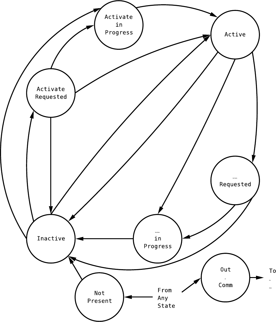
7.6. ENTITY HOT-SWAP 107
Figure 7.2: Complex Hot-Swap state machine
108 CHAPTER 7. ENTITIES
enum ipmi_hot_swap_states curr_state,
void *cb_data,
ipmi_event_t *event);
int ipmi_entity_add_hot_swap_handler(ipmi_entity_t *ent,
ipmi_entity_hot_swap_cb handler,
void *cb_data);
int ipmi_entity_remove_hot_swap_handler(ipmi_entity_t *ent,
ipmi_entity_hot_swap_cb handler,
void *cb_data);
This is a standard event handler as described in section 2.2.5 on page 20
7.6.3 Hot-Swap Activation and Deactivation
Devices that have the ability to control power and request power up or removal have some special handling
that may be required. Note that some systems may only support a s ubse t of these operations, reference the
documentation for the system for more details.
When a device is inserted that has these capabilities, there is gener ally some way to signal that the device
is ready to be powe red up. In ATCA, for instance, the operator will insert the card and the entity for the
card will go from no t pre sent to inactive state. When the operator closes the lock-latch, that signals the
system to g o to activation requested state.
If a device is in the inactive state, the management software using OpenIPMI can use the following
function to force it into activation requested state:
int ipmi_entity_set_activation_requested(ipmi_entity_t *ent,
ipmi_entity_cb done,
void *cb_data);
This can occur if an entity has been moved to the inactive state by the management software then the entity
needs to be powered up again. If an entity is sitting in the inactive state but does not support this, then
this call will return ENOSYS and the e ntity can be moved directly to active state.
To move an entity to active s tate (either from inactive or activation requested state), use the following
function:
int ipmi_entity_activate(ipmi_entity_t *ent,
ipmi_entity_cb done,
void *cb_data);
This will powe r the entity up and move it to active state.
Deactivation is similar, but not quite the sa me. The operator directly working on the device can request
a r e moval using some mechanism. In ATCA, for instance, the operator can open the lock latch on the card
and the card entity will move from active to deac tivatio n requested state. Note that unlike activation, there
is no way for system management software to request a move to deactivation requested state. It’s not really
required, since it can request that the entity go directly to inactive state.
To move from either active (or really any state in the activation pr ocess) or deactivation req uested state
to inactive state, the function:
7.7. FRU DATA 109
int ipmi_entity_deactivate(ipmi_entity_t *ent,
ipmi_entity_cb done,
void *cb_data);
is used.
7.6.4 Auto Activation and Deactivation
Some systems allow the system management software to sp e cify a po licy to execute when a device is inserted
or a removal is requested. Basic ally, the time from an activate r e quest to when an activation is automatically
started can be specified. The time from a deactivate request to when an dea ctivation is automatically started
can be specified. The following functions can be used to read and update these times:
int ipmi_entity_get_auto_activate_time(ipmi_entity_t *ent,
ipmi_entity_time_cb handler,
void *cb_data);
int ipmi_entity_set_auto_activate_time(ipmi_entity_t *ent,
ipmi_timeout_t auto_act,
ipmi_entity_cb done,
void *cb_data);
int ipmi_entity_get_auto_deactivate_time(ipmi_entity_t *ent,
ipmi_entity_time_cb handler,
void *cb_data);
int ipmi_entity_set_auto_deactivate_time(ipmi_entity_t *ent,
ipmi_timeout_t auto_deact,
ipmi_entity_cb done,
void *cb_data);
The timeouts are s tandard OpenIPMI time values, which are in nanoseconds. These will return ENOSYS
if the ope ration is not suppor ted. They will return EINVAL if the time is out of range. To disable auto-
activation and dea c tiviation, the time may be set to IPMI_TIMEOUT_FOREVER. To cause the transitions to
occur immediately, set the value to IPMI_TIMEOUT_NOW.
7.7 FRU Data
OpenIPMI supports fetching all the FRU data supported by the IPMI spec, as well as SPD data in DRAMs.
It also supports plugins for handling other types of FRU data that can be provided for OEM data. It is
able to fetch and modify all the standard data and all the custom data stored in multi-records and has a
multirecord decoder plugin interface w ith the standard multirecords implements, along with some ATCA
record decoders. SPD data (and other data types, unless they provide their own interfaces) can only be
decoded. Standard FRU data specified by the IPMI spe c c an be decoded and written.
7.7.1 Reading FRU Data
The FRU data interface has two separate interfaces fetching data data from a FRU data object. One is
a generic interface that works with all FRU data type, including SPD or OEM data. The other is an
IPMI-specified FRU interface that only works with the FRU data format specified by IPMI.

110 CHAPTER 7. ENTITIES
Generic FRU Data Interface
The generic FRU interface repre sents the FRU data as a tre e -structured hierarchy of data. Each level of the
tree has a “node”. The fields in a node are indexed by number and may contain both data elements and
sub-nodes.
Two types of nodes exist. A record node is a set of named fields. The “name” of each field will be
returned and the “intval” when the node itself is fetched will be −1 . An array node c ontains a set of
unnamed elements. The “name” of each field will be returned as NULL and the “intval” will be the number
of elements in the array.
The nodes are refcounted. If you are given a node, you must free the node using ipmi_fru_put_node()
when you are done with it.
To fetch the root node of a FRU data object, use the function:
int ipmi_fru_get_root_node(ipmi_fru_t *fru,
const char **name,
ipmi_fru_node_t **node);
This function returns the name of the FRU, either “SPD FRU” or “standard FRU” or so me other OEM
name and the actual root node. If either of these is NULL, it will be ignored. The r oot node is always a
record node.
To fetch individual fields from a record, use:
int ipmi_fru_node_get_field(ipmi_fru_node_t *node,
unsigned int index,
const char **name,
enum ipmi_fru_data_type_e *dtype,
int *intval,
time_t *time,
double *floatval,
char **data,
unsigned int *data_len,
ipmi_fru_node_t **sub_node);
The index is a contiguous range from zero that holds every field. So you can iterate thro ugh the indexes
from 0 until it returns E INVAL to find all the fields. If a field is not present in the FRU data, this will return
ENOSYS. Note that later fields may still be pres e nt.
The name returns the string name for the index. Note that the indexes may change b etween release, so
don’t rely on absolute numbers. The names will remain the s ame, so you can rely on those.
The dtype field will be se t to the data type. The following values are returned:
IPMI
FRU DATA INT se ts intval
IPMI
FRU DATA TIME sets time
IPMI FRU DATA ASCII sets data and data_len
IPMI
FRU DATA BINARY sets data and data_len
IPMI FRU DATA UNICODE sets data and data_len

7.7. FRU DATA 111
IPMI
FRU DATA BOOLEAN sets intval
IPMI FRU DATA FLOAT sets floatval
IPMI FRU DATA SUB NODE sets sub_node. intval will be -1 if it is not an array, or the array length if it is
an array.
Note that if data is returned in data, you must free the data when you are done with ipmi_fru_data_free().
Any of the return values may be passed NULL to ignore the data.
Printing all the FRU data or searching for a data item by name can easily be accomplished using rec ursion.
IPMI-specific FRU Data Interface
The generic interface should be used for applications that only read the FRU data. For applications that also
write the data, another interface is available tha t allows individual data items to be specifica lly addressed
and modified and the data areas of the FRU data to be modified, if they need to be resized, created, or
deleted.
IPMI FRU Data Organization FRU data is organized into areas, and the are as are organized into
fields. The areas are:
internal
use
chassis
info
board info
product info
multi
record
An area may or may not b e pr e sent. An area, if pre sent, may have required fields and “custom” fields.
The require d fields ca n be fetched by name, the custom fields are fetched by index number. Note that you
don’t need to know anything about areas if you are just fetching data from the FRU, but you need to know
about them to modify FRU data.
There are a very lar ge number of FRU varia bles and they are fairly well defined in the IPMI FRU
document; see that document and the ipmiif.h include file for details on the FRU data .
Fe tching FRU Data from a FRU Some fields are integers, some are time values, and some are strings.
Each type has its own fetch type. The integer and time values only return the one va lue that is returned.
The string functions have a “type” function, a “len” function, and a function to actually get the strings.
For instance:
int ipmi_fru_get_chassis_info_part_number_len(ipmi_entity_t *entity,
unsigned int *length);
int ipmi_fru_get_chassis_info_part_number_type(ipmi_entity_t *entity,
enum ipmi_str_type_e *type);
int ipmi_fru_get_chassis_info_part_number(ipmi_entity_t *entity,
char *str,
unsigned int *strlen);
112 CHAPTER 7. ENTITIES
The “len” function returns the length of the string. The “type” function returns the type of string per
standard OpenIPMI string handling. See section A.1 on page 157 for more details. The last function returns
the actual string. The integer that strlen points to must be set to the length of the str array. Upon return,
the integer that strlen p oints to will contain the actual length. If ther e is not enough space for the whole
string, the beginning of the string that fills the a rray will be copied in. All these functions r e tur n an error;
the only current return is ENOSYS if the par ameter is not present.
You may also fetch fru data (except for multi-records) through a single general function. It is a necessarily
complex interface. The function is:
int ipmi_fru_get(ipmi_fru_t *fru,
int index,
char **name,
int *num,
enum ipmi_fru_data_type_e *dtype,
int *intval,
time_t *time,
char **data,
unsigned int *data_len);
The index is a contiguous range from zero that holds every FRU data item. So you can iterate thr ough the
indexes fro m 0 until it returns EINVAL to find a ll the names.
The name returns the string name for the index. Note that the indexes may change b etween release, so
don’t rely on absolute numbers. The names will remain the s ame, so you can rely on those.
The number is a pointer to an integer with the number of the item to get within the field. Some fields
(custom recor ds ) have multiple items in them. The first item will be zero, and the integer here will be
upda ted to refere nce the next item. When the last item is reached, the field will be updated to -1. For fields
that don’t have multiple items, this will not modify the value num points to, so you can use that to detect
if indexes are used for the item.
The dtype field will be set to the data type. If it is an integer value, then intval will be set to w hatever
the value is. If it is a time value, then the time field will be filled in. If it is not, then a block of data will be
allocated to hold the field and placed into data, the length of the data will be in data_len. You must free
the data when you are done with ipmi_fru_data_free().
This function Returns EINVAL if the index is out of range, ENOSYS if the particular index is not supported
(the name will still be set), or E2BIG if the num is too big (a gain, the name will be set).
Any of the return values may be passed NULL to ignore the data.
Writing FRU Data to a FRU OpenIPMI supports writing FRU data. This is a very dangerous oper-
ations and sho uld not be done by general code. There are no locks on the FRU data, so multiple writers
can easily corr upt the data. But for doing FRU data updates, OpenIPMI c an be used to fetch, modify, and
write the FRU data assuming proper care is taken.
To write to the FRU, you must first fetch it by a llocating it. If the FRU da ta currently in the fru is
corrupt, you will get erro rs, but as long as the data length of the FRU is non-zero you can still mo dify it
and write it back out.
After the FRU has been fetched, you may then modify the contents. Remember that each field of a FRU
is in an area. To incre ase the size of a field or add a new field, it’s area must have enough s pace.
You may change the size of an area by increasing or decreasing its length. You may also add a new area,
but it must be one of the suppo rted types . You must, however, ma ke sure there is enough empty space to
7.7. FRU DATA 113
after the area. Op enIPMI will not rearrange the areas to make space , you have to do that yourself. So you
may have to change the offset of an area (and other areas) to make space. The following functions are for
working with areas:
int ipmi_fru_add_area(ipmi_fru_t *fru,
unsigned int area,
unsigned int offset,
unsigned int length);
int ipmi_fru_delete_area(ipmi_fru_t *fru, int area);
int ipmi_fru_area_get_offset(ipmi_fru_t *fru,
unsigned int area,
unsigned int *offset);
int ipmi_fru_area_get_length(ipmi_fru_t *fru,
unsigned int area,
unsigned int *length);
int ipmi_fru_area_set_offset(ipmi_fru_t *fru,
unsigned int area,
unsigned int offset);
int ipmi_fru_area_set_length(ipmi_fru_t *fru,
unsigned int area,
unsigned int length);
int ipmi_fru_area_get_used_length(ipmi_fru_t *fru,
unsigned int area,
unsigned int *used_length);
The used_length variable tells how much o f the length of the FRU is actually used. Note that area offsets
and length must be multiples of 8.
To change the value of a field, you will use functions of the fo r m:
int ipmi_fru_set_chassis_info_type(ipmi_entity_t *entity,
unsigned char type);
int ipmi_entity_set_chassis_info_part_number(ipmi_entity_t *entity,
enum ipmi_str_type_e *type);
char *str,
unsigned int strlen);
int ipmi_fru_set_chassis_info_custom(ipmi_fru_t *fru,
unsigned int num,
enum ipmi_str_type_e type,
char *str,
unsigned int len);
These set the fields to the given values. If you set a required field to a NULL string, it will clear the value of
the string. If you set a multi-record or custom string to a NULL string, it will delete the record at the given
number.
Like the ipmi_fru_get function, the following functions allow setting FRU variables by index:
int ipmi_fru_set_int_val(ipmi_fru_t *fru,
int index,
114 CHAPTER 7. ENTITIES
int num,
int val);
int ipmi_fru_set_time_val(ipmi_fru_t *fru,
int index,
int num,
time_t time);
int ipmi_fru_set_data_val(ipmi_fru_t *fru,
int index,
int num,
enum ipmi_fru_data_type_e dtype,
char *data,
unsigned int len);
The num field is ignored if the par ticular index does not suppor t more than one field (is not a custom field).
When adding, if the num field is a field that already exists, it will be replaced or updated. If num is beyond
the last element of the pa rticular item, a new item will be added onto the end, it will not be added at the
sp e c ific index.
To write the FRU data back out after you have modified it, use the following function:
int ipmi_fru_write(ipmi_fru_t *fru, ipmi_fru_fetched_cb done, void *cb_data);
7.8 Entity SDRs
TBD - write this

Chapter 8
Sensors
Sensors, of course, are probably the most interesting part of IPMI. Really, everything else is there so the
sensors may be known and monitored. Unfortunately, sensors are also the most complicated part of IPMI.
OpenIPMI is really unable to hide a lot of this complexity, it is passed on to the user, so exp e c t to have to
do some reading and understanding.
IPMI defines two basic different types of sensors. Threshold sensors monitor “analog” things like tem-
perature, voltage, or fan s peed. Discrete sensors monitor events or states, like entity presence, software
initialization progres s, or if external p ower is applied to the system. Table 8.1 describes the basic types of
sensors.
Table 8.1: Event/Reading Type Codes
Value # Description
8.1 Sensor Events
Both threshold and discrete sensors may generate events. This is optional, the SDR fo r the sensor describes
the s e ns or’s event support.
Some sensors support each individual bit or state being e nabled or disabled. Others may only support
events for the whole sensor being enabled or disabled. Still others may only support a global enable for the
entire MC.
8.2 Rearm
“Rearm” means setting the senso r so it will go off again.
TBD - write this.
8.3 Threshold Sensors
Threshold sensors report their r eadings in values from 0-255. OpenIPMI makes every effort to convert
this to a floating-point value for you to use. IPMI defines standard ways to convert values using various
115
116 CHAPTER 8. SENSORS
formulas. OpenIPMI implements all these and provides ways for OEM functions to plug in to provide their
own co nverters. If you have a sensor that cannot be re presented using the standar d mechanisms, you need
to get the OEM algorithms for this and implement them in an OEM plug-in for the sensor.
8.3.1 Threshold Sensor Events
You may have events on a thresho ld sensor by specifying values (called thresholds) where you want the sensor
to report an event. Then you can enable the events for the specific thresholds. Not all senso rs support all
thresholds, some c annot have their events enabled and others cannot have them disabled. The capabilities
of a sensor may all be queried by the user to determine wha t it can do. When the value of the sensor goes
outside the thr e shold an event may be generated. An event may be generated when the value goes back into
the threshold.
Events for threshold sensors are mind-bogglingly complicated. Each threshold has four different pos sible
events tha t can be supported. Only two of them make sense to support for any given threshold, thankfully.
And a sensor can have six different thresholds.
IPMI supports events on g oing below (going low) the threshold and going above the threshold (going
high). For each of those, it supports an assertion and deassertion event. Most sensors are either a lower bound
(and would thus support an eventgoing below the threshold) or an upper bound (and wo uld thus support an
event going a bove the threshold). Figure 8.1 on the next page shows an upper and lower thres hold sensor.
When the value of an upper threshold sensor goes above the threshold, tha t is a n assertion going high. When
it goes back below the threshold, that is a deassertion going high. On a lower threshold, going below the
threshold is a asser tion going low. When the value goes back above the thre shold, it is an deassertion going
low.
Each sensor may have s ix different thresholds:
upper non-recoverable
upper critical
upper non-critical
lower non-critical
lower critical
lower non-recoverable
The meanings of these ar e not defined by IPMI, but the meanings are pretty obvious. You may ask, though,
why there are both upper and lower thresholds and sepa rate going high and going low events. A going low
event is kind of silly on an upper threshold, for instance. The reasoning is not in the spec, but it may be that
there are sensors where the “middle” of the range is not ok. So for instance, it may be ok if the temperature
is above 100C or below 5C, but the range between those values is not ok. This is extremely unlikely, but
this type of structure allows it.
8.3.2 Hysteresis
Threshold sensors may have hysteresis, meaning that when the threshold goes on above or below the specified
value, the transition po int where the threshold goes off is somewhat below or above the given value. For
instance, if you want a fan spee d sensor to go off when it goes below 150 RPM, if the fan is hanging right
around 150 RPM, the sensor may be constantly sending you events as it goes slightly above and slightly
below 150 RPM, which is bad because it can overload the system management software. The hysteresis for
the fan might be set at 10 rpm, which means that if the speed goes below 150 RPM, then it must go above
160 RPM for the threshold to be disabled. Hysteresis may be settable or may be fixed for the sensor .
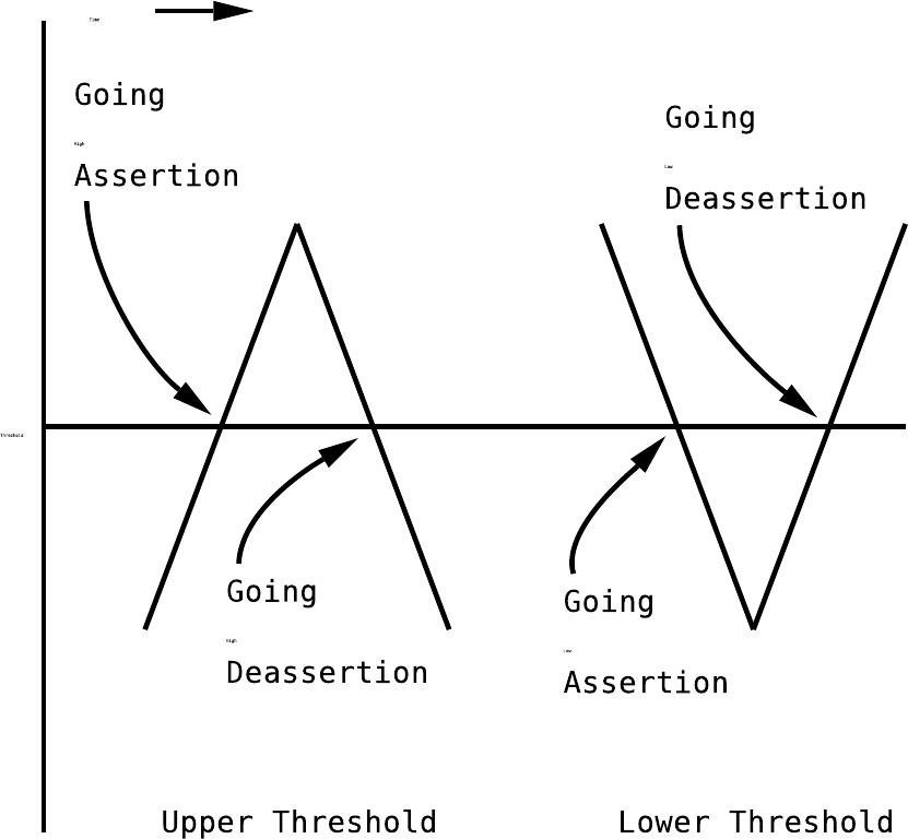
8.3. THRESHOLD SENSORS 117
Figure 8.1: Examples of thresholds

118 CHAPTER 8. SENSORS
Figure 8.2 on page 121 shows an example of going high and going low thresholds with hysteresis. Notice
that the deassertion events don’t get triggered right at the threshold, but as some po int beyond the threshold.
There is only one pair of hysteresis values for a sensor. That pair is used fo r all thresholds in the s e nsor.
One of the members of the pair is a positive threshold, meaning that is is applied to thresholds that go over
a specific value. The value must go that much below the threshold before the threshold goes back in range.
The o ther member is a negative threshold, meaning that it is applied to thresholds that go below a given
value. The value must go that much above the thres hold before the threshold goes back in range .
8.4 Discrete Sensors
Discrete sensors report their readings in a 16-bit bitmask, each bit generally representing a discrete state.
For instance, consider the slot/connector sensor. Bit 0 tells if there is a fault. Bit 2 tells if a device is pres e nt
in the slot. Bit 5 tells if power is off on the slot. Ea ch bit tells a completely independent state and they may
each be zero or one independently.
You enable events on the sensor by specifying which bits you want to generate events. Like threshold
sensors, these events may or may not b e user-controllable. The capabilities of the s e nsor may be fetched by
the user.
Table 8.2: Sensor Types and Codes
Parameter # Description
8.5 IPMI Commands Dealing with Sensors
TBD - write this
8.6 Using Sensors in OpenIPMI
As mentioned before, IPMI sensors are very complicated. OpenIPMI attempts to hide as much of this
complexity as it can, but it ca n only do so much.
So starting at the beginning, the first thing you need to know about a sensor is its type. You fetch that
with the function:
int ipmi_sensor_get_event_reading_type(ipmi_sensor_t *sensor);
This returns a value from the following table. The names in this table are shortened, all these begin with
IPMI EVENT READING TYPE . The values are:
THRESHOLD The sensor monitors an analog value. All thresho ld sensors have this
value.
DISCRETE USAGE These are DMI-based usa ge states . Valid offsets are:
00h - transition to idle
01h - transition to active
02h - transition to busy

8.6. USING SENSORS IN OPENIPMI 119
DISCRETE STATE Monitors the value of a state. Valid values are:
00h - state deasserted
01h - state asserted
DISCRETE PREDICTIVE
FAILURE
This is us e d to know if an entity is about to fail, but is still operations.
Valid values are:
00h - predictive failure dea sserted
01h - predictive failure asserted
DISCRETE LIMIT
EXCEEDED
This is used to tell if a limit ha s been exceeded. Valid values are:
00h - limit not exceeded
01h - limit exceeded
DISCRETE
PERFORMANCE MET
This is used to tell if system performance is meeting expectations.
Valid values are:
00h - performance met
01h - performance not met
DISCRETE SEVERITY This is used to know if an entity is in trouble or other state information.
Valid values are:
00h - transition to ok
01h - transition to non-critical from ok.
02h - transition to critical from less critical.
03h - transition to non-recoverable from less critical.
04h - transition to non-critical from more critical.
05h - transition to critical from no n-recoverable.
06h - transition to non-recoverable.
1
07h - monitor
08h - informational
The actual mea ning of these is not defined by the spec.
DISCRETE DEVICE
PRESENCE
This is a pre sence sensor to know when an entity is present or not.
Note that OpenIPMI uses this for entity presence if it is available.
Valid values are:
00h - entity not present
01h - entity present
DISCRETE DEVICE
ENABLE
This tells if a device is enabled. Valid values are:
00h - device dis abled
01h - device e nabled
1
This state seems rather silly and is probably not used.

120 CHAPTER 8. SENSORS
DISCRETE
AVAILABILITY
This tells the current availability state of the device. Valid values are:
00h - transition to r unning
01h - transition to in test
02h - transition to power off
03h - transition to on line
04h - transition to off line
05h - transition to off duty
06h - transition to deg raded
07h - transition to power save
08h - install error
DISCRETE
REDUNDANCY
This shows the redundancy state of an entity. Valid values are:
00h - Fully redundant, the e ntity has full redundancy.
01h - Redundancy lost, this is reported if redundancy has been lost
at all.
02h - Redundance degraded, the system is still redundant but is miss-
ing s ome resources (like the system has four fans and only two
are running).
03h - Transition from fully redundant to non-redundant: sufficient
resource. The entity has lost redundancy but has sufficient re-
sources to continue normal operation.
04h - Transition from non-redundant:sufficient resources to non-
redundant:insufficient resource. The e ntity has lost enough re-
sources to continue normal operation.
05h - Transition from fully redundant to non-redundant: sufficient
resource. The entity has lost redundancy but has sufficient re-
sources to continue normal operation.
06h - No n-redundant:insufficient resources. entity has lost re dun-
dancy and lost enoug h resources to continue normal operation.
07h - Transition from redundant to redundancy degraded. The unit
has lost some redundancy but is still redundant.
08h - Transition from redundancy lost to redundancy degraded. The
entity had lost redundancy and has re gained some redundancy,
but is not fully redundant.
DISCRETE ACPI POWER The current ACPI power state of the sy stem. Valid values are:
00h - D0 power state
01h - D1 power state
02h - D2 power state
03h - D3 power state
SENSOR SPECIFIC This setting means that the offsets in the sensor are dependent on the
sensor type. This is only for discrete sensors.
Note that for some operations, thres hold sensors and discrete sensor have different functions, and some
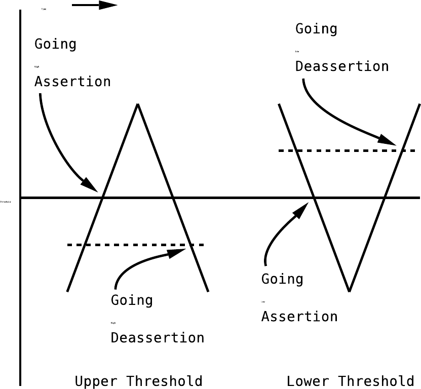
8.6. USING SENSORS IN OPENIPMI 121
Figure 8.2: Examples of hysteresis

122 CHAPTER 8. SENSORS
other functions work a little differently.
To know the type of sensor, the function:
int ipmi_sensor_get_sensor_type(ipmi_sensor_t *sensor);
returns the type. T he returns values for this are integer defines that start with IPMI SENSOR TYPE and
have the specific values defined in the following table. Note that discrete sensors in this list have define bit
settings; those settings ar e also defined in this list.
TEMPERATURE
VOLTAGE
CURRENT
FAN
PHYSICAL SECURITY The chassis was opened or accessed.
00h - General chassis intrusion
01h - Drive bay intrusion
02h - I/O card a rea intrusion
03h - Proce ssor area intrusion
04h - LAN cable is unplugged
05h - Unauthorized dock/undock
06h - Fan area intrusion (including unauthorized hot-plugs of fans).
PLATFORM SECURITY
00h - The spec says “Secure Mode (Front Panel Lockout) Violation
attempt”. The meaning of this is unknown.
01h - User pre-boot password failure.
02h - Setup pre-boot password failure.
03h - Network pre-boot password failure.
04h - Other pre-boot password failure.
05h - Out-of-band pre-boot password failure.
PROCESSOR Various processor failures. Most of these ar e very Intel processor cen-
tric, you may need to re ference the processor manual for the meaning
of the failure.
00h - IERR
01h - Thermal Trip
02h - FRB1/BIST failure
03h - FRB2/Hang in POST failure, if the failure is believed to be
due to a processor failure.
04h - FRB3/P rocessor Startup/Initialization failur e (CPU didn’t
start).
05h - Configuration Error
06h - SMBIOS “Uncorrectable CPU-complex error”
07h - Proce ssor presence detected
08h - Proce ssor disabled
09h - Terminator presence detected

8.6. USING SENSORS IN OPENIPMI 123
POWER SUPPLY
00h - Presence detected
01h - Failure detected
02h - Predictive failur e . This probably means that the p ower supply
is still working but may fail soon.
03h - AC lost
04h - AC lost or out-of-rang e
05h - AC present but out of range
POWER UNIT
00h - Power off
01h - Power cycle
02h - 240VA power down
03h - Interlock power down
04h - AC lost
05h - Soft p ower control failure (unit did not response to request)
06h - Failure detected
07h - Predictive failure. This probably means that the power unit is
still working but may fail soon.
COOLING DEVICE
OTHER UNITS
BASED SE NSO R
The sensor is a threshold sensor, but not one specified directly by the
sp e c . The units c an be fetched with the calls to get the units.
MEMORY
00h - Corr e c table memory error
01h - Uncorrectable memory error
02h - Parity error
03h - Memory scrub failed, probably stuck bit
04h - Memory device disabled
05h - Reached log limit for correctable memory errors
DRIVE SLOT
POWER MEMORY
RESIZE
SYSTEM FIRMWARE
PROGRESS
Information about the system firmware (BIOS). In an event, the event
data 2 may give further information about the err or. See section 10.2
for more info.
00h - System firmware error (power-on-self-test error)
01h - System firmware hang
02h - System firmware progress

124 CHAPTER 8. SENSORS
EVENT LOGGING
DISABLED 00h - Correctable memory error logging disabled
01h - Event logging has been disabled for the sensor specified in
the event information. In a n event, event data provides more
information ab out the event, see s e ction 10.2 for more info.
02h - Log area cleared
03h - All event logging disabled
WATCHDOG 1 This is for IPMI version 0.9 and old 1.0 only. Later 1.0 and newer
sp e c s use the watchdog 2 sensor type.
00h - BIOS watchdog reset
01h - OS watchdog reset
02h - OS watchdog shutdown
03h - OS watchdog power down
04h - OS watchdog power cy c le
05h - OS watchdog NMI or diagnostic interrupt
06h - OS watchdog expired, status only
07h - OS watchdog pre-timeout interrupt, not NMI
SYSTEM EVENT
00h - System reconfigured
01h - OEM system boot event
02h - Undetermined system hardware failure
03h - Entry added to the auxilliar y log. In a n event, event data
provides more information about the event, see section 10.2 for
more info.
04h - PEF action. In an event, event data provides more information
about the event, see section 10.2 fo r more info.
CRITICAL INTERRUPT
00h - Front panel NMI/Diagnostic interrupt
01h - Bus timeo ut
02h - I/O channel check NMI
03h - Software NMI
04h - PCI PERR
05h - PCI SERR
06h - EISA fail s afe timeout
07h - Bus correctable error
08h - Bus uncorrectable error
09h - Fatal NMI (port 61h, bit 7)

8.6. USING SENSORS IN OPENIPMI 125
BUTTON
00h - Power button presse d
01h - Sleep button pressed
02h - Reset button pressed
MODULE BOARD
MICROCONTROLLER
COPROCESSOR
ADD IN CARD
CHASSIS
CHIP SET
OTHER FRU
CABLE INTERCONNECT
TERMINATOR
SYSTEM BOOT
INITIATED 00h - Power up
01h - Hard reset
02h - Warm reset
03h - User requested PXE boot
04h - Automatic boot to diagnostic
BOOT ERROR
00h - No bootable media
01h - Non-bootable disk in drive
02h - PXE server not found
03h - Invalid boot sector
04h - Timeout waiting for use r selectio n of boot source
OS BOOT
00h - A: b oot completed
00h - C: boot completed
00h - PXE b oot completed
00h - Diagnostic boot completed
00h - CDROM boot c ompleted
00h - ROM boot completed
00h - Boot completed, boot device not specified
OS CRITICAL STOP
00h - Stop during OS load or initialization
01h - Stop during OS operation

126 CHAPTER 8. SENSORS
SLOT CONNECTOR Note that ready for installation, ready for removal, and power states
can transition tog e ther. In an event, e vent data provides more infor-
mation about the event, see section 10.2 for mo re info.
00h - Fault status
01h - Identify status
02h - Device installed (includes doc events)
03h - Ready for device installation. This generally means that the
power is off.
04h - Ready for device removal.
05h - Power is off
06h - Removal request. This generally means that the user has as-
serted some mechanism that requests removal.
07h - Interlock. This is generally s ome mechanical device that dis-
ables power to the s lot. Assertion means that the disable is ac-
tive.
08h - Slot is disabled.
SYSTEM ACPI
POWER STATE 00h - S0/G0 “Working ”
01h - S1 “Sleeping, sy stem h/w and processor context maintained”
02h - S2 “Sleeping, processor context lost”
03h - S3 “Sleeping, sy stem h/w and processor context lost, memory
maintained”
04h - S4 “non-volatile sleep or suspend to disk”
05h - S5/G2 “soft off”
06h - S4/S5 soft-off, particular S4 /S5 state cannot be determined.
07h - G3 “Mechanical off”
08h - Sleeping in an S1, S2, or S3 state, par ticular state c annot be
determined.
09h - G1 sleeping, S1-S4 state cannot be determined
0Ah - S5 state entered by override
0Bh - Legacy on state
0Ch - Legacy off state
0Eh - Unknown
WATCHDOG 2 This is for newer IPMI 1.0 systems and later spec s. In an event, event
data provides more information about the event, see section 10.2 for
more info.
00h - Timer expired, status only, no action
01h - Hard reset
02h - Power down
03h - Power cycle
08h - Timer interrupts.

8.6. USING SENSORS IN OPENIPMI 127
PLATFORM ALERT Used for monitoring the platfor m management firmware, status can be
fetched and events gener ated on platform management actions.
00h - Page sent
01h - LAN alert sent
02h - Event trap sent per IP MI PET specification
03h - Event trap sent using OEM format
ENTITY PRESENCE This is the sensor used to tell if an entity is present or not. This applied
to the e ntity the sensor is attached to.
00h - Entity is present
01h - Entity is absent
02h - Entity is present but disabled
MONITOR ASIC IC
LAN
00h - LAN heartbeat lost
01h - LAN heartbeat present
MANAGE MENT
SUBSYSTEM HEALTH 00h - Sensor access degraded or unavailable
01h - Controller access degraded or unavailable
02h - Management controller offline
03h - Management controller unavailable
BATTERY
00h - Battery is low
01h - Battery failed
02h - Battery is pr e sent.
Strings are available from the sensor that describe the sensor type and event reading type. Note that
these may be set to valid values by O EM code even if the values are OEM, so these can be very useful.
char *ipmi_sensor_get_sensor_type_string(ipmi_sensor_t *sensor);
char *ipmi_sensor_get_event_reading_type_string(ipmi_sensor_t *sensor);
As well as the strings, the specific r e ading information from the above table is also available, supply the
sensor type and offset and a string is returned. The function is:
char *ipmi_sensor_reading_name_string(ipmi_sensor_t *sensor, int offset);
8.6.1 General Information About Sensors in OpenIPMI
The following section applies to all sens or types.

128 CHAPTER 8. SENSORS
Sensor Entity Information
Every sensor is ass ociated with a specific entity, these calls let you fetch the entity informatio n. The following
calls return the numeric entity id and instance:
int ipmi_sensor_get_entity_id(ipmi_sensor_t *sensor);
int ipmi_sensor_get_entity_instance(ipmi_sensor_t *sensor);
Generally, though, that is note wha t you want. You want the actual entity object, which may be fetched
with the following:
ipmi_entity_t *ipmi_sensor_get_entity(ipmi_sensor_t *sensor);
Note that the entity is refcounted when the sensor is claimed, so the entity will exist while you have a valid
reference to a sensor it contains.
Sensor Name
The SDR contains a string giving a name for the sens or. This is useful for printing out sensor information.
The functions to get this are:
int ipmi_sensor_get_id_length(ipmi_sensor_t *sensor);
enum ipmi_str_type_e ipmi_sensor_get_id_type(ipmi_sensor_t *sensor);
int ipmi_sensor_get_id(ipmi_sensor_t *sensor, char *id, int length);
See appendix A.1 for more information about these s trings.
The function
int ipmi_sensor_get_name(ipmi_sensor_t *sensor, char *name, int length);
returns a fully qualified name for the sensor with the entity name pre pended. The name array is filled with
the name, up to the length given. This is useful for printing string names for the sensor.
Sensor Event Support i n OpenIPMI
Sensors may support event enables in different ways. The following function returns what type of event
enable is supported:
int ipmi_sensor_get_event_support(ipmi_sensor_t *sensor);
The return values ar e all prepended with IPMI
EVENT SUPPORT , values are :
PER STATE Each individual state or threshold may individually have its events
turned off and on. This means that the individual thresholds and
states may be individually enabled.
ENTIRE SENSOR The entire sensor may have events enabled and disabled using the
events enabled s e tting when setting the event enables. Section 8.6.1
describes this setting.
GLOBAL ENABLE Events may only be enabled and disabled for the whole managment
controller. Events are disabled by setting the event rec e iver to 00h, or
enabled by setting them to the proper event receiver. See section 4.1.5
for more details.
NONE The sensor does not support events.
8.6. USING SENSORS IN OPENIPMI 129
Note that the more general event enables work and ove rride the more specific ones, so if, for instance, a
sensor supports per-state event enables, it will als o support the entire sensor and global enables. The entire
sensor enable being off will override all per-state enables. The globa l enable will turn off all events from a
management controller no matter what other settings a re present.
To receive events from a sensor, an event handler must be register ed. An event handler may also be
dynamically removed. The following functions do this for discrete sens ors:
typedef int (*ipmi_sensor_discrete_event_cb)(
ipmi_sensor_t *sensor,
enum ipmi_event_dir_e dir,
int offset,
int severity,
int prev_severity,
void *cb_data,
ipmi_event_t *event);
int ipmi_sensor_add_discrete_event_handler(
ipmi_sensor_t *sensor,
ipmi_sensor_discrete_event_cb handler,
void *cb_data);
int ipmi_sensor_remove_discrete_event_handler(
ipmi_sensor_t *sensor,
ipmi_sensor_discrete_event_cb handler,
void *cb_data);
The following functions do this for thres hold sensors:
typedef int (*ipmi_sensor_threshold_event_cb)(
ipmi_sensor_t *sensor,
enum ipmi_event_dir_e dir,
enum ipmi_thresh_e threshold,
enum ipmi_event_value_dir_e high_low,
enum ipmi_value_present_e value_present,
unsigned int raw_value,
double value,
void *cb_data,
ipmi_event_t *event);
int ipmi_sensor_add_threshold_event_handler(
ipmi_sensor_t *sensor,
ipmi_sensor_threshold_event_cb handler,
void *cb_data);
int ipmi_sensor_remove_threshold_event_handler(
ipmi_sensor_t *sensor,
ipmi_sensor_threshold_event_cb handler,
void *cb_data);
This function should genera lly be registered in the entity callback tha t rep orts the sensor being added, so
that no events will be missed. This is a standard event ha ndler as defined in section 2.2.5 on page 20.
130 CHAPTER 8. SENSORS
Sensor/Entity Existance Interaction
Some s e nsors are present e ven if the entity they are attached to is no t pre sent. The following will return
true if the entity should be ig nore if the entity is not present. It will return false if the sensor is present even
when the entity is not present.
int ipmi_sensor_get_ignore_if_no_entity(ipmi_sensor_t *sensor);
Sensor States
When reading the value of a sensor or handling an even, a state da ta structure is generally available in a
read-only data str uctur e . This tells the state of the various thresholds or bits in the sensor. This is an
opaque data str uctur e , you do not have acc e ss to any of the contents. The data structure is defined as:
typedef struct ipmi_states_s ipmi_states_t;
To keep your own copy of a states data structure, you may allocate and co py one using the following
functions:
unsigned int ipmi_states_size(void);
void ipmi_copy_states(ipmi_states_t *dest, ipmi_states_t *src);
This allows you to find the size and copy the information in o ne o f these structures . For example, to make
your own copy, do something like:
my_states = malloc(ipmi_states_size());
if (!my_states)
handle_error()
else
ipmi_copy_states(my_states, states);
Information about the whole sensor is available using the following functions:
int ipmi_is_event_messages_enabled(ipmi_states_t *states);
int ipmi_is_sensor_scanning_enabled(ipmi_states_t *states);
int ipmi_is_initial_update_in_progress(ipmi_states_t *states);
If event messages are ena bled, then the sensor may generate events. If scanning is enabled, then the sensor is
“turned on” and working. If initial update is in progress, the information from the sensor is no t valid since
the s e ns or is still trying to get a valid reading.
Sensor Event State Information
The event state structure is an opaque structure that is used to control the event settings of a sensor, if
it supports at least individual sensor event control. This is much like the state data s tructure defined in
section 8.6.1, but it is used to contro l eve nt settings instead of just get the current state. The data structure
is defined as:
typedef struct ipmi_event_state_s ipmi_event_state_t;
8.6. USING SENSORS IN OPENIPMI 131
It is an opaque data structure, so you cannot directly access the contents o r directly declare one.
To create or keep your own copy o f a n event state data structure, you may allocate and copy one using
the following functions:
unsigned int ipmi_event_state_size(void);
void ipmi_copy_event_state(ipmi_event_state_t *dest, ipmi_event_state_t *src);
This allows you to find the size and copy the information in o ne o f these structures . For example, to make
your own copy, do something like:
my_states = malloc(ipmi_event_state_size());
if (!my_states)
handle_error()
else
ipmi_copy_event_state(my_states, states);
If you want to create one, allocate it as above and initialize it with
void ipmi_event_state_init(ipmi_event_state_t *events);
This c le ars all settings. The following functions are then available to set and get global items in the event
state:
void ipmi_event_state_set_events_enabled(ipmi_event_state_t *events, int val);
int ipmi_event_state_get_events_enabled(ipmi_event_state_t *events);
void ipmi_event_state_set_scanning_enabled(ipmi_event_state_t *events,int val);
int ipmi_event_state_get_scanning_enabled(ipmi_event_state_t *events);
void ipmi_event_state_set_busy(ipmi_event_state_t *events, int val);
int ipmi_event_state_get_busy(ipmi_event_state_t *events);
If events ar e enabled, then the sensor can generate events. This acts as an off switch for the whole sensor.
If events are enabled, and if per-state event enables are supported, then the individual state settings contr ol
which events are generated. Scanning means watching for events; if scanning is off then the senso r, in effect,
is turned off a nd will not report valid reading or generate events. If busy is true on a r e tur n from a query,
then the sensor is currently in busy with some operation and cannot be read.
See section 8.6.3 for discrete s e ns ors and section 8.6.2 on page 134 for thres hold events for the details on
setting the individual event enables.
Note that once you have created an event state, you have to send it to the sensor. Just creating and
setting the values doesn’t do anything directly to the sensor; it must be sent. To send them, use one of the
following:
int ipmi_sensor_set_event_enables(ipmi_sensor_t *sensor,
ipmi_event_state_t *states,
ipmi_sensor_done_cb done,
void *cb_data);
int ipmi_sensor_enable_events(ipmi_sensor_t *sensor,
ipmi_event_state_t *states,
ipmi_sensor_done_cb done,
void *cb_data);
132 CHAPTER 8. SENSORS
int ipmi_sensor_disable_events(ipmi_sensor_t *sensor,
ipmi_event_state_t *states,
ipmi_sensor_done_cb done,
void *cb_data);
The “set” function will set the states to exactly wha t is s et in the event state structure. The “enable”
function will only enable the states that are set in the event state structure. The “disable” function will
disable the events that are set in the event state structure. Note that the disable does not disable the events
that are not set, it really disables the events that are set. All of these functions will set the event enable
and scanning enable to the values in the event state structure.
To query the current event state settings, use the following function:
typedef void (*ipmi_sensor_event_enables_cb)(ipmi_sensor_t *sensor,
int err,
ipmi_event_state_t *states,
void *cb_data);
int ipmi_sensor_get_event_enables(ipmi_sensor_t *sensor,
ipmi_event_enables_get_cb done,
void *cb_data);
Appendex I on page 185 co ntains a program that demonstrates how to use many of the functions described
in this sec tion.
Rearm in OpenIPMI
TBD - write this.
int ipmi_sensor_get_supports_auto_rearm(ipmi_sensor_t *sensor);
int ipmi_sensor_rearm(ipmi_sensor_t *sensor,
int global_enable,
ipmi_event_state_t *state,
ipmi_sensor_done_cb done,
void *cb_data);
Initialization
When a sensor is stored in the main SDR repository of a system, the BMC may initialize certain aspects
of the sensor at power up. The following fetch if these aspec ts are initialized at power up. Note that “pu”
means “Power Up” in the following names.
int ipmi_sensor_get_sensor_init_scanning(ipmi_sensor_t *sensor);
int ipmi_sensor_get_sensor_init_events(ipmi_sensor_t *sensor);
int ipmi_sensor_get_sensor_init_thresholds(ipmi_sensor_t *sensor);
int ipmi_sensor_get_sensor_init_hysteresis(ipmi_sensor_t *sensor);
int ipmi_sensor_get_sensor_init_type(ipmi_sensor_t *sensor);
int ipmi_sensor_get_sensor_init_pu_events(ipmi_sensor_t *sensor);
int ipmi_sensor_get_sensor_init_pu_scanning(ipmi_sensor_t *sensor);

8.6. USING SENSORS IN OPENIPMI 133
8.6.2 Threshold Sensors in OpenIPMI
As mentioned before, threshold sens ors monitor analog values. This means that they have a lot of infor mation
about how to convert the values from the raw readings (the 0-255 value returned from the sensor) into useful
readings, what thresholds are supported, hysteresis settings, and a plethora of other settings. Lots of things
can be set up for threshold sensors.
Threshold Sensor Readings in OpenIPMI
The reading of a threshold sensor is done with the following:
typedef void (*ipmi_sensor_reading_cb)(ipmi_sensor_t *sensor,
int err,
enum ipmi_value_present_e value_present,
unsigned int raw_value,
double val,
ipmi_states_t *states,
void *cb_data);
int ipmi_sensor_get_reading(ipmi_sensor_t *sensor,
ipmi_reading_done_cb done,
void *cb_data);
Assuming there was no error, the value
present field will be set to one of the following:
IPMI NO VALUES PRESENT - Neither the raw or the converted values are present. Only the sta tes
are valid. This will be the case for thres holds sensors that cannot have their value read.
IPMI
RAW VALUE PRESENT - Only the raw value is present. T his will be the case if there was no
convers ion algorithm available for the sensor.
IPMI BOTH VALUES PRESENT - Both the raw and converted values are present.
The current states of the various thresholds (whether they are o ut of range or note) is retur ned in the
states parameter. To know if a senso r sets a thresho ld state setting when the value is read, use the following
function:
int ipmi_sensor_threshold_reading_supported(ipmi_sensor_t *sensor,
enum ipmi_thresh_e thresh,
int *val);
This may not mean that the threshold will generate events (although it will almost certainly mean that, the
sp e c is not clear on this). It is only defined to mean that the thresho ld is returned in the reading.
For threshold sensors, the function:
int ipmi_is_threshold_out_of_range(ipmi_states_t *states,
enum ipmi_thresh_e thresh);
will return true if the given threshold is out of range and false if not.

134 CHAPTER 8. SENSORS
Threshold Sensor Events in OpenIPMI
Section 8.6.1 on page 128 shows the genera l support for events for all sensor types. Threshold sensors have
their own special routines for handling the thresholds.
Thresholds in a sensor may be settable o r fixed and may or may not be able to be read. The function
int ipmi_sensor_get_threshold_access(ipmi_sensor_t *sensor);
returns the event threshold access support of the sensor, r etur n values are
IPMI
THRESHOLD ACCESS SUPPORT NONE - The sensor does not suppor t thresholds.
IPMI
THRESHOLD ACCESS SUPPORT READABLE - The sens or supports thresholds and their
values may be rea d with ipmi thres holds get, but c annot b e written.
IPMI
THRESHOLD ACCESS SUPPORT SETTABLE - The sensor supports thresholds and they
may be read and written.
IPMI
THRESHOLD ACCESS SUPPORT FIXED - The sensor supports thresholds and they are
fixed and may not be read or changed. ipmi get default sensor thresholds should return the fixed
values o f this sensor.
In addition to this, individual thresholds may be readable or settable individually. To find this, the
following functions will return true if a specific threshold is readable or settable, and false if not:
int ipmi_sensor_threshold_settable(ipmi_sensor_t *sensor,
enum ipmi_thresh_e threshold,
int *val);
int ipmi_sensor_threshold_readable(ipmi_sensor_t *sensor,
enum ipmi_thresh_e threshold,
int *val);
The sp e c ific threshold values in the enumeration are:
IPMI
LOWER NON CRITICAL
IPMI
LOWER CRITICAL
IPMI LOWER NON RECOVERABLE
IPMI UPPER NON CRITICAL
IPMI
UPPER CRITICAL
IPMI UPPER NON RECOVERABLE
The function
char *ipmi_get_threshold_string(enum ipmi_thresh_e val);
converts the value to a string.
To actually get and set the thresholds for a sens or, a threshold data structure is us e d. This data structure
is opaque.
To create or keep your own copy of a threshold data structure, you may allo c ate and copy one using the
following functions:
unsigned int ipmi_threshold_size(void);
void ipmi_copy thresholds(ipmi_thresholds_t *dest, ipmi_thresholds_t *src);
8.6. USING SENSORS IN OPENIPMI 135
This allows you to find the size and copy the information in o ne o f these structures . For example, to make
your own copy, do something like:
my_th = malloc(ipmi_thresholds_size());
if (!my_th)
handle_error()
else
ipmi_copy_thresholds(my_th, th);
If you want to create one, allocate it as above and initialize it with
void ipmi_thresholds_init(ipmi_thresholds_t *th);
This clears all settings. The following functions are then available to set the various threshold values:
int ipmi_threshold_set(ipmi_thresholds_t *th,
ipmi_sensor_t *sensor,
enum ipmi_thresh_e threshold,
double value);
int ipmi_threshold_get(ipmi_thresholds_t *th,
enum ipmi_thresh_e threshold,
double *value);
These get and set the values in the data structure. This does not affect the actual sensor until you send the
thresholds to the sensor.
To send a s e t of thresholds to a sensor, use the following function:
int ipmi_sensor_set_thresholds(ipmi_sensor_t *sensor,
ipmi_thresholds_t *thresholds,
ipmi_sensor_done_cb done,
void *cb_data);
To get the current threshold settings of a sens or, use :
typedef void (*ipmi_sensor_thresholds_cb)(ipmi_sensor_t *sensor,
int err,
ipmi_thresholds_t *th,
void *cb_data);
int ipmi_sensor_get_thresholds(ipmi_sensor_t *sensor,
ipmi_thresh_get_cb done,
void *cb_data);
To find out which thresholds support events, the following can be used to tell if a specific thresholds
support a spe c ific event:
int ipmi_sensor_threshold_event_supported(
ipmi_sensor_t *sensor,
enum ipmi_thresh_e threshold,
enum ipmi_event_value_dir_e value_dir,
enum ipmi_event_dir_e dir,
int *val);

136 CHAPTER 8. SENSORS
The value
dir parameter spec ifies if the “going low” or “going high” events are being queried. Value for
this are:
IPMI GOING LOW
IPMI
GOING HIGH
The dir parameter specifies if the “ assertion” or “deassertion” events are being queried. Value for this are:
IPMI
ASSERTION
IPMI DEASSERTION
Using these, all the thresholds and directions may be iterated through to find out what the sensor supports.
The functions
char *ipmi_get_value_dir_string(enum ipmi_event_value_dir_e val);
char *ipmi_get_event_dir_string(enum ipmi_event_dir_e val);
converts the value dir and dir values to strings.
To actually enable or disable individual e vents for a sensor, an event state structure must be c reated.
An event state structure is pa ssed in when the event state of a sensor is queried. To set or clear individual
events in one of these structures, use the following:
void ipmi_threshold_event_clear(ipmi_event_state_t *events,
enum ipmi_thresh_e threshold,
enum ipmi_event_value_dir_e value_dir,
enum ipmi_event_dir_e dir);
void ipmi_threshold_event_set(ipmi_event_state_t *events,
enum ipmi_thresh_e threshold,
enum ipmi_event_value_dir_e value_dir,
enum ipmi_event_dir_e dir);
To see if a specific event is set, use:
int ipmi_is_threshold_event_set(ipmi_event_state_t *events,
enum ipmi_thresh_e threshold,
enum ipmi_event_value_dir_e value_dir,
enum ipmi_event_dir_e dir);
Threshold Sensor Units in OpenIPMI
In IPMI, the SDR gives quite a bit of information about what the conver ted value means. The units are
sp e c ified, unit modifiers and rates, and whether the measur e ment is a pe rcentage.
Unit come in three types, the normal unit, the rate unit (which give a “per time” modifiers) and a
modifier unit (which gives whether the measurement has a modifier unit, and whether it is a division or a
multiplication.
The units on a sensor are spe cified as a base unit, and optiona l modifier unit and how that is used, and
a rate unit. The modifier unit is specified in the sa me type as a base unit. A boolean specifying whether
the value is a percentage is also available.
This may sound somewhat complicated, but it is not as bad as it sounds. In mo st cases only the base
unit is used, the modifier unit use is none (thus the modifier is turned off), the rate unit is none, and it is
not a percentage. But yo u can use all of these. For instance, if a sensor measures percent of newton×meters
per second, that would use all of these. The base unit would be newtons, the modifier unit use would be
8.6. USING SENSORS IN OPENIPMI 137
multiply, the modifier unit would be meters, the rate unit would be per second, and the percentage would
be tr ue.
The following functions return these units for a senso r:
enum ipmi_unit_type_e ipmi_sensor_get_base_unit(ipmi_sensor_t *sensor);
enum ipmi_unit_type_e ipmi_sensor_get_modifier_unit(ipmi_sensor_t *sensor);
enum ipmi_rate_unit_e ipmi_sensor_get_rate_unit(ipmi_sensor_t *sensor);
enum ipmi_modifier_unit_use_e ipmi_sensor_get_modifier_unit_use(
ipmi_sensor_t *sensor);
int ipmi_sensor_get_percentage(ipmi_sensor_t *sensor);
The following return string representations for the units:
char *ipmi_sensor_get_rate_unit_string(ipmi_sensor_t *sensor);
char *ipmi_sensor_get_base_unit_string(ipmi_sensor_t *sensor);
char *ipmi_sensor_get_modifier_unit_string(ipmi_sensor_t *sensor);
Note that for O EM values, OEM code may set the strings even though the unit enumerations return an
invalid value. So use the strings if you can.
As a quick example, the following code will print out a value with all the various units a ttached:
char *percent = "";
char *base;
char *mod_use = "";
char *modifier = "";
char *rate;
base = ipmi_sensor_get_base_unit_string(sensor);
if (ipmi_sensor_get_percentage(sensor))
percent = "%";
switch (ipmi_sensor_get_modifier_unit_use(sensor)) {
case IPMI_MODIFIER_UNIT_NONE:
break;
case IPMI_MODIFIER_UNIT_BASE_DIV_MOD:
mod_use = "/";
modifier = ipmi_sensor_get_modifier_unit_string(sensor);
break;
case IPMI_MODIFIER_UNIT_BASE_MULT_MOD:
mod_use = "*";
modifier = ipmi_sensor_get_modifier_unit_string(sensor);
break;
}
rate = ipmi_sensor_get_rate_unit_string(sensor);
printf(" value: %lf%s %s%s%s%s\n", val, percent,
base, mod_use, modifier, rate);
The modifier units uses in OpenIPMI are:

138 CHAPTER 8. SENSORS
IPMI
MODIFIER UNIT NONE
IPMI MODIFIER UNIT BASE DIV MOD
IPMI MODIFIER UNIT BASE MULT MOD
The rate units are:
IPMI
RATE UNIT NONE
IPMI
RATE UNIT PER US
IPMI RATE UNIT PER MS
IPMI RATE UNIT PER SEC
IPMI
RATE UNIT MIN
IPMI RATE UNIT HOUR
IPMI RATE UNIT DAY
The normal units are:
IPMI
UNIT TYPE UNSPECIFIED
IPMI
UNIT TYPE DEGREES C
IPMI UNIT TYPE DEGREES F
IPMI UNIT TYPE DEGREES K
IPMI
UNIT TYPE VOLTS
IPMI UNIT TYPE AMPS
IPMI UNIT TYPE WATTS
IPMI
UNIT TYPE JOULES
IPMI UNIT TYPE COULOMBS
IPMI
UNIT TYPE VA
IPMI UNIT TYPE NITS
IPMI UNIT TYPE LUMENS
IPMI
UNIT TYPE LUX
IPMI UNIT TYPE CANDELA
IPMI UNIT TYPE KPA
IPMI
UNIT TYPE PSI
IPMI UNIT TYPE NEWTONS
IPMI
UNIT TYPE CFM
IPMI UNIT TYPE RPM
IPMI UNIT TYPE HZ
IPMI
UNIT TYPE USECONDS
IPMI UNIT TYPE MSECONDS
IPMI UNIT TYPE SECONDS
IPMI
UNIT TYPE MINUTE
IPMI UNIT TYPE HOUR
IPMI
UNIT TYPE DAY
IPMI UNIT TYPE WEEK
IPMI UNIT TYPE MIL
IPMI
UNIT TYPE INCHES
IPMI UNIT TYPE FEET
IPMI UNIT TYPE CUBIC INCHS
IPMI
UNIT TYPE CUBIC FEET
IPMI UNIT TYPE MILLIMETERS
IPMI
UNIT TYPE CENTIMETERS

8.6. USING SENSORS IN OPENIPMI 139
IPMI
UNIT TYPE METERS
IPMI UNIT TYPE CUBIC CENTIMETERS
IPMI UNIT TYPE CUBIC METERS
IPMI
UNIT TYPE LITERS
IPMI UNIT TYPE FL OZ
IPMI
UNIT TYPE RADIANS
IPMI UNIT TYPE SERADIANS
IPMI UNIT TYPE REVOLUTIONS
IPMI
UNIT TYPE CYCLES
IPMI UNIT TYPE GRAVITIES
IPMI UNIT TYPE OUNCES
IPMI
UNIT TYPE POUNDS
IPMI UNIT TYPE FOOT POUNDS
IPMI
UNIT TYPE OUNCE INCHES
IPMI UNIT TYPE GAUSS
IPMI UNIT TYPE GILBERTS
IPMI
UNIT TYPE HENRIES
IPMI UNIT TYPE MHENRIES
IPMI UNIT TYPE FARADS
IPMI
UNIT TYPE UFARADS
IPMI UNIT TYPE OHMS
IPMI
UNIT TYPE SIEMENS
IPMI UNIT TYPE MOLES
IPMI UNIT TYPE BECQUERELS
IPMI
UNIT TYPE PPM
IPMI UNIT TYPE reserved1
IPMI UNIT TYPE DECIBELS
IPMI
UNIT TYPE DbA
IPMI UNIT TYPE DbC
IPMI
UNIT TYPE GRAYS
IPMI UNIT TYPE SIEVERTS
IPMI UNIT TYPE COLOR TEMP DEG K
IPMI
UNIT TYPE BITS
IPMI UNIT TYPE KBITS
IPMI UNIT TYPE MBITS
IPMI
UNIT TYPE GBITS
IPMI UNIT TYPE BYTES
IPMI
UNIT TYPE KBYTES
IPMI UNIT TYPE MBYTES
IPMI UNIT TYPE GBYTES
IPMI
UNIT TYPE WORDS
IPMI UNIT TYPE DWORDS
IPMI UNIT TYPE QWORDS
IPMI
UNIT TYPE LINES
IPMI UNIT TYPE HITS
IPMI
UNIT TYPE MISSES

140 CHAPTER 8. SENSORS
IPMI
UNIT TYPE RETRIES
IPMI UNIT TYPE RESETS
IPMI UNIT TYPE OVERRUNS
IPMI
UNIT TYPE UNDERRUNS
IPMI UNIT TYPE COLLISIONS
IPMI
UNIT TYPE PACKETS
IPMI UNIT TYPE MESSAGES
IPMI UNIT TYPE CHARACTERS
IPMI
UNIT TYPE ERRORS
IPMI UNIT TYPE CORRECTABLE ERRORS
IPMI UNIT TYPE UNCORRECTABLE ERRORS
IPMI
UNIT TYPE FATAL ERRORS
IPMI UNIT TYPE GRAMS
The meanings of these values are no t defined by the spec, but s hould be fairly obvious.
Threshold Sensor Hysteresis in OpenIPMI
OpenIPMI allows hyster esis to be fetched form a senso r and written to a senso r. Unfortunately, O penIPMI
does not have a very good way to represent the actual hysteresis value. The trouble is that hysteresis is not
set per-thres hold; it only has one hysteresis value that is applied to all thresholds fo r a sensor. This means
that you canno t set a floating-point offset for hysteres is because the same floating-point hysteresis value may
result in a different raw hysteresis value for each sensor
2
. This is one of the rare situations where IPMI could
have been a bit more flexible (usually it is too flexible). Because of this situation, the hysteresis value is set
as a raw value.
A separate p ositive and negative hysteresis can exist for a sensor. The positive value is for the “going
higher” thresholds, it is the amo unt that must be subtracted from the threshold where the threshold will go
back in range. The negative value is for the “going lower” thresholds, it is the amount that must be added
to the threshold where the threshold will go back in rang e.
To know what type of hysteresis a sensor supports, use:
int ipmi_sensor_get_hysteresis_support(ipmi_sensor_t *sensor);
This returns one of the following values:
IPMI
HYSTERESIS SUPPORT NONE - The sensor does not support hysteresis.
IPMI
HYSTERESIS SUPPORT READABLE - The sensor ha s hysteresis, but the value cannot be
set. It can be re ad.
IPMI
HYSTERESIS SUPPORT SETTABLE - The sensor has hysteresis and the value can be both
set and read.
IPMI
HYSTERESIS SUPPORT FIXED - The sensor has hysteresis but the value cannot be read or
set. If the default hysteresis values are non-zero, then they are the fixed hysteresis for the sensor.
Otherwise the values ar e unknown.
The default hystersis can be read using:
2
This is due to the fact that some sensors are non-linear.

8.6. USING SENSORS IN OPENIPMI 141
int ipmi_sensor_get_positive_going_threshold_hysteresis(ipmi_sensor_t *sensor);
int ipmi_sensor_get_negative_going_threshold_hysteresis(ipmi_sensor_t *sensor);
To fetch and set the current threshold values fo r a sensor (assuming it support these operations), use:
typedef void (*ipmi_sensor__hysteresis_cb)(ipmi_sensor_t *sensor,
int err,
unsigned int positive_hysteresis,
unsigned int negative_hysteresis,
void *cb_data);
int ipmi_sensor_get_hysteresis(ipmi_sensor_t *sensor,
ipmi_hysteresis_get_cb done,
void *cb_data);
int ipmi_sensor_set_hysteresis(ipmi_sensor_t *sensor,
unsigned int positive_hysteresis,
unsigned int negative_hysteresis,
ipmi_sensor_done_cb done,
void *cb_data);
Threshold Sensor Reading Information in OpenIPMI
In addition to all this, IPMI gives some more information about the readings. The following allow the user
to get the accuracy and tolerance of the re adings from the sensor:
int ipmi_sensor_get_tolerance(ipmi_sensor_t *sensor,
int val,
double *tolerance);
int ipmi_sensor_get_accuracy(ipmi_sensor_t *sensor, int val, double *accuracy);
The sensor also may have defined ranges and nominal readings. If a value of this type is specified, then
the
specified functions below will return true and the specific value will be available:
int ipmi_sensor_get_normal_min_specified(ipmi_sensor_t *sensor);
int ipmi_sensor_get_normal_min(ipmi_sensor_t *sensor, double *normal_min);
int ipmi_sensor_get_normal_max_specified(ipmi_sensor_t *sensor);
int ipmi_sensor_get_normal_max(ipmi_sensor_t *sensor, double *normal_max);
int ipmi_sensor_get_nominal_reading_specified(ipmi_sensor_t *sensor);
int ipmi_sensor_get_nominal_reading(ipmi_sensor_t *sensor,
double *nominal_reading);
The normal min and max give the standard operating range of a sensor. The nominal reading is the “normal”
value the sensor should read.
The sensor may also have absolute minimum and maximum values. These can be fetched with the
following functions:
int ipmi_sensor_get_sensor_max(ipmi_sensor_t *sensor, double *sensor_max);
int ipmi_sensor_get_sensor_min(ipmi_sensor_t *sensor, double *sensor_min);
142 CHAPTER 8. SENSORS
8.6.3 Discrete Sensors in OpenIPMI
The value of a discrete sensor is its sta tes , the value of its bits. Each bit is a single independent states; the
bits are not used together to represent multi-bit values.
Discrete Sensor Readings in Ope nIPMI
To read the value of a discrete sensor, use the following:
typedef void (*ipmi_sensor_states_cb)(ipmi_sensor_t *sensor,
int err,
ipmi_states_t *states,
void *cb_data);
int ipmi_sensor_get_states(ipmi_sensor_t *sensor,
ipmi_states_read_cb done,
void *cb_data);
The values are re tur ned in the states object. To know if a specific state will be set in the states structure
for a sensor, use the function:
int ipmi_discrete_event_readable(ipmi_sensor_t *sensor,
int event,
int *val);
This will set val to if the bit for the given sensor will support being read.
Once you know if the bit is supported, the function:
int ipmi_is_state_set(ipmi_states_t *states,
int state_num);
will return true if the given state (bit) is set and false if it is not set.
Discrete Sensor Events in OpenIPMI
To know if a specific bit can cause an event to be sent by the sensor, use the following function:
int ipmi_sensor_discrete_event_supported(ipmi_sensor_t *sensor,
int offset,
enum ipmi_event_dir_e dir,
int *val);
The val will be set to whether the event is supported or not.
To actually enable or disable individual e vents for a sensor, an event state structure must be c reated.
An event state structure is pa ssed in when the event state of a sensor is queried. To set or clear individual
events in one of these structures, use the following:
void ipmi_discrete_event_clear(ipmi_event_state_t *events,
int event_offset,
enum ipmi_event_dir_e dir);
void ipmi_discrete_event_set(ipmi_event_state_t *events,
int event_offset,
enum ipmi_event_dir_e dir);
8.7. SENSOR SDRS 143
To see if a specific event is set, use:
int ipmi_is_discrete_event_set(ipmi_event_state_t *events,
int event_offset,
enum ipmi_event_dir_e dir);
8.7 Sensor SDRs
TBD - write this
144 CHAPTER 8. SENSORS

Chapter 9
Controls and Miscell any
9.1 Controls
Standard IPMI has no pr ovision for an output dev ic e besides a few simple functions like reset and power.
However, many systems have OEM extensions that allow control of lights, display panels, relays, and a lot
of other things. OpenIP MI adds the concept of a “control”, which is an output device.
Each control has a spec ific type, that is fetched with:
int ipmi_control_get_type(ipmi_control_t *control);
It returns one of the following values:
IPMI
CONTROL LIGHT - A light of some time, like an LED or a lamp.
IPMI
CONTROL RELAY - A relay output
IPMI
CONTROL DISPLAY - A 2-D text display
IPMI
CONTROL ALARM - Some type of audible or visible warning device
IPMI
CONTROL RESET - A reset line to reset something. This type allows the va lue to b e set as
either on or off.
IPMI
CONTROL POWER - Control of the power of something.
IPMI
CONTROL FAN SPEED - Control of the fan speed.
IPMI
CONTROL IDENTIFIER - A g e neral identifier for the entity in questio n. This is things like a
serial number, a board type, or things of that nature. These may or may not be writable.
IPMI
CONTROL ONE SHOT RESET - A reset line, but setting the value to o ne does a reset and
release o f reset, you cannot hold the device in reset with one of these.
IPMI
CONTROL OUTPUT - A general output device like a dig ital output.
IPMI
CONTROL ONE SHOT OUTPUT - A general one-shot output device.
145
146 CHAPTER 9. CONTROLS AND MISCELLANY
The function:
char *ipmi_control_get_type_string(ipmi_control_t *control);
returns a string repre sentation of the control type for the control.
Some contr ols may have multiple objects that cannot be independently controlled. For example, if a
message is s e nt to set the value of three LEDs and it has one byte for each LED and no way to set “only
set this one”, then there is no generally and g uaranteed way to independently control each LED. In these
cases, O penIPMI r epresents these as a control with multiple values. When setting, all the values must be
sp e c ified. When reading, all the va lues are r e tur ned. To get the number of values for a control, use the
following function:
int ipmi_control_get_num_vals(ipmi_control_t *control);
Control Entity Information
Every control is assoc iated with a specific entity, these calls let you fetch the entity information. The following
calls return the numeric entity id and instance:
int ipmi_control_get_entity_id(ipmi_control_t *control);
int ipmi_control_get_entity_instance(ipmi_control_t *control);
Generally, though, that is note wha t you want. You want the actual entity object, which may be fetched
with the following:
ipmi_entity_t *ipmi_control_get_entity(ipmi_control_t *control);
Note that the entity is refcounted when the control is claimed, so the entity will exist while you have a valid
reference to a control it contains.
9.1.1 Control Name
Controls are given a na me by the OEM code that creates them. This is useful for printing out control
information. The functions to get this ar e:
int ipmi_control_get_id_length(ipmi_control_t *control);
enum ipmi_str_type_e ipmi_control_get_id_type(ipmi_control_t *control);
int ipmi_control_get_id(ipmi_control_t *control, char *id, int length);
See appendix A.1 for more information about these s trings.
The function
int ipmi_control_get_name(ipmi_control_t *control, char *name, int length);
returns a fully qualified name for the control with the entity name prepended. The name arr ay is filled with
the name, up to the length given. This is useful for printing string names for the c ontrol.
9.1. CONTROLS 147
9.1.2 Controls and Events
Controls may support events, much like sensors. The function:
int ipmi_control_has_events(ipmi_control_t *control);
tells if a control supports events.
To register/unregister for control events, use the functions:
typedef int (*ipmi_control_val_event_cb)(ipmi_control_t *control,
int *valid_vals,
int *vals,
void *cb_data,
ipmi_event_t *event);
int ipmi_control_add_val_event_handler(ipmi_control_t *control,
ipmi_control_val_event_cb handler,
void *cb_data);
int ipmi_control_remove_val_event_handler(ipmi_control_t *control,
ipmi_control_val_event_cb handler,
void *cb_data);
In the callback, not all values may be present. The valid_vals parameter is an ar ray of booleans telling if
sp e c ific values are present. If an item in that array is true, then the corre sponding value in the vals array
is a va lid value. This is a standard event handler as defined in section 2.2.5 on page 20.
9.1.3 Basic Type Controls
This section describe s the more “normal” controls, that generally have a single value that is a binary or some
typ e of direct setting. These take an integer value per control for their setting. These control types are:
relay
alarm
reset
power
fan speed
one-shot reset
output
one-shot output
To set the value of one of these controls, use the following:
int ipmi_control_set_val(ipmi_control_t *control,
int *val,
ipmi_control_op_cb handler,
void *cb_data);

148 CHAPTER 9. CONTROLS AND MISCELLANY
Pass in an array of integers for the values, the length of which should be the number of values the control
supports. To get the value of a control, use:
typedef void (*ipmi_control_val_cb)(ipmi_control_t *control,
int err,
int *val,
void *cb_data);
int ipmi_control_get_val(ipmi_control_t *control,
ipmi_control_val_cb handler,
void *cb_data);
The val returns is an array of integers, the length is the number of values the control supports.
9.1.4 Light
Lights come in two flavors. Some lights have absolute c ontrol of the color, on time, and off time. OpenIPMI
call these “setting” lights. Other lights have fixed functions; they have a few se ttings that have fixed color
and on/off values. OpenIPMI calles these “transition” lights. Both types are fully supported.
To know if a light control is a setting or trans itio n light, the following function returns true for a setting
light and false for a transition light:
int ipmi_control_light_set_with_setting(ipmi_control_t *control);
Lights can be different colors, and the interface allows the supported colors to be check and set. The
supported co lors are:
IPMI
CONTROL COLOR BLACK
IPMI CONTROL COLOR WHITE
IPMI
CONTROL COLOR RED
IPMI CONTROL COLOR GREEN
IPMI CONTROL COLOR BLUE
IPMI
CONTROL COLOR YELLOW
IPMI CONTROL COLOR ORANGE
Setting Light
Setting lights are managed with an abstract data structure:
typedef struct ipmi_light_setting_s ipmi_light_setting_t;
This is a standard OpenIPMI opaque data structure. Like most other data structures of this type, this does
not directly modify the light, this is used to transmit the settings to a light and to r eceive the settings from
a light. To allocate/free these, use the following:
ipmi_light_setting_t *ipmi_alloc_light_settings(unsigned int count);
void ipmi_free_light_settings(ipmi_light_setting_t *settings);
A function is also available to duplicate these objects:
ipmi_light_setting_t *ipmi_light_settings_dup(ipmi_light_setting_t *settings);
9.1. CONTROLS 149
Each light setting has the settings for all lights for the control. If you alloc ate a light setting, you must
pass in the number of lights the control manages. You can also fetch this from the setting using:
unsigned int ipmi_light_setting_get_count(ipmi_light_setting_t *setting);
Setting type lights have the concept of “local control”. When a light is in local control, the light is
managed by the system it runs on. If local control is turned off, then the light can be directly managed.
For instance, the system may have an LED that when under local control displays disk activity. However,
it may be possible for the management system to take over that LED and use it for ano ther purpose. Local
control is set and modified in a setting using the functions:
int ipmi_light_setting_in_local_control(ipmi_light_setting_t *setting,
int num,
int *lc);
int ipmi_light_setting_set_local_control(ipmi_light_setting_t *setting,
int num,
int lc);
The num parameter is the light number to set (which of the lights the control managers). The lc parameter
is the local control control setting. These return error values if the parameters are out of range. If local
control is not supported, this is generally ignored.
To know if a light supports a specific color, the function:
int ipmi_control_light_is_color_supported(ipmi_control_t *control,
unsigned int color);
To set the c olor in a setting and extract the co lor from a setting, use:
int ipmi_light_setting_get_color(ipmi_light_setting_t *setting, int num,
int *color);
int ipmi_light_setting_set_color(ipmi_light_setting_t *setting, int num,
int color);
These ty pes of lights also support on and off times. The on and o ff times are directly set, so the user has
direct control of this. Note that on and off times may be approximate. To set or get the on and off times in
a setting, use:
int ipmi_light_setting_get_on_time(ipmi_light_setting_t *setting, int num,
int *time);
int ipmi_light_setting_set_on_time(ipmi_light_setting_t *setting, int num,
int time);
int ipmi_light_setting_get_off_time(ipmi_light_setting_t *setting, int num,
int *time);
int ipmi_light_setting_set_off_time(ipmi_light_setting_t *setting, int num,
int time);
The times are specified in milliseconds.
To fetch the current settings of a light control, use:
150 CHAPTER 9. CONTROLS AND MISCELLANY
typedef void (*ipmi_light_settings_cb)(ipmi_control_t *control,
int err,
ipmi_light_setting_t *settings,
void *cb_data);
int ipmi_control_get_light(ipmi_control_t *control,
ipmi_light_settings_cb handler,
void *cb_data);
Once you receive the settings, use the get functions to get the data you want fro m it. Note that the settings
parameter is freed by the system; if you want to keep the settings a round you should duplicate them.
To set the settings of a light control, first create and configure a light setting object, then pass it to:
int ipmi_control_set_light(ipmi_control_t *control,
ipmi_light_setting_t *settings,
ipmi_control_op_cb handler,
void *cb_data);
Transition Light
For a transition light control, each c ontrol has one or more lights. E ach light is an lightable device, but a ll
the lights in a control are changed together. To get the number of lights supported by a control, use:
int ipmi_control_get_num_vals(ipmi_control_t *control);
Each light has a number of values that it may be set to. The value is what is passed to set_control.
See section 9.1.3 on page 147 for deta ils on how to use set_control. To find the number of values for a
light, use
int ipmi_control_get_num_light_values(ipmi_control_t *control, light);
Each value of a light has a number of tr ansitions that it may go through. Each transition has a color and
a time when that colors runs.
This all sounds complicated, but it is really fairly simple. Suppo se a control has two lights. Say light 0
is a red led. Light 0 has 4 values: off, 100ms on and 9 00ms off, 900ms on and 100ms off, and always on.
For value 0, it will have o ne transition and the color will be black (time is irrelevant with one transition).
For value 1, it will have two transitions , the first has a color o f black and a time of 900 and the second has
a color of red and a time of 100. Likewise, value 2 ha s two transitions, the first is black with a time of 100
and the second is red with a value o f 900. Value 4 ha s one transition with a red color.
To get the number of transitions in a value, call the function:
int ipmi_control_get_num_light_transitions(ipmi_control_t *control,
unsigned int light,
unsigned int value);
For each transition, us e the following functions to fetch the color and time for that transitio n:
int ipmi_control_get_light_color(ipmi_control_t *control,
unsigned int light,
unsigned int value,

9.2. WATCHDOG TIMER 151
unsigned int transition);
int ipmi_control_get_light_color_time(ipmi_control_t *control,
unsigned int light,
unsigned int value,
unsigned int transition);
9.1.5 Display
The function o f a display is TBD until the author of OpenIPMI gets a system that supports one :-).
9.1.6 Identifier
An identifier control holds some type of information about the system, the spec ific type of something, a
serial number or other identifier, or things of that nature . They are represented as an array of bytes.
To find the maximum number of bytes a control may be set to or will return, use the function:
unsigned int ipmi_control_identifier_get_max_length(ipmi_control_t *control);
To set and ge t the value of a control, use:
typedef void (*ipmi_control_identifier_val_cb)(ipmi_control_t *control,
int err,
unsigned char *val,
int length,
void *cb_data);
int ipmi_control_identifier_get_val(ipmi_control_t *control,
ipmi_control_identifier_val_cb handler,
void *cb_data);
int ipmi_control_identifier_set_val(ipmi_control_t *control,
unsigned char *val,
int length,
ipmi_control_op_cb handler,
void *cb_data);
9.1.7 Chassis Controls
The IPMI standard supports two basic controls if the system supports chassis control. OpenIPMI automat-
ically detects these and creates controls for them. The controls created are created on the chassis entity id
(id 23.1) and are named:
reset A one-shot reset that can reset the processor in the chassis.
power A binary power control that can turn on and turn o ff power to a chassis.
9.2 Watchdog Timer
TBD - determine if we really need watchdog timer support, write it and document it if so. Currently the
OpenIPMI library does not support the watchdog timer, but the Linux IPMI driver does suppor t it through
the s tandard watchdog timer interface.
152 CHAPTER 9. CONTROLS AND MISCELLANY
9.3 Direct I
2
C Access

Chapter 10
Events
OpenIPMI automatically s ets the event receiver.
10.1 Event Format
10.2 Event Data Information for Specific Events
SYSTEM
FIRMWARE
PROGRESS
00h
-
01h Uses the same values as offset 00h.
02h
-
EVENT LOGGING
DISABLED
01h
-
SYSTEM EVENT 03h
-
04h
-
SLOT CONNECTOR all
-
WATCHDOG 2 all
-
153
154 CHAPTER 10. EVENTS
10.3 MC Event Enables
Note there is a section in the MC chapter about this.
10.4 Coordinating Multiple Users of an SEL
Chapter 11
Other OpenIP MI Concerns
11.1 When Operations Happen
As mentioned befor e , OpenIPMI has a very dynamic view of the domain. It als o reports things as it finds
them, but the work on those things is no t necessarily “done”. OpenIPMI has no concept of anything being
“done”; it views a domain as a dyna mic entity that can change over time.
In some cases, though, it may be useful to know when certain operations complete. The following call
will tell you when the ma in SDR repository ha s been read. Yo u ca n call it after you create the domain but
befo re the domain has finished initialization; you can register your own handler here:
int
ipmi_domain_set_main_SDRs_read_handler(ipmi_domain_t *domain,
ipmi_domain_cb handler,
void *cb_data)
Likewise, when a MC is reported the SDRs and events have not yet been read. To register handlers for
those, use:
int ipmi_mc_set_sdrs_first_read_handler(ipmi_mc_t *mc,
ipmi_mc_ptr_cb handler,
void *cb_data);
int ipmi_mc_set_sels_first_read_handler(ipmi_mc_t *mc,
ipmi_mc_ptr_cb handler,
void *cb_data);
Note that you should almost certainly not use these, unless you absolutely have to. In general, your
software should handle the dynamic nature of an IPMI system dynamically.
155
156 CHAPTER 11. OTHER OPENIPMI CONCERNS

Appendix A
Special IP MI Formats
A.1 IPMI strings
IPMI uses a special format for storing str ings. It a llows data to be stored in four different formats. The first
byte describes the type and length; the format is:
bits 0-4 - The number of bytes following this byte. Note that this is not the number of characters in the
string, it is the number of bytes following. The va lue of 11111b is reserved.
bit 5 - reserved
bits 6-7 - The string type. Valid values are:
00h - Unicode
01h - BCD plus
02h - 6-bit ASCII, packed
03h - 8 -bit ASCII and Latin 1. In this case, a length o f o ne is reserved. The length may be zero, or
it may be from 2 to 30, but may not be 1.
The values and packing are defined in the IPMI spec.
TBD - add character values and packing informa tion
A.1.1 OpenIPMI and IPMI strings
OpenIPMI does most of the work of decoding the IPMI strings. Generally, to fetch a string, three functions
are supported that generally look something like:
int ipmi_xxx_get_id_length(ipmi_xxx_t *obj);
enum ipmi_str_type_e ipmi_xxx_get_id_type(ipmi_xxx_t *obj);
int ipmi_xxx_get_id(ipmi_xxx_t *obj, char *id, int length);
Fetching the type allows you to tell what it is. The type may be one of:
IPMI
ASCII STR - The value is in nor mal ASCII and Latin 1
IPMI UNICODE STR - The value is unicode encoded.
IPMI BINARY STR - The value is raw binary data.
157
158 APPENDIX A. SPECIAL IPMI FORMATS
Then you can get the length to know how long the value will be. Then fetch the actual id with the get id
call; it will store the value in the id passed in. The get id call will return the number of bytes copied into
into the id string . The size of the id string should be passed in to the “length” field. The number of bytes
actually copied will be returned by the call. If the number of bytes is more than the length of the id field,
then only “leng th” bytes are filled in.
Appendix B
The Perl Interface
OpenIPMI has interface code that let’s Perl programs use OpenIPMI. The interface works much like the C
interface. Some things are s implified, but in general it is very similar.
The interface uses object-orie nted programming in Perl, so you must know how to do that in Perl. It’s
pretty simple, really, but it’s so mewhat strange if you already know another OO programming language.
As an example, to create a domain connection and read all the events, you might use the following code:
#!/usr/bin/perl
# get_events
#
# A sample perl program to get IPMI events from an BMC
#
# Author: MontaVista Software, Inc.
# Corey Minyard <minyard@mvista.com>
# source@mvista.com
#
# Copyright 2004 MontaVista Software Inc.
#
# This program is free software; you can redistribute it and/or
# modify it under the terms of the GNU Lesser General Public License
# as published by the Free Software Foundation; either version 2 of
# the License, or (at your option) any later version.
#
#
# THIS SOFTWARE IS PROVIDED ‘‘AS IS’’ AND ANY EXPRESS OR IMPLIED
# WARRANTIES, INCLUDING, BUT NOT LIMITED TO, THE IMPLIED WARRANTIES OF
# MERCHANTABILITY AND FITNESS FOR A PARTICULAR PURPOSE ARE DISCLAIMED.
# IN NO EVENT SHALL THE AUTHOR BE LIABLE FOR ANY DIRECT, INDIRECT,
# INCIDENTAL, SPECIAL, EXEMPLARY, OR CONSEQUENTIAL DAMAGES (INCLUDING,
# BUT NOT LIMITED TO, PROCUREMENT OF SUBSTITUTE GOODS OR SERVICES; LOSS
# OF USE, DATA, OR PROFITS; OR BUSINESS INTERRUPTION) HOWEVER CAUSED AND
159
160 APPENDIX B. THE PERL INTERFACE
# ON ANY THEORY OF LIABILITY, WHETHER IN CONTRACT, STRICT LIABILITY, OR
# TORT (INCLUDING NEGLIGENCE OR OTHERWISE) ARISING IN ANY WAY OUT OF THE
# USE OF THIS SOFTWARE, EVEN IF ADVISED OF THE POSSIBILITY OF SUCH DAMAGE.
#
# You should have received a copy of the GNU Lesser General Public
# License along with this program; if not, write to the Free
# Software Foundation, Inc., 675 Mass Ave, Cambridge, MA 02139, USA.
#
use OpenIPMI;
{
package MC_Nameget;
sub new {
my $a = shift;
my $b = \$a;
return bless $b;
}
sub mc_cb {
my $self = shift;
my $mc = shift;
$$self = $mc->get_name();
}
package Eventh;
sub new {
my $obj = { };
return bless \$obj;
}
sub event_cb {
my $self = shift;
my $domain = shift;
my $event = shift;
my $mcid;
my $name;
my $val;
my @data;
my $dataref;
$mcid = $event->get_mc_id();
$name = MC_Nameget::new("");
161
$mcid->to_mc($name);
$dataref = $event->get_data();
@data = @$dataref;
print ("Got event: $$name ", $event->get_record_id(),
" ", $event->get_type(), " ", $event->get_timestamp(), "\n");
print " Data: ";
while (defined ($val = shift @data)) {
printf " %2.2x", $val;
}
print "\n";
}
package Conh;
sub new {
my $obj = { };
$obj->{first_time} = 1;
return bless \$obj;
}
sub conn_change_cb {
my $self = shift;
my $domain = shift;
my $err = shift;
my $conn_num = shift;
my $port_num = shift;
my $still_connected = shift;
if ($err && !$still_connected) {
print "Error starting up connection: $err\n";
exit 1;
} elsif ($$self->{first_time}) {
my $event_handler = Eventh::new();
# Register an event handler on the first time.
$$self->{first_time} = 0;
$rv = $domain->add_event_handler($event_handler);
if ($rv) {
print "Error adding event handler, closing\n";
$domain->close();
exit(1);
}
}
}
package Uph;
162 APPENDIX B. THE PERL INTERFACE
sub new {
my $obj = { };
return bless \$obj;
}
sub domain_close_done_cb {
exit 0;
}
sub domain_up_cb {
my $self = shift;
my $domain = shift;
# Domain is up, the SEL has been read.
print "Domain ", $domain->get_name(), " is finished coming up!\n";
$domain->close($self);
}
}
OpenIPMI::init();
$conh = Conh::new();
$uph = Uph::new();
# Only get the SEL from the local BMC, don’t do anything else.
@args = ("-noall", "-sel", "smi", "0");
$domain_id = OpenIPMI::open_domain("test1", \@args, $conh, $uph);
while (1) {
OpenIPMI::wait_io(1000);
}
Unfortunately, the documentation for the Perl interface is in the file swig/OpenIPMI.i along with the
sources. It will hopefully be here in the future.
Appendix C
Comparison with SNMP
163
164 APPENDIX C. COMPARISON WITH SNMP
Appendix D
Comparison with HPI
165
166 APPENDIX D. COMPARISON WITH HPI
Appendix E
ATCA
167
168 APPENDIX E. ATCA
Appendix F
Motorola MXP
169
170 APPENDIX F. MOTOROLA MXP

Appendix G
Intel Servers
Many Intel ser ver sys tems have an alarm panel and a relay output that can be monitored and controlled
through IPMI. This will appear under entity 12.1 (Alarm Panel) and will be named “alarm”. It takes an
8-bit setting. The meanings of the bits are:
7 Reserved, always write 1
6 LED colors, 1 = amber (default), 0 = red. Note that the colo rs were a dded in some
later firmware versions, not in all, and the colors may not affect all LEDs.
5 Minor Relay bit, 0 = on, 1=off. This is a rea d only bit a nd should always be written
1.
4 Major Relay bit, 0 = on, 1=off. This is a read only bit a nd should always be written
1.
3 Minor LED bit, 0 = on, 1=off
2 Major LED bit, 0 = on, 1=off
1 Critical LED bit, 0 = on, 1=off
0 Power LED bit, 0 = on, 1=off
171
172 APPENDIX G. INTEL SERVERS
Appendix H
Sample Program Showing Basic
Operations
The following program shows basic setup, registration, and regis tering to handle new entitys, s e nsors, and
controls as they are created. Some basic information is dumped.
/*
* test1.c
*
* OpenIPMI test code
*
* Author: Intel Corporation
* Jeff Zheng <Jeff.Zheng@Intel.com>
*
* This program is free software; you can redistribute it and/or
* modify it under the terms of the GNU Lesser General Public License
* as published by the Free Software Foundation; either version 2 of
* the License, or (at your option) any later version.
*
*
* THIS SOFTWARE IS PROVIDED ‘‘AS IS’’ AND ANY EXPRESS OR IMPLIED
* WARRANTIES, INCLUDING, BUT NOT LIMITED TO, THE IMPLIED WARRANTIES OF
* MERCHANTABILITY AND FITNESS FOR A PARTICULAR PURPOSE ARE DISCLAIMED.
* IN NO EVENT SHALL THE AUTHOR BE LIABLE FOR ANY DIRECT, INDIRECT,
* INCIDENTAL, SPECIAL, EXEMPLARY, OR CONSEQUENTIAL DAMAGES (INCLUDING,
* BUT NOT LIMITED TO, PROCUREMENT OF SUBSTITUTE GOODS OR SERVICES; LOSS
* OF USE, DATA, OR PROFITS; OR BUSINESS INTERRUPTION) HOWEVER CAUSED AND
* ON ANY THEORY OF LIABILITY, WHETHER IN CONTRACT, STRICT LIABILITY, OR
* TORT (INCLUDING NEGLIGENCE OR OTHERWISE) ARISING IN ANY WAY OUT OF THE
* USE OF THIS SOFTWARE, EVEN IF ADVISED OF THE POSSIBILITY OF SUCH DAMAGE.
*
* You should have received a copy of the GNU Lesser General Public
173
174 APPENDIX H. SAMPLE PROGRAM SHOWING BASIC OPERATIONS
* License along with this program; if not, write to the Free
* Software Foundation, Inc., 675 Mass Ave, Cambridge, MA 02139, USA.
*/
#include <stdio.h>
#include <stdlib.h>
#include <string.h>
#include <malloc.h>
#include <sys/types.h>
#include <sys/stat.h>
#include <fcntl.h>
#include <unistd.h>
#include <netdb.h>
#include <ctype.h>
#include <time.h>
#include <OpenIPMI/ipmiif.h>
#include <OpenIPMI/ipmi_smi.h>
#include <OpenIPMI/ipmi_err.h>
#include <OpenIPMI/ipmi_auth.h>
#include <OpenIPMI/ipmi_lan.h>
#include <OpenIPMI/ipmi_posix.h>
#include <OpenIPMI/ipmi_fru.h>
/* This sample application demostrates a very simple method to use
OpenIPMI. It just search all sensors in the system. From this
application, you can find that there is only 4 lines code in main()
function if you use the SMI-only interface, and several simple
callback functions in all cases. */
static const char *progname;
static void
usage(void)
{
printf("Usage:\n"
" %s [options] smi <smi #>\n"
" Make a connection to a local system management interface.\n"
" smi # is generally 0.\n"
" %s [options] lan <host> <port> <authtype> <privilege>"
" <username> <password>\n"
" Make a connection to a IPMI 1.5 LAN interface.\n"
" Host and port specify where to connect to (port is\n"
" generally 623). authtype is none, md2, md5, or straight.\n"
" privilege is callback, user, operator, or admin. The\n"
" username and password must be provided if the authtype is\n"
175
" not none.\n", progname, progname);
}
static int
sensor_threshold_event_handler(ipmi_sensor_t *sensor,
enum ipmi_event_dir_e dir,
enum ipmi_thresh_e threshold,
enum ipmi_event_value_dir_e high_low,
enum ipmi_value_present_e value_present,
unsigned int raw_value,
double value,
void *cb_data,
ipmi_event_t *event)
{
ipmi_entity_t *ent = ipmi_sensor_get_entity(sensor);
int id, instance;
char name[33];
id = ipmi_entity_get_entity_id(ent);
instance = ipmi_entity_get_entity_instance(ent);
ipmi_sensor_get_id(sensor, name, 32);
printf("Event from sensor %d.%d.%s: %s %s %s\n",
id, instance, name,
ipmi_get_threshold_string(threshold),
ipmi_get_value_dir_string(high_low),
ipmi_get_event_dir_string(dir));
if (value_present == IPMI_BOTH_VALUES_PRESENT) {
printf(" value is %f (%2.2x)\n", value, raw_value);
} else if (value_present == IPMI_RAW_VALUE_PRESENT) {
printf(" raw value is 0x%x\n", raw_value);
}
if (event)
printf("Due to event 0x%4.4x\n", ipmi_event_get_record_id(event));
/* This passes the event on to the main event handler, which does
not exist in this program. */
return IPMI_EVENT_NOT_HANDLED;
}
static int
sensor_discrete_event_handler(ipmi_sensor_t *sensor,
enum ipmi_event_dir_e dir,
int offset,
int severity,
int prev_severity,
176 APPENDIX H. SAMPLE PROGRAM SHOWING BASIC OPERATIONS
void *cb_data,
ipmi_event_t *event)
{
ipmi_entity_t *ent = ipmi_sensor_get_entity(sensor);
int id, instance;
char name[33];
id = ipmi_entity_get_entity_id(ent);
instance = ipmi_entity_get_entity_instance(ent);
ipmi_sensor_get_id(sensor, name, 32);
printf("Event from sensor %d.%d.%s: %d %s\n",
id, instance, name,
offset,
ipmi_get_event_dir_string(dir));
if (severity != -1)
printf(" severity is %d\n", severity);
if (prev_severity != -1)
printf(" prev severity is %d\n", prev_severity);
if (event)
printf("Due to event 0x%4.4x\n", ipmi_event_get_record_id(event));
/* This passes the event on to the main event handler, which does
not exist in this program. */
return IPMI_EVENT_NOT_HANDLED;
}
/* Whenever the status of a sensor changes, the function is called
We display the information of the sensor if we find a new sensor
*/
static void
sensor_change(enum ipmi_update_e op,
ipmi_entity_t *ent,
ipmi_sensor_t *sensor,
void *cb_data)
{
int id, instance;
char name[33];
int rv;
id = ipmi_entity_get_entity_id(ent);
instance = ipmi_entity_get_entity_instance(ent);
ipmi_sensor_get_id(sensor, name, 32);
if (op == IPMI_ADDED) {
printf("Sensor added: %d.%d.%s\n", id, instance, name);
177
if (ipmi_sensor_get_event_reading_type(sensor)
== IPMI_EVENT_READING_TYPE_THRESHOLD)
rv = ipmi_sensor_add_threshold_event_handler
(sensor,
sensor_threshold_event_handler,
NULL);
else
rv = ipmi_sensor_add_discrete_event_handler
(sensor,
sensor_discrete_event_handler,
NULL);
if (rv)
printf("Unable to add the sensor event handler: %x\n", rv);
}
}
static int
traverse_fru_node_tree(int indent, ipmi_fru_node_t *node)
{
const char *name;
unsigned int i;
int j;
enum ipmi_fru_data_type_e dtype;
int intval, rv;
time_t time;
double floatval;
char *data;
unsigned int data_len;
ipmi_fru_node_t *sub_node;
for (i=0; ; i++) {
data = NULL;
rv = ipmi_fru_node_get_field(node, i, &name, &dtype, &intval, &time,
&floatval, &data, &data_len, &sub_node);
if (rv == EINVAL)
break;
else if (rv)
continue;
if (name)
printf("%*s%s: ", indent, "", name);
else
printf("%*s[%d]: ", indent, "", i);
switch (dtype) {
case IPMI_FRU_DATA_INT:
178 APPENDIX H. SAMPLE PROGRAM SHOWING BASIC OPERATIONS
printf("(integer) %d\n", intval);
break;
case IPMI_FRU_DATA_TIME:
printf("(integer) %ld\n", (long) time);
break;
case IPMI_FRU_DATA_BINARY:
printf("(binary)");
for (j=0; j<data_len; j++)
printf(" %2.2x", data[i]);
printf("\n");
break;
case IPMI_FRU_DATA_UNICODE:
printf("(unicode)");
for (j=0; j<data_len; j++)
printf(" %2.2x", data[i]);
printf("\n");
break;
case IPMI_FRU_DATA_ASCII:
printf("(ascii) \"%s\"\n", data);
break;
case IPMI_FRU_DATA_BOOLEAN:
printf("(boolean) \"%s\"\n", intval ? "true" : "false");
break;
case IPMI_FRU_DATA_FLOAT:
printf("(float) %f\n", floatval);
break;
case IPMI_FRU_DATA_SUB_NODE:
if (intval == -1)
printf("(record)\n");
else
printf("(array) %d\n", intval);
traverse_fru_node_tree(indent+2, sub_node);
break;
default:
printf("(unknown)");
break;
}
179
if (data)
ipmi_fru_data_free(data);
}
ipmi_fru_put_node(node);
return 0;
}
static void
fru_change(enum ipmi_update_e op,
ipmi_entity_t *entity,
void *cb_data)
{
int id, instance;
int rv;
ipmi_fru_t *fru = ipmi_entity_get_fru(entity);
const char *type;
ipmi_fru_node_t *node;
if (op == IPMI_ADDED) {
id = ipmi_entity_get_entity_id(entity);
instance = ipmi_entity_get_entity_instance(entity);
printf("FRU added for: %d.%d\n", id, instance);
if (!fru)
return;
rv = ipmi_fru_get_root_node(fru, &type, &node);
if (rv)
return;
printf("FRU type: %s", type);
traverse_fru_node_tree(2, node);
}
}
/* Whenever the status of an entity changes, the function is called
When a new entity is created, we search all sensors that belong
to the entity */
static void
entity_change(enum ipmi_update_e op,
ipmi_domain_t *domain,
ipmi_entity_t *entity,
void *cb_data)
{
180 APPENDIX H. SAMPLE PROGRAM SHOWING BASIC OPERATIONS
int rv;
int id, instance;
id = ipmi_entity_get_entity_id(entity);
instance = ipmi_entity_get_entity_instance(entity);
if (op == IPMI_ADDED) {
printf("Entity added: %d.%d\n", id, instance);
/* Register callback so that when the status of a
sensor changes, sensor_change is called */
rv = ipmi_entity_add_sensor_update_handler(entity,
sensor_change,
entity);
if (rv) {
printf("ipmi_entity_set_sensor_update_handler: 0x%x", rv);
exit(1);
}
rv = ipmi_entity_add_fru_update_handler(entity,
fru_change,
NULL);
if (rv) {
printf("ipmi_entity_set_fru_update_handler: 0x%x", rv);
exit(1);
}
}
}
/* After we have established connection to domain, this function get called
At this time, we can do whatever things we want to do. Herr we want to
search all entities in the system */
void
setup_done(ipmi_domain_t *domain,
int err,
unsigned int conn_num,
unsigned int port_num,
int still_connected,
void *user_data)
{
int rv;
/* Register a callback functin entity_change. When a new entities
is created, entity_change is called */
rv = ipmi_domain_add_entity_update_handler(domain, entity_change, domain);
if (rv) {
printf("ipmi_domain_add_entity_update_handler return error: %d\n", rv);
return;
181
}
}
static os_handler_t *os_hnd;
static void
my_vlog(os_handler_t *handler,
const char *format,
enum ipmi_log_type_e log_type,
va_list ap)
{
int do_nl = 1;
switch(log_type)
{
case IPMI_LOG_INFO:
printf("INFO: ");
break;
case IPMI_LOG_WARNING:
printf("WARN: ");
break;
case IPMI_LOG_SEVERE:
printf("SEVR: ");
break;
case IPMI_LOG_FATAL:
printf("FATL: ");
break;
case IPMI_LOG_ERR_INFO:
printf("EINF: ");
break;
case IPMI_LOG_DEBUG_START:
do_nl = 0;
/* FALLTHROUGH */
case IPMI_LOG_DEBUG:
printf("DEBG: ");
break;
case IPMI_LOG_DEBUG_CONT:
do_nl = 0;
/* FALLTHROUGH */
182 APPENDIX H. SAMPLE PROGRAM SHOWING BASIC OPERATIONS
case IPMI_LOG_DEBUG_END:
break;
}
vprintf(format, ap);
if (do_nl)
printf("\n");
}
int
main(int argc, char *argv[])
{
int rv;
int curr_arg = 1;
ipmi_args_t *args;
ipmi_con_t *con;
progname = argv[0];
/* OS handler allocated first. */
os_hnd = ipmi_posix_setup_os_handler();
if (!os_hnd) {
printf("ipmi_smi_setup_con: Unable to allocate os handler\n");
exit(1);
}
/* Override the default log handler (just to show how). */
os_hnd->set_log_handler(os_hnd, my_vlog);
/* Initialize the OpenIPMI library. */
ipmi_init(os_hnd);
#if 0
/* If all you need is an SMI connection, this is all the code you
need. */
/* Establish connections to domain through system interface. This
function connect domain, selector and OS handler together.
When there is response message from domain, the status of file
descriptor in selector is changed and predefined callback is
called. After the connection is established, setup_done will be
called. */
rv = ipmi_smi_setup_con(0, os_hnd, NULL, &con);
if (rv) {
printf("ipmi_smi_setup_con: %s", strerror(rv));
exit(1);
183
}
#endif
#if 1
rv = ipmi_parse_args(&curr_arg, argc, argv, &args);
if (rv) {
fprintf(stderr, "Error parsing command arguments, argument %d: %s\n",
curr_arg, strerror(rv));
usage();
exit(1);
}
rv = ipmi_args_setup_con(args, os_hnd, NULL, &con);
if (rv) {
fprintf(stderr, "ipmi_ip_setup_con: %s", strerror(rv));
exit(1);
}
#endif
rv = ipmi_open_domain("", &con, 1, setup_done, NULL, NULL, NULL,
NULL, 0, NULL);
if (rv) {
fprintf(stderr, "ipmi_init_domain: %s\n", strerror(rv));
exit(1);
}
/* This is the main loop of the event-driven program.
Try <CTRL-C> to exit the program */
#if 1
/* We run the select loop here, this shows how you can use
sel_select. You could add your own processing in this loop. */
while (1) {
os_hnd->perform_one_op(os_hnd, NULL);
}
#else
/* Let the selector code run the select loop. */
os_hnd->operation_loop(os_hnd);
#endif
/* Technically, we can’t get here, but this is an example. */
os_hnd->free_os_handler(os_hnd);
}
184 APPENDIX H. SAMPLE PROGRAM SHOWING BASIC OPERATIONS
Appendix I
Sample Program Showing Event
Setup
The following prog ram show how to set up events. For every sensor that is detected, it will turn on all events
that the sensor supports.
/*
* test1.c
*
* OpenIPMI test code showing event setup
*
* Author: Corey Minyard <minyard@acm.org>
*
* This program is free software; you can redistribute it and/or
* modify it under the terms of the GNU Lesser General Public License
* as published by the Free Software Foundation; either version 2 of
* the License, or (at your option) any later version.
*
*
* THIS SOFTWARE IS PROVIDED ‘‘AS IS’’ AND ANY EXPRESS OR IMPLIED
* WARRANTIES, INCLUDING, BUT NOT LIMITED TO, THE IMPLIED WARRANTIES OF
* MERCHANTABILITY AND FITNESS FOR A PARTICULAR PURPOSE ARE DISCLAIMED.
* IN NO EVENT SHALL THE AUTHOR BE LIABLE FOR ANY DIRECT, INDIRECT,
* INCIDENTAL, SPECIAL, EXEMPLARY, OR CONSEQUENTIAL DAMAGES (INCLUDING,
* BUT NOT LIMITED TO, PROCUREMENT OF SUBSTITUTE GOODS OR SERVICES; LOSS
* OF USE, DATA, OR PROFITS; OR BUSINESS INTERRUPTION) HOWEVER CAUSED AND
* ON ANY THEORY OF LIABILITY, WHETHER IN CONTRACT, STRICT LIABILITY, OR
* TORT (INCLUDING NEGLIGENCE OR OTHERWISE) ARISING IN ANY WAY OUT OF THE
* USE OF THIS SOFTWARE, EVEN IF ADVISED OF THE POSSIBILITY OF SUCH DAMAGE.
*
* You should have received a copy of the GNU Lesser General Public
* License along with this program; if not, write to the Free
185
186 APPENDIX I. SAMPLE PROGRAM SHOWING EVENT SETUP
* Software Foundation, Inc., 675 Mass Ave, Cambridge, MA 02139, USA.
*/
#include <stdio.h>
#include <stdlib.h>
#include <string.h>
#include <malloc.h>
#include <sys/types.h>
#include <sys/stat.h>
#include <fcntl.h>
#include <unistd.h>
#include <netdb.h>
#include <ctype.h>
#include <time.h>
#include <OpenIPMI/ipmiif.h>
#include <OpenIPMI/ipmi_smi.h>
#include <OpenIPMI/ipmi_err.h>
#include <OpenIPMI/ipmi_auth.h>
#include <OpenIPMI/ipmi_lan.h>
#include <OpenIPMI/ipmi_posix.h>
/* This sample application demostrates some general handling of sensors,
like reading values, setting up events, and things of that nature.
It also demonstrates some good coding practices like refcounting
structures. */
static const char *progname;
#define MAX_SENSOR_NAME_SIZE 128
typedef struct sdata_s
{
unsigned int refcount;
ipmi_sensor_id_t sensor_id;
char name[MAX_SENSOR_NAME_SIZE];
ipmi_event_state_t *es;
ipmi_thresholds_t *th;
int state_sup;
int thresh_sup;
struct sdata_s *next, *prev;
} sdata_t;
static sdata_t *sdata_list = NULL;
187
static sdata_t *
alloc_sdata(ipmi_sensor_t *sensor)
{
sdata_t *sdata;
sdata = malloc(sizeof(*sdata));
if (!sdata)
return NULL;
sdata->es = malloc(ipmi_event_state_size());
if (!sdata->es) {
free(sdata);
return NULL;
}
ipmi_event_state_init(sdata->es);
sdata->th = malloc(ipmi_thresholds_size());
if (!sdata->th) {
free(sdata->es);
free(sdata);
return NULL;
}
ipmi_thresholds_init(sdata->th);
sdata->refcount = 1;
sdata->sensor_id = ipmi_sensor_convert_to_id(sensor);
ipmi_sensor_get_name(sensor, sdata->name, sizeof(sdata->name));
sdata->next = sdata_list;
sdata->prev = NULL;
sdata_list = sdata;
return sdata;
}
static sdata_t *
find_sdata(ipmi_sensor_t *sensor)
{
ipmi_sensor_id_t id = ipmi_sensor_convert_to_id(sensor);
sdata_t *link;
link = sdata_list;
while (link) {
if (ipmi_cmp_sensor_id(id, link->sensor_id) == 0)
return link;
188 APPENDIX I. SAMPLE PROGRAM SHOWING EVENT SETUP
link = link->next;
}
return NULL;
}
static void
use_sdata(sdata_t *sdata)
{
sdata->refcount++;
}
static void
release_sdata(sdata_t *sdata)
{
sdata->refcount--;
if (sdata->refcount == 0) {
/* Remove it from the list. */
if (sdata->next)
sdata->next->prev = sdata->prev;
if (sdata->prev)
sdata->prev->next = sdata->next;
else
sdata_list = sdata->next;
free(sdata->es);
free(sdata->th);
free(sdata);
}
}
static void
usage(void)
{
printf("Usage:\n"
" %s [options] smi <smi #>\n"
" Make a connection to a local system management interface.\n"
" smi # is generally 0.\n"
" %s [options] lan <host> <port> <authtype> <privilege>"
" <username> <password>\n"
" Make a connection to a IPMI 1.5 LAN interface.\n"
" Host and port specify where to connect to (port is\n"
" generally 623). authtype is none, md2, md5, or straight.\n"
" privilege is callback, user, operator, or admin. The\n"
" username and password must be provided if the authtype is\n"
" not none.\n", progname, progname);
189
}
static void
got_thresh_reading(ipmi_sensor_t *sensor,
int err,
enum ipmi_value_present_e value_present,
unsigned int raw_value,
double val,
ipmi_states_t *states,
void *cb_data)
{
sdata_t *sdata = cb_data;
enum ipmi_thresh_e thresh;
if (err) {
printf("Error 0x%x getting discrete states for sensor %s\n",
err, sdata->name);
goto out;
}
printf("Got threshold reading for sensor %s\n", sdata->name);
if (ipmi_is_event_messages_enabled(states))
printf(" event messages enabled\n");
if (ipmi_is_sensor_scanning_enabled(states))
printf(" sensor scanning enabled\n");
if (ipmi_is_initial_update_in_progress(states))
printf(" initial update in progress\n");
switch (value_present)
{
case IPMI_NO_VALUES_PRESENT:
printf(" no value present\n");
break;
case IPMI_BOTH_VALUES_PRESENT:
{
const char *percent = "";
const char *base;
const char *mod_use = "";
const char *modifier = "";
const char *rate;
base = ipmi_sensor_get_base_unit_string(sensor);
if (ipmi_sensor_get_percentage(sensor))
percent = "%";
switch (ipmi_sensor_get_modifier_unit_use(sensor)) {
case IPMI_MODIFIER_UNIT_NONE:
190 APPENDIX I. SAMPLE PROGRAM SHOWING EVENT SETUP
break;
case IPMI_MODIFIER_UNIT_BASE_DIV_MOD:
mod_use = "/";
modifier = ipmi_sensor_get_modifier_unit_string(sensor);
break;
case IPMI_MODIFIER_UNIT_BASE_MULT_MOD:
mod_use = "*";
modifier = ipmi_sensor_get_modifier_unit_string(sensor);
break;
}
rate = ipmi_sensor_get_rate_unit_string(sensor);
printf(" value: %lf%s %s%s%s%s\n", val, percent,
base, mod_use, modifier, rate);
}
/* FALLTHROUGH */
case IPMI_RAW_VALUE_PRESENT:
printf(" raw value: 0x%2.2x\n", raw_value);
}
if (sdata->thresh_sup == IPMI_THRESHOLD_ACCESS_SUPPORT_NONE)
goto out;
for (thresh=IPMI_LOWER_NON_CRITICAL;
thresh<=IPMI_UPPER_NON_RECOVERABLE;
thresh++)
{
int val, rv;
rv = ipmi_sensor_threshold_reading_supported(sensor, thresh, &val);
if (rv || !val)
continue;
if (ipmi_is_threshold_out_of_range(states, thresh))
printf(" Threshold %s is out of range\n",
ipmi_get_threshold_string(thresh));
else
printf(" Threshold %s is in range\n",
ipmi_get_threshold_string(thresh));
}
out:
release_sdata(sdata);
}
static void
191
got_discrete_states(ipmi_sensor_t *sensor,
int err,
ipmi_states_t *states,
void *cb_data)
{
sdata_t *sdata = cb_data;
int i;
if (err) {
printf("Error 0x%x getting discrete states for sensor %s\n",
err, sdata->name);
goto out;
}
if (err) {
printf("Error 0x%x getting discrete states for sensor %s\n",
err, sdata->name);
goto out;
}
printf("Got state reading for sensor %s\n", sdata->name);
if (ipmi_is_event_messages_enabled(states))
printf(" event messages enabled\n");
if (ipmi_is_sensor_scanning_enabled(states))
printf(" sensor scanning enabled\n");
if (ipmi_is_initial_update_in_progress(states))
printf(" initial update in progress\n");
for (i=0; i<15; i++) {
int val, rv;
rv = ipmi_sensor_discrete_event_readable(sensor, i, &val);
if (rv || !val)
continue;
printf(" state %d value is %d\n", i, ipmi_is_state_set(states, i));
}
out:
release_sdata(sdata);
}
static void
event_set_done(ipmi_sensor_t *sensor,
int err,
void *cb_data)
192 APPENDIX I. SAMPLE PROGRAM SHOWING EVENT SETUP
{
sdata_t *sdata = cb_data;
if (err) {
printf("Error 0x%x setting events for sensor %s\n", err, sdata->name);
goto out;
}
printf("Events set for sensor %s\n", sdata->name);
out:
release_sdata(sdata);
}
static void
got_events(ipmi_sensor_t *sensor,
int err,
ipmi_event_state_t *states,
void *cb_data)
{
sdata_t *sdata = cb_data;
int rv;
if (err) {
printf("Error 0x%x getting events for sensor %s\n", err, sdata->name);
goto out_err;
}
/* Turn on the general events for a sensor, since this at
least supports per-sensor enables. */
ipmi_event_state_set_events_enabled(sdata->es, 1);
ipmi_event_state_set_scanning_enabled(sdata->es, 1);
printf("Sensor %s event settings:\n", sdata->name);
if (sdata->state_sup != IPMI_EVENT_SUPPORT_PER_STATE) {
/* No per-state sensors, just do the global enable. */
} else if (ipmi_sensor_get_event_reading_type(sensor)
== IPMI_EVENT_READING_TYPE_THRESHOLD)
{
/* Check each event, print out the current state, and turn it
on in the events to set if it is available. */
enum ipmi_event_value_dir_e value_dir;
enum ipmi_event_dir_e dir;
enum ipmi_thresh_e thresh;
int val;
for (value_dir=IPMI_GOING_LOW; value_dir<=IPMI_GOING_HIGH; value_dir++)
193
{
for (dir=IPMI_ASSERTION; dir<=IPMI_DEASSERTION; dir++) {
for (thresh=IPMI_LOWER_NON_CRITICAL;
thresh<=IPMI_UPPER_NON_RECOVERABLE;
thresh++)
{
char *v;
rv = ipmi_sensor_threshold_event_supported
(sensor, thresh, value_dir, dir, &val);
if (rv || !val)
continue;
if (ipmi_is_threshold_event_set(states, thresh,
value_dir, dir))
v = "";
else
v = " not";
printf(" %s %s %s was%s enabled\n",
ipmi_get_threshold_string(thresh),
ipmi_get_value_dir_string(value_dir),
ipmi_get_event_dir_string(dir),
v);
ipmi_threshold_event_set(sdata->es, thresh,
value_dir, dir);
}
}
}
} else {
/* Check each event, print out the current state, and turn it
on in the events to set if it is available. */
enum ipmi_event_dir_e dir;
int i;
for (dir=IPMI_ASSERTION; dir<=IPMI_DEASSERTION; dir++) {
for (i=0; i<15; i++) {
char *v;
int val;
rv = ipmi_sensor_discrete_event_supported
(sensor, i, dir, &val);
if (rv || !val)
continue;
194 APPENDIX I. SAMPLE PROGRAM SHOWING EVENT SETUP
if (ipmi_is_discrete_event_set(states, i, dir))
v = "";
else
v = " not";
printf(" bit %d %s was%s enabled\n",
i,
ipmi_get_event_dir_string(dir),
v);
ipmi_discrete_event_set(sdata->es, i, dir);
}
}
}
rv = ipmi_sensor_set_event_enables(sensor, sdata->es,
event_set_done, sdata);
if (rv) {
printf("Error 0x%x enabling events for sensor %s\n", err, sdata->name);
goto out_err;
}
return;
out_err:
release_sdata(sdata);
}
static void
thresholds_set(ipmi_sensor_t *sensor, int err, void *cb_data)
{
sdata_t *sdata = cb_data;
if (err) {
printf("Error 0x%x setting thresholds for sensor %s\n",
err, sdata->name);
goto out;
}
printf("Thresholds set for sensor %s\n", sdata->name);
out:
release_sdata(sdata);
}
static void
195
got_thresholds(ipmi_sensor_t *sensor,
int err,
ipmi_thresholds_t *th,
void *cb_data)
{
sdata_t *sdata = cb_data;
enum ipmi_thresh_e thresh;
int rv;
if (err) {
printf("Error 0x%x getting events for sensor %s\n", err, sdata->name);
goto out_err;
}
printf("Sensor %s threshold settings:\n", sdata->name);
for (thresh=IPMI_LOWER_NON_CRITICAL;
thresh<=IPMI_UPPER_NON_RECOVERABLE;
thresh++)
{
int val;
double dval;
rv = ipmi_sensor_threshold_readable(sensor, thresh, &val);
if (rv || !val)
/* Threshold not available. */
continue;
rv = ipmi_threshold_get(th, thresh, &dval);
if (rv) {
printf(" threshold %s could not be fetched due to error 0x%x\n",
ipmi_get_threshold_string(thresh), rv);
} else {
printf(" threshold %s is %lf\n",
ipmi_get_threshold_string(thresh), dval);
}
}
rv = ipmi_get_default_sensor_thresholds(sensor, sdata->th);
if (rv) {
printf("Error 0x%x getting def thresholds for sensor %s\n",
rv, sdata->name);
goto out_err;
}
rv = ipmi_sensor_set_thresholds(sensor, sdata->th, thresholds_set, sdata);
if (rv) {
196 APPENDIX I. SAMPLE PROGRAM SHOWING EVENT SETUP
printf("Error 0x%x setting thresholds for sensor %s\n",
rv, sdata->name);
goto out_err;
}
return;
out_err:
release_sdata(sdata);
}
/* Whenever the status of a sensor changes, the function is called
We display the information of the sensor if we find a new sensor */
static void
sensor_change(enum ipmi_update_e op,
ipmi_entity_t *ent,
ipmi_sensor_t *sensor,
void *cb_data)
{
sdata_t *sdata;
int rv;
if (op == IPMI_ADDED) {
sdata = alloc_sdata(sensor);
if (!sdata) {
printf("Unable to allocate sensor name memory\n");
return;
}
printf("Sensor added: %s\n", sdata->name);
/* Get the current reading. */
if (ipmi_sensor_get_event_reading_type(sensor)
== IPMI_EVENT_READING_TYPE_THRESHOLD)
{
use_sdata(sdata);
rv = ipmi_sensor_get_reading(sensor, got_thresh_reading, sdata);
if (rv) {
printf("ipmi_reading_get returned error 0x%x for sensor %s\n",
rv, sdata->name);
release_sdata(sdata);
}
} else {
use_sdata(sdata);
rv = ipmi_sensor_get_states(sensor, got_discrete_states, sdata);
if (rv) {
197
printf("ipmi_states_get returned error 0x%x for sensor %s\n",
rv, sdata->name);
release_sdata(sdata);
}
}
/* Set up events. */
sdata->state_sup = ipmi_sensor_get_event_support(sensor);
switch (sdata->state_sup)
{
case IPMI_EVENT_SUPPORT_NONE:
case IPMI_EVENT_SUPPORT_GLOBAL_ENABLE:
/* No events to set up. */
printf("Sensor %s has no event support\n", sdata->name);
goto get_thresh;
}
use_sdata(sdata);
rv = ipmi_sensor_get_event_enables(sensor, got_events, sdata);
if (rv) {
printf("ipmi_sensor_events_enable_get returned error 0x%x"
" for sensor %s\n",
rv, sdata->name);
release_sdata(sdata);
}
get_thresh:
/* Handle the threshold settings. */
if (ipmi_sensor_get_event_reading_type(sensor)
!= IPMI_EVENT_READING_TYPE_THRESHOLD)
/* Thresholds only for threshold sensors (duh) */
goto out;
sdata->thresh_sup = ipmi_sensor_get_threshold_access(sensor);
switch (sdata->thresh_sup)
{
case IPMI_THRESHOLD_ACCESS_SUPPORT_NONE:
printf("Sensor %s has no threshold support\n", sdata->name);
goto out;
case IPMI_THRESHOLD_ACCESS_SUPPORT_FIXED:
printf("Sensor %s has fixed threshold support\n", sdata->name);
goto out;
}
198 APPENDIX I. SAMPLE PROGRAM SHOWING EVENT SETUP
use_sdata(sdata);
rv = ipmi_sensor_get_thresholds(sensor, got_thresholds, sdata);
if (rv) {
printf("ipmi_thresholds_get returned error 0x%x"
" for sensor %s\n",
rv, sdata->name);
release_sdata(sdata);
}
} else if (op == IPMI_DELETED) {
sdata = find_sdata(sensor);
if (!sdata) {
char name[120];
ipmi_sensor_get_name(sensor, name, sizeof(name));
printf("sensor %s was deleted but not found in the sensor db\n",
name);
goto out;
}
printf("sensor %s was deleted\n", sdata->name);
release_sdata(sdata);
}
out:
return;
}
/* Whenever the status of an entity changes, the function is called
When a new entity is created, we search all sensors that belong
to the entity */
static void
entity_change(enum ipmi_update_e op,
ipmi_domain_t *domain,
ipmi_entity_t *entity,
void *cb_data)
{
int rv;
char name[50];
ipmi_entity_get_name(entity, name, sizeof(name));
if (op == IPMI_ADDED) {
printf("Entity added: %s\n", name);
/* Register callback so that when the status of a
sensor changes, sensor_change is called */
rv = ipmi_entity_add_sensor_update_handler(entity,
199
sensor_change,
NULL);
if (rv) {
printf("ipmi_entity_set_sensor_update_handler: 0x%x", rv);
exit(1);
}
}
}
/* After we have established connection to domain, this function get called
At this time, we can do whatever things we want to do. Herr we want to
search all entities in the system */
void
setup_done(ipmi_domain_t *domain,
int err,
unsigned int conn_num,
unsigned int port_num,
int still_connected,
void *user_data)
{
int rv;
/* Register a callback functin entity_change. When a new entities
is created, entity_change is called */
rv = ipmi_domain_add_entity_update_handler(domain, entity_change, domain);
if (rv) {
printf("ipmi_domain_add_entity_update_handler return error: %d\n", rv);
return;
}
}
static os_handler_t *os_hnd;
int
main(int argc, char *argv[])
{
int rv;
int curr_arg = 1;
ipmi_args_t *args;
ipmi_con_t *con;
progname = argv[0];
/* OS handler allocated first. */
os_hnd = ipmi_posix_setup_os_handler();
if (!os_hnd) {
200 APPENDIX I. SAMPLE PROGRAM SHOWING EVENT SETUP
printf("ipmi_smi_setup_con: Unable to allocate os handler\n");
exit(1);
}
/* Use the default log handler. */
/* Initialize the OpenIPMI library. */
ipmi_init(os_hnd);
rv = ipmi_parse_args(&curr_arg, argc, argv, &args);
if (rv) {
fprintf(stderr, "Error parsing command arguments, argument %d: %s\n",
curr_arg, strerror(rv));
usage();
exit(1);
}
rv = ipmi_args_setup_con(args, os_hnd, NULL, &con);
if (rv) {
fprintf(stderr, "ipmi_ip_setup_con: %s", strerror(rv));
exit(1);
}
rv = ipmi_open_domain("", &con, 1, setup_done, NULL, NULL, NULL,
NULL, 0, NULL);
if (rv) {
fprintf(stderr, "ipmi_init_domain: %s\n", strerror(rv));
exit(1);
}
/* This is the main loop of the event-driven program.
Try <CTRL-C> to exit the program */
/* Let the selector code run the select loop. */
os_hnd->operation_loop(os_hnd);
/* Technically, we can’t get here, but this is an example. */
os_hnd->free_os_handler(os_hnd);
return 0;
}
Appendix J
Command Receiver P rogram
#include <sys/types.h>
#include <sys/stat.h>
#include <fcntl.h>
#include <errno.h>
#include <sys/select.h>
#include <sys/ioctl.h>
#include <linux/ipmi.h>
#include <stdio.h>
#define MY_NETFN 0x32
#define MY_CMD 0x01
int
main(int argc, char *argv)
{
int fd;
int rv;
int i;
struct ipmi_cmdspec cmdspec;
unsigned char data[IPMI_MAX_MSG_LENGTH];
struct ipmi_addr addr;
struct ipmi_recv recv;
struct ipmi_req req;
fd_set rset;
int count;
int got_one;
fd = open("/dev/ipmi0", O_RDWR);
if (fd == -1) {
fd = open("/dev/ipmidev/0", O_RDWR);
if (fd == -1) {
201
202 APPENDIX J. COMMAND RECEIVER PROGRAM
perror("open");
exit(1);
}
}
/* Register to get the command */
cmdspec.netfn = MY_NETFN;
cmdspec.cmd = MY_CMD;
rv = ioctl(fd, IPMICTL_REGISTER_FOR_CMD, &cmdspec);
if (rv == -1) {
perror("ioctl register_for_cmd");
exit(1);
}
count = 0;
got_one = 0;
while (count || !got_one) {
/* Wait for a message. */
FD_ZERO(&rset);
FD_SET(fd, &rset);
rv = select(fd+1, &rset, NULL, NULL, NULL);
if (rv == -1) {
if (errno == EINTR)
continue;
perror("select");
exit(1);
}
/* Get the message. */
recv.msg.data = data;
recv.msg.data_len = sizeof(data);
recv.addr = (unsigned char *) &addr;
recv.addr_len = sizeof(addr);
rv = ioctl(fd, IPMICTL_RECEIVE_MSG_TRUNC, &recv);
if (rv == -1) {
perror("ioctl recv_msg_trunc");
exit(1);
}
if ((recv.recv_type == IPMI_CMD_RECV_TYPE)
&& (recv.msg.netfn == MY_NETFN)
&& (recv.msg.cmd == MY_CMD))
{
/* We got a command, send a response. */
data[0] = 0; /* No error */
for (i=1; i<10; i++)
203
data[i] = i;
req.addr = (void *) recv.addr;
req.addr_len = recv.addr_len;
req.msgid = recv.msgid;
req.msg.netfn = recv.msg.netfn | 1; /* Make it a response */
req.msg.cmd = recv.msg.cmd;
req.msg.data = data;
req.msg.data_len = 10;
rv = ioctl(fd, IPMICTL_SEND_COMMAND, &req);
if (rv == -1) {
perror("ioctl send_cmd");
exit(1);
}
count++;
got_one = 1;
}
else if ((recv.recv_type == IPMI_RESPONSE_RESPONSE_TYPE)
&& (recv.msg.netfn == MY_NETFN | 1)
&& (recv.msg.cmd == MY_CMD))
{
/* We got a response to our response send, done. */
count--;
}
else
{
printf("Got wrong msg type %d, netfn %x, cmd %x\n",
recv.recv_type, recv.msg.netfn, recv.msg.cmd);
}
}
/* Remove our command registration. */
rv = ioctl(fd, IPMICTL_UNREGISTER_FOR_CMD, &cmdspec);
if (rv == -1) {
perror("ioctl unregister_for_cmd");
exit(1);
}
exit(0);
}
204 APPENDIX J. COMMAND RECEIVER PROGRAM

Appendix K
Connection Handling Interface
(ipmi
conn.h)
/*
* ipmi_conn.h
*
* MontaVista IPMI interface, definition for a low-level connection (like a
* LAN interface, or system management interface, etc.).
*
* Author: MontaVista Software, Inc.
* Corey Minyard <minyard@mvista.com>
* source@mvista.com
*
* Copyright 2002,2003 MontaVista Software Inc.
*
* This program is free software; you can redistribute it and/or
* modify it under the terms of the GNU Lesser General Public License
* as published by the Free Software Foundation; either version 2 of
* the License, or (at your option) any later version.
*
*
* THIS SOFTWARE IS PROVIDED ‘‘AS IS’’ AND ANY EXPRESS OR IMPLIED
* WARRANTIES, INCLUDING, BUT NOT LIMITED TO, THE IMPLIED WARRANTIES OF
* MERCHANTABILITY AND FITNESS FOR A PARTICULAR PURPOSE ARE DISCLAIMED.
* IN NO EVENT SHALL THE AUTHOR BE LIABLE FOR ANY DIRECT, INDIRECT,
* INCIDENTAL, SPECIAL, EXEMPLARY, OR CONSEQUENTIAL DAMAGES (INCLUDING,
* BUT NOT LIMITED TO, PROCUREMENT OF SUBSTITUTE GOODS OR SERVICES; LOSS
* OF USE, DATA, OR PROFITS; OR BUSINESS INTERRUPTION) HOWEVER CAUSED AND
* ON ANY THEORY OF LIABILITY, WHETHER IN CONTRACT, STRICT LIABILITY, OR
* TORT (INCLUDING NEGLIGENCE OR OTHERWISE) ARISING IN ANY WAY OUT OF THE
* USE OF THIS SOFTWARE, EVEN IF ADVISED OF THE POSSIBILITY OF SUCH DAMAGE.
205

206 APPENDIX K. CONNECTION HANDLING INTERFACE (IPMI CONN.H)
*
* You should have received a copy of the GNU Lesser General Public
* License along with this program; if not, write to the Free
* Software Foundation, Inc., 675 Mass Ave, Cambridge, MA 02139, USA.
*/
#ifndef _IPMI_CONN_H
#define _IPMI_CONN_H
#include <OpenIPMI/ipmi_types.h>
#include <OpenIPMI/ipmi_addr.h>
#include <OpenIPMI/ipmiif.h>
#include <OpenIPMI/os_handler.h>
#ifdef __cplusplus
extern "C" {
#endif
/* Called when an IPMI response to a command comes in from the BMC. */
typedef int (*ipmi_ll_rsp_handler_t)(ipmi_con_t *ipmi,
ipmi_msgi_t *rspi);
/* Called when an IPMI event comes in from the BMC. Note that the
event may be NULL, meaning that an event came in but did not have
enough information to build a full event message. So this is just
an indication that there is a new event in the event log. Note that
if an event is delivered here, it’s mcid might be invalid, so that
may need to be established here. */
typedef void (*ipmi_ll_evt_handler_t)(ipmi_con_t *ipmi,
const ipmi_addr_t *addr,
unsigned int addr_len,
ipmi_event_t *event,
void *cb_data);
/* Called when an incoming command is received by the IPMI code. */
typedef void (*ipmi_ll_cmd_handler_t)(ipmi_con_t *ipmi,
const ipmi_addr_t *addr,
unsigned int addr_len,
const ipmi_msg_t *cmd,
long sequence,
void *cmd_data,
void *data2,
void *data3);
/* Called when a low-level connection has failed or come up. If err
is zero, the connection has come up after being failed. if err is
207
non-zero, it’s an error number to report why the failure occurred.
Since some connections support multiple ports into the system, this
is used to report partial failures as well as full failures.
port_num will be the port number that has failed (if err is
nonzero) or has just come up (if err is zero). What port_num that
means depends on the connection type. any_port_up will be true if
the system still has connectivity through other ports. */
typedef void (*ipmi_ll_con_changed_cb)(ipmi_con_t *ipmi,
int err,
unsigned int port_num,
int any_port_up,
void *cb_data);
/* Used when fetching the IPMB address of the connection. The active
parm tells if the interface is active or not, this callback is also
used to inform the upper layer when the connection becomes active
or inactive. Note that there can be one IPMB address per channel,
so this allows an array of IPMBs to be passed, one per channel.
Set the IPMB to 0 if unknown. */
typedef void (*ipmi_ll_ipmb_addr_cb)(ipmi_con_t *ipmi,
int err,
const unsigned char ipmb_addr[],
unsigned int num_ipmb_addr,
int active,
unsigned int hacks,
void *cb_data);
/* Used to handle knowing when the connection shutdown is complete. */
typedef void (*ipmi_ll_con_closed_cb)(ipmi_con_t *ipmi, void *cb_data);
/* Set this bit in the hacks if, even though the connection is to a
device not at 0x20, the first part of a LAN command should always
use 0x20. */
#define IPMI_CONN_HACK_20_AS_MAIN_ADDR 0x00000001
/* Some systems (incorrectly, according to the spec) use only the
bottom 4 bits or ROLE(m) for authentication in the RAKP3 message.
The spec says to use all 8 bits, but enabling this hack makes
OpenIPMI only use the bottom 4 bits. */
#define IPMI_CONN_HACK_RAKP3_WRONG_ROLEM 0x00000002
/* The spec is vague (perhaps wrong), but the default for RMCP+ seems
to be to use K(1) as the integrity key. That is thus the default
of OpenIPMI, but this hack lets you use SIK as it says in one part
of the spec. */
#define IPMI_CONN_HACK_RMCPP_INTEG_SIK 0x00000004

208 APPENDIX K. CONNECTION HANDLING INTERFACE (IPMI CONN.H)
/*
* Used to pass special options for sending messages.
*/
typedef struct ipmi_con_option_s
{
int option;
union {
long ival;
void *pval;
};
} ipmi_con_option_t;
/* Used to mark the end of the option list. Must always be the last
option. */
#define IPMI_CON_OPTION_LIST_END 0
/* Enable/disable authentication on the message (set by ival).
Default is enabled. */
#define IPMI_CON_MSG_OPTION_AUTH 1
/* Enable/disable confidentiality (encryption) on the message (set by
ival). Default is enabled. */
#define IPMI_CON_MSG_OPTION_CONF 2
/* The data structure representing a connection. The low-level handler
fills this out then calls ipmi_init_con() with the connection. */
struct ipmi_con_s
{
/* If this is zero, the domain handling code will not attempt to
scan the system interface address of the connection. If 1, it
will. Generally, if the system interface will respond on a
IPMB address, you should set this to zero. If it does not
respond on an IPMB, you should set this to one if it is a
management controller. */
int scan_sysaddr;
/* The low-level handler should provide one of these for doing os-type
things (locks, random numbers, etc.) */
os_handler_t *os_hnd;
/* This data can be fetched by the user and used for anything they
like. */
void *user_data;
209
/* Connection-specific data for the underlying connection. */
void *con_data;
/* If OEM code want to attach some data, it can to it here. */
void *oem_data;
void (*oem_data_cleanup)(ipmi_con_t *ipmi);
/* This allows the connection to tell the upper layer that broadcasting
will not work on this interface. */
int broadcast_broken;
/* Calls for the interface. These should all return standard
"errno" errors if they fail. */
/* Start processing on a connection. Note that the handler *must*
be called with the global read lock not held, because the
handler must write lock the global lock in order to add the MC
to the global list. This will report success/failure with the
con_changed_handler, so set that up first. */
int (*start_con)(ipmi_con_t *ipmi);
/* Add a callback to call when the connection goes down or up. */
int (*add_con_change_handler)(ipmi_con_t *ipmi,
ipmi_ll_con_changed_cb handler,
void *cb_data);
int (*remove_con_change_handler)(ipmi_con_t *ipmi,
ipmi_ll_con_changed_cb handler,
void *cb_data);
/* If OEM code discovers that an IPMB address has changed, it can
use this to change it. The hacks are the same as the ones in
the IPMB address handler. */
void (*set_ipmb_addr)(ipmi_con_t *ipmi,
const unsigned char ipmb_addr[],
unsigned int num_ipmb_addr,
int active,
unsigned int hacks);
/* Add a handler that will be called when the IPMB address changes. */
int (*add_ipmb_addr_handler)(ipmi_con_t *ipmi,
ipmi_ll_ipmb_addr_cb handler,
void *cb_data);
int (*remove_ipmb_addr_handler)(ipmi_con_t *ipmi,
ipmi_ll_ipmb_addr_cb handler,
void *cb_data);

210 APPENDIX K. CONNECTION HANDLING INTERFACE (IPMI CONN.H)
/* This call gets the IPMB address of the connection. It may be
NULL if the connection does not support this. This call may be
set or overridden by the OEM code. This is primarily for use
by the connection code itself, the OEM code for the BMC
connected to should set this. If it is not set, the IPMB
address is assumed to be 0x20. This *should* send a message to
the device, because connection code will assume that and use it
to check for device function. This should also check if the
device is active. If this is non-null, it will be called
periodically. */
int (*get_ipmb_addr)(ipmi_con_t *ipmi,
ipmi_ll_ipmb_addr_cb handler,
void *cb_data);
/* Change the state of the connection to be active or inactive.
This may be NULL if the connection does not support this. The
interface code may set this, the OEM code should override this
if necessary. */
int (*set_active_state)(ipmi_con_t *ipmi,
int is_active,
ipmi_ll_ipmb_addr_cb handler,
void *cb_data);
/* Send an IPMI command (in "msg" on the "ipmi" connection to the
given "addr". When the response comes in or the message times
out, rsp_handler will be called with the following four data
items. Note that the lower layer MUST guarantee that the
reponse handler is called, even if it fails or the message is
dropped. */
int (*send_command)(ipmi_con_t *ipmi,
const ipmi_addr_t *addr,
unsigned int addr_len,
const ipmi_msg_t *msg,
ipmi_ll_rsp_handler_t rsp_handler,
ipmi_msgi_t *rspi);
/* Register to receive IPMI events from the interface. */
int (*add_event_handler)(ipmi_con_t *ipmi,
ipmi_ll_evt_handler_t handler,
void *cb_data);
/* Remove an event handler. */
int (*remove_event_handler)(ipmi_con_t *ipmi,
ipmi_ll_evt_handler_t handler,
void *cb_data);
211
/* Send a response message. This is not supported on all
interfaces, primarily only on system management interfaces. If
not supported, this should return ENOSYS. */
int (*send_response)(ipmi_con_t *ipmi,
const ipmi_addr_t *addr,
unsigned int addr_len,
const ipmi_msg_t *msg,
long sequence);
/* Register to receive incoming commands. This is not supported
on all interfaces, primarily only on system management
interfaces. If not supported, this should return ENOSYS. */
int (*register_for_command)(ipmi_con_t *ipmi,
unsigned char netfn,
unsigned char cmd,
ipmi_ll_cmd_handler_t handler,
void *cmd_data,
void *data2,
void *data3);
/* Deregister a command registration. This is not supported on
all interfaces, primarily only on system management interfaces.
If not supported, this should return ENOSYS. */
int (*deregister_for_command)(ipmi_con_t *ipmi,
unsigned char netfn,
unsigned char cmd);
/* Close an IPMI connection. */
int (*close_connection)(ipmi_con_t *ipmi);
/* This is set by OEM code to handle certain conditions when a
send message fails. It is currently only used by the IPMI LAN
code, if a send messages response is an error, this will be
called first. If this function returns true, then the IPMI LAN
code will not do anything with the message. */
int (*handle_send_rsp_err)(ipmi_con_t *con, ipmi_msg_t *msg);
/* Name the connection code can use for logging and instance names
for statistics. Must be dynamically allocated with
ipmi_mem_alloc(). The connection code will free this. May be
NULL. */
char *name;
/* The connection code may put a string here to identify
itself. */
char *con_type;

212 APPENDIX K. CONNECTION HANDLING INTERFACE (IPMI CONN.H)
/* The privilege level of the connection */
unsigned int priv_level;
/* Close an IPMI connection and report that it is closed. */
int (*close_connection_done)(ipmi_con_t *ipmi,
ipmi_ll_con_closed_cb handler,
void *cb_data);
/* Hacks reported by OEM code. This should be set by the lower
layer or by the user interface code. */
unsigned int hacks;
/* The IPMB address as reported by the lower layer. */
unsigned char ipmb_addr[MAX_IPMI_USED_CHANNELS];
/* Handle an async event for the connection reported by something
else. */
void (*handle_async_event)(ipmi_con_t *con,
const ipmi_addr_t *addr,
unsigned int addr_len,
const ipmi_msg_t *msg);
/* Used by the connection attribute code. Don’t do anything with
this yourself!. The thing that creates this connection should
call ipmi_con_attr_init() when the connection is created and
ipmi_con_attr_cleanup() when the connection is destroyed. */
void *attr;
/* Statistics interfaces. These may be NULL if the user doesn’t
want statistics. They pass in the user data field. */
int (*register_stat)(void *user_data, char *name,
char *instance, void **stat);
void (*add_stat)(void *user_data, void *stat, int value);
void (*finished_with_stat)(void *user_data, void *stat);
/* Return the arguments or the connection. */
ipmi_args_t *(*get_startup_args)(ipmi_con_t *con);
/* Increment the usecount of the connection; for each use, the
connection must be closed. This may be NULL if the connection
type does not support being reused. */
void (*use_connection)(ipmi_con_t *con);
/* Like send_command, but with options. options may be NULL if
none. If options are passed in, they must be terminated with
213
the proper option. This field may be NULL if the connection
does not support options. */
int (*send_command_option)(ipmi_con_t *ipmi,
const ipmi_addr_t *addr,
unsigned int addr_len,
const ipmi_msg_t *msg,
const ipmi_con_option_t *options,
ipmi_ll_rsp_handler_t rsp_handler,
ipmi_msgi_t *rspi);
};
#define IPMI_CONN_NAME(c) (c->name ? c->name : "")
/* Initialization code for the initialization the connection code. */
int _ipmi_conn_init(os_handler_t *os_hnd);
void _ipmi_conn_shutdown(void);
/* Address types for external addresses. */
#define IPMI_EXTERN_ADDR_IP 1
/* Handle a trap from an external SNMP source. It returns 1 if the
event was handled an zero if it was not. */
int ipmi_handle_snmp_trap_data(const void *src_addr,
unsigned int src_addr_len,
int src_addr_type,
long specific,
const unsigned char *data,
unsigned int data_len);
/* These calls deal with OEM-type handlers for connections. Certain
connections can be detected with special means (beyond just the
manufacturer and product id) and this allows handlers for these
types of connections to be registered. At the very initial
connection of every connection, the handler will be called and it
must detect whether this is the specific type of connection or not,
do any setup for that connection type, and then call the done
routine passed in. Note that the done routine may be called later,
(allowing this handler to send messages and the like) but it *must*
be called. Note that this has no cancellation handler. It relies
on the lower levels returning responses for all the commands with
NULL connections. */
typedef void (*ipmi_conn_oem_check_done)(ipmi_con_t *conn,
void *cb_data);
typedef int (*ipmi_conn_oem_check)(ipmi_con_t *conn,

214 APPENDIX K. CONNECTION HANDLING INTERFACE (IPMI CONN.H)
void *check_cb_data,
ipmi_conn_oem_check_done done,
void *done_cb_data);
int ipmi_register_conn_oem_check(ipmi_conn_oem_check check,
void *cb_data);
int ipmi_deregister_conn_oem_check(ipmi_conn_oem_check check,
void *cb_data);
/* Should be called by the connection code for any new connection. */
int ipmi_conn_check_oem_handlers(ipmi_con_t *conn,
ipmi_conn_oem_check_done done,
void *cb_data);
/* Generic message handling */
void ipmi_handle_rsp_item(ipmi_con_t *ipmi,
ipmi_msgi_t *rspi,
ipmi_ll_rsp_handler_t rsp_handler);
void ipmi_handle_rsp_item_copymsg(ipmi_con_t *ipmi,
ipmi_msgi_t *rspi,
const ipmi_msg_t *msg,
ipmi_ll_rsp_handler_t rsp_handler);
void ipmi_handle_rsp_item_copyall(ipmi_con_t *ipmi,
ipmi_msgi_t *rspi,
const ipmi_addr_t *addr,
unsigned int addr_len,
const ipmi_msg_t *msg,
ipmi_ll_rsp_handler_t rsp_handler);
/* You should use these for allocating and freeing mesage items. Note
that if you set item->msg.data to a non-NULL value that is not
item->data, the system will free it with ipmi_free_msg_item_data().
So you should allocate it with ipmi_alloc_msg_item_data9). */
ipmi_msgi_t *ipmi_alloc_msg_item(void);
void ipmi_free_msg_item(ipmi_msgi_t *item);
void *ipmi_alloc_msg_item_data(unsigned int size);
void ipmi_free_msg_item_data(void *data);
/* Move the data from the old message item to the new one, NULL-ing
out the old item’s data. This will free the new_item’s original
data if necessary. This will *not* copy the data items, just the
address and message. */
void ipmi_move_msg_item(ipmi_msgi_t *new_item, ipmi_msgi_t *old_item);
/*
* Connection attributes. These are named items that code may create
* to attach a void data item to a connection by name. It can then
215
* look up the data item by name. Note that you can call
* ipmi_con_register_attribute multiple times. The first time will
* create the item, the rest of the times will return the existing
* item.
*
* When the connection is destroyed, the destroy function will be
* called on the attribute so the memory (or anything else) can be
* cleaned up.
*
* This is especially for use by RMCP+ payloads so they may attach
* data to the connection they are associated with.
*/
typedef struct ipmi_con_attr_s ipmi_con_attr_t;
/* Attr init function. Return the data item in the data field. Returns
an error value. Will only be called once for the attribute. */
typedef int (*ipmi_con_attr_init_cb)(ipmi_con_t *con, void *cb_data,
void **data);
/* Called when the attribute is destroyed. Note that this may happen
after connection destruction, so the connection may not exist any
more. */
typedef void (*ipmi_con_attr_kill_cb)(void *cb_data, void *data);
int ipmi_con_register_attribute(ipmi_con_t *con,
char *name,
ipmi_con_attr_init_cb init,
ipmi_con_attr_kill_cb destroy,
void *cb_data,
ipmi_con_attr_t **attr);
int ipmi_con_find_attribute(ipmi_con_t *con,
char *name,
ipmi_con_attr_t **attr);
void *ipmi_con_attr_get_data(ipmi_con_attr_t *attr);
/* You must call the put operation of every attribute returned by
register or find. */
void ipmi_con_attr_put(ipmi_con_attr_t *attr);
int ipmi_con_attr_init(ipmi_con_t *con);
void ipmi_con_attr_cleanup(ipmi_con_t *con);
#ifdef __cplusplus
}
#endif
#endif /* _IPMI_CONN_H */

216 APPENDIX K. CONNECTION HANDLING INTERFACE (IPMI CONN.H)

Appendix L
OS Handler Interface (os
handler.h)
/*
* os_handler.h
*
* MontaVista IPMI os handler interface.
*
* Author: MontaVista Software, Inc.
* Corey Minyard <minyard@mvista.com>
* source@mvista.com
*
* Copyright 2002,2003,2004,2005 MontaVista Software Inc.
*
* This software is available to you under a choice of one of two
* licenses. You may choose to be licensed under the terms of the GNU
* Lesser General Public License (GPL) Version 2 or the modified BSD
* license below. The following disclamer applies to both licenses:
*
* THIS SOFTWARE IS PROVIDED ‘‘AS IS’’ AND ANY EXPRESS OR IMPLIED
* WARRANTIES, INCLUDING, BUT NOT LIMITED TO, THE IMPLIED WARRANTIES OF
* MERCHANTABILITY AND FITNESS FOR A PARTICULAR PURPOSE ARE DISCLAIMED.
* IN NO EVENT SHALL THE AUTHOR BE LIABLE FOR ANY DIRECT, INDIRECT,
* INCIDENTAL, SPECIAL, EXEMPLARY, OR CONSEQUENTIAL DAMAGES (INCLUDING,
* BUT NOT LIMITED TO, PROCUREMENT OF SUBSTITUTE GOODS OR SERVICES; LOSS
* OF USE, DATA, OR PROFITS; OR BUSINESS INTERRUPTION) HOWEVER CAUSED AND
* ON ANY THEORY OF LIABILITY, WHETHER IN CONTRACT, STRICT LIABILITY, OR
* TORT (INCLUDING NEGLIGENCE OR OTHERWISE) ARISING IN ANY WAY OUT OF THE
* USE OF THIS SOFTWARE, EVEN IF ADVISED OF THE POSSIBILITY OF SUCH DAMAGE.
*
* GNU Lesser General Public Licence
*
* This program is free software; you can redistribute it and/or
* modify it under the terms of the GNU Lesser General Public License
217

218 APPENDIX L. OS HANDLER INTERFACE (OS HANDLER.H)
* as published by the Free Software Foundation; either version 2 of
* the License, or (at your option) any later version.
*
* You should have received a copy of the GNU Lesser General Public
* License along with this program; if not, write to the Free
* Software Foundation, Inc., 675 Mass Ave, Cambridge, MA 02139, USA.
*
* Modified BSD Licence
*
* Redistribution and use in source and binary forms, with or without
* modification, are permitted provided that the following conditions
* are met:
*
* 1. Redistributions of source code must retain the above copyright
* notice, this list of conditions and the following disclaimer.
* 2. Redistributions in binary form must reproduce the above
* copyright notice, this list of conditions and the following
* disclaimer in the documentation and/or other materials provided
* with the distribution.
* 3. The name of the author may not be used to endorse or promote
* products derived from this software without specific prior
* written permission.
*/
#ifndef __OS_HANDLER_H
#define __OS_HANDLER_H
#include <stdarg.h>
#include <sys/time.h>
#include <OpenIPMI/ipmi_log.h>
/************************************************************************
* WARNINGWARNINGWARNINGWARNINGWARNINGWARNINGWARNINGWARNINGWARNINGWARNING
*
* In order to make this data structure extensible, you should never
* declare a static version of the OS handler. You should *always*
* allocate it with the allocation routine at the end of this file,
* and free it with the free routine found there. That way, if new
* items are added to the end of this data structure, you are ok. You
* have been warned! Note that if you use the standard OS handlers,
* then you are ok.
*
************************************************************************/
#ifdef __cplusplus
extern "C" {
219
#endif
/* An os-independent normal lock. */
typedef struct os_hnd_lock_s os_hnd_lock_t;
/* An os-independent read/write lock. */
typedef struct os_hnd_rwlock_s os_hnd_rwlock_t;
/* An os-independent condition variable. */
typedef struct os_hnd_cond_s os_hnd_cond_t;
/* An os-independent file descriptor holder. */
typedef struct os_hnd_fd_id_s os_hnd_fd_id_t;
/* An os-independent timer. */
typedef struct os_hnd_timer_id_s os_hnd_timer_id_t;
/* This is a structure that defined the os-dependent stuff required by
threaded code. In general, return values of these should be zero
on success, or an errno value on failure. The errno values will be
propigated back up to the commands that caused these to be called,
if possible. */
typedef void (*os_data_ready_t)(int fd, void *cb_data, os_hnd_fd_id_t *id);
typedef void (*os_timed_out_t)(void *cb_data, os_hnd_timer_id_t *id);
/* This can be registered with add_fd_to_wait_for, it will be called
if the fd handler is freed or replaced. This can be used to avoid
free race conditions, handlers may be in callbacks when you remove
an fd to wait for, this will be called when all handlers are
done. */
typedef void (*os_fd_data_freed_t)(int fd, void *data);
/* This can be registered with free_timer, it will be called if the
time free actually occurs. This can be used to avoid free race
conditions, handlers may be in callbacks when you free the timer,
this will be called when all handlers are done. */
typedef void (*os_timer_freed_t)(void *data);
typedef struct os_handler_s os_handler_t;
/* A function to output logs, used to override the default functions. */
typedef void (*os_vlog_t)(os_handler_t *handler,
const char *format,
enum ipmi_log_type_e log_type,
va_list ap);

220 APPENDIX L. OS HANDLER INTERFACE (OS HANDLER.H)
struct os_handler_s
{
/* Allocate and free data, like malloc() and free(). These are
only used in the "main" os handler, too, not in the oned
registered for domains. */
void *(*mem_alloc)(int size);
void (*mem_free)(void *data);
/* This is called by the user code to register a callback handler
to be called when data is ready to be read on the given file
descriptor. I know, it’s kind of wierd, a callback to register
a callback, but it’s the best way I could think of to do this.
This call will return an id that can then be used to cancel
the wait. The called code should register that whenever data
is ready to be read from the given file descriptor, data_ready
should be called with the given cb_data. If this is NULL, you
may only call the commands ending in "_wait", the event-driven
code will return errors. You also may not receive commands or
events. Note that these calls may NOT block. */
int (*add_fd_to_wait_for)(os_handler_t *handler,
int fd,
os_data_ready_t data_ready,
void *cb_data,
os_fd_data_freed_t freed,
os_hnd_fd_id_t **id);
int (*remove_fd_to_wait_for)(os_handler_t *handler,
os_hnd_fd_id_t *id);
/* Create a timer. This will allocate all the data required for
the timer, so no other timer operations should fail due to lack
of memory. */
int (*alloc_timer)(os_handler_t *handler,
os_hnd_timer_id_t **id);
/* Free the memory for the given timer. If the timer is running,
stop it first. */
int (*free_timer)(os_handler_t *handler,
os_hnd_timer_id_t *id);
/* This is called to register a callback handler to be called at
the given time or after (absolute time, as seen by
gettimeofday). After the given time has passed, the
"timed_out" will be called with the given cb_data. The
identifier in "id" just be one previously allocated with
alloc_timer(). Note that timed_out may NOT block. */
int (*start_timer)(os_handler_t *handler,
os_hnd_timer_id_t *id,
struct timeval *timeout,
221
os_timed_out_t timed_out,
void *cb_data);
/* Cancel the given timer. If the timer has already been called
(or is in the process of being called) this should return
ESRCH, and it may not return ESRCH for any other reason. In
other words, if ESRCH is returned, the timer is valid and the
timeout handler has or will be called. */
int (*stop_timer)(os_handler_t *handler,
os_hnd_timer_id_t *id);
/* Used to implement locking primitives for multi-threaded access.
If these are NULL, then the code will assume that the system is
single-threaded and doesn’t need locking. Note that these no
longer have to be recursive locks, they may be normal
non-recursive locks. */
int (*create_lock)(os_handler_t *handler,
os_hnd_lock_t **id);
int (*destroy_lock)(os_handler_t *handler,
os_hnd_lock_t *id);
int (*lock)(os_handler_t *handler,
os_hnd_lock_t *id);
int (*unlock)(os_handler_t *handler,
os_hnd_lock_t *id);
/* Return "len" bytes of random data into "data". */
int (*get_random)(os_handler_t *handler,
void *data,
unsigned int len);
/* Log reports some through here. They will not end in newlines.
See the log types defined in ipmiif.h for more information on
handling these. */
void (*log)(os_handler_t *handler,
enum ipmi_log_type_e log_type,
const char *format,
...);
void (*vlog)(os_handler_t *handler,
enum ipmi_log_type_e log_type,
const char *format,
va_list ap);
/* The user may use this for whatever they like. */
void *user_data;
/* The rest of these are not used by OpenIPMI proper, but are here

222 APPENDIX L. OS HANDLER INTERFACE (OS HANDLER.H)
for upper layers if they need them. If your upper layer
doesn’t use theses, you don’t have to provide them. */
/* Condition variables, like in POSIX Threads. */
int (*create_cond)(os_handler_t *handler,
os_hnd_cond_t **cond);
int (*destroy_cond)(os_handler_t *handler,
os_hnd_cond_t *cond);
int (*cond_wait)(os_handler_t *handler,
os_hnd_cond_t *cond,
os_hnd_lock_t *lock);
/* The timeout here is relative, not absolute. */
int (*cond_timedwait)(os_handler_t *handler,
os_hnd_cond_t *cond,
os_hnd_lock_t *lock,
struct timeval *timeout);
int (*cond_wake)(os_handler_t *handler,
os_hnd_cond_t *cond);
int (*cond_broadcast)(os_handler_t *handler,
os_hnd_cond_t *cond);
/* Thread management */
int (*create_thread)(os_handler_t *handler,
int priority,
void (*startup)(void *data),
void *data);
/* Terminate the running thread. */
int (*thread_exit)(os_handler_t *handler);
/* Should *NOT* be used by the user, this is for the OS handler’s
internal use. */
void *internal_data;
/***************************************************************/
/* These are basic function on the OS handler that are here for
convenience to the user. These are not used by OpenIPMI
proper. Depending on the specific OS handler, these may or may
not be implemented. If you are not sure, check for NULL. */
/* Free the OS handler passed in. After this call, the OS handler
may not be used any more. May sure that nothing is using it
before this is called. */
void (*free_os_handler)(os_handler_t *handler);
/* Wait up to the amount of time specified in timeout (relative
223
time) to perform one operation (a timeout, file operation,
etc.) then return. This return a standard errno. If timeout
is NULL, then this will wait forever. */
int (*perform_one_op)(os_handler_t *handler,
struct timeval *timeout);
/* Loop continuously handling operations. This function does not
return. */
void (*operation_loop)(os_handler_t *handler);
/* The following are no longer implemented because they are
race-prone, unneeded, and/or difficult to implement. You may
safely set these to NULL, but they are here for backwards
compatability with old os handlers. */
int (*is_locked)(os_handler_t *handler,
os_hnd_lock_t *id);
int (*create_rwlock)(os_handler_t *handler,
os_hnd_rwlock_t **id);
int (*destroy_rwlock)(os_handler_t *handler,
os_hnd_rwlock_t *id);
int (*read_lock)(os_handler_t *handler,
os_hnd_rwlock_t *id);
int (*read_unlock)(os_handler_t *handler,
os_hnd_rwlock_t *id);
int (*write_lock)(os_handler_t *handler,
os_hnd_rwlock_t *id);
int (*write_unlock)(os_handler_t *handler,
os_hnd_rwlock_t *id);
int (*is_readlocked)(os_handler_t *handler,
os_hnd_rwlock_t *id);
int (*is_writelocked)(os_handler_t *handler,
os_hnd_rwlock_t *id);
/* Database storage and retrieval routines. These are used by
things in OpenIPMI to speed up various operations by caching
data locally instead of going to the actual system to get them.
The key is a arbitrary length character string. The find
routine returns an error on failure. Otherwise, if it can
fetch the data without delay, it allocates a block of data and
returns it in data (with the length in data_len) and sets
fetch_completed to true. Otherwise, if it cannot fetch the
data without delay, it will set fetch_completed to false and
start the database operation, calling got_data() when it is
done.

224 APPENDIX L. OS HANDLER INTERFACE (OS HANDLER.H)
The data returned should be freed by database_free. Note that
these routines are optional and do not need to be here, they
simply speed up operation when working correctly. Also, if
these routines fail for some reason it is not fatal to the
operation of OpenIPMI. It is not a big deal. */
int (*database_store)(os_handler_t *handler,
char *key,
unsigned char *data,
unsigned int data_len);
int (*database_find)(os_handler_t *handler,
char *key,
unsigned int *fetch_completed,
unsigned char **data,
unsigned int *data_len,
void (*got_data)(void *cb_data,
int err,
unsigned char *data,
unsigned int data_len),
void *cb_data);
void (*database_free)(os_handler_t *handler,
unsigned char *data);
/* Sets the filename to use for the database to the one specified.
The meaning is system-dependent. On *nix systems it defaults
to $HOME/.OpenIPMI_db. This is for use by the user, OpenIPMI
proper does not use this. */
int (*database_set_filename)(os_handler_t *handler,
char *name);
/* Set the function to send logs to. */
void (*set_log_handler)(os_handler_t *handler,
os_vlog_t log_handler);
};
/* Only use these to allocate/free OS handlers. */
os_handler_t *ipmi_alloc_os_handler(void);
void ipmi_free_os_handler(os_handler_t *handler);
#ifdef __cplusplus
}
#endif
#endif /* __OS_HANDLER_H */
Bibliography
[1] Distributed Management Task Fork (DMTF). Alert Standard Format Specification.
[2] Intel, Hewlett-Packard, NEC, Dell. IPMI – Intelligent Platform Management Interface Specification.
[3] Netsnmp. http://www.netsnmp.org.
225
226 BIBLIOGRAPHY
